1. Solution Introduction
1.1 System Solution Structure
The architecture of this solution is shown in Figure 1 below. It is mainly divided into the following parts: host computer, main controller N32G430C8L7, MPU6050 sensor, OLED display module, etc. The purpose is to use the MPU6050 sensor to collect the original acceleration and gyroscope acceleration. After receiving the data, N32G430 converts it into the posture of the module and displays it using OLED and host computer.

1.2 Hardware Circuit Connection Design
For details, please refer to the schematic design.
2. Main Controller N32G430 Introduction
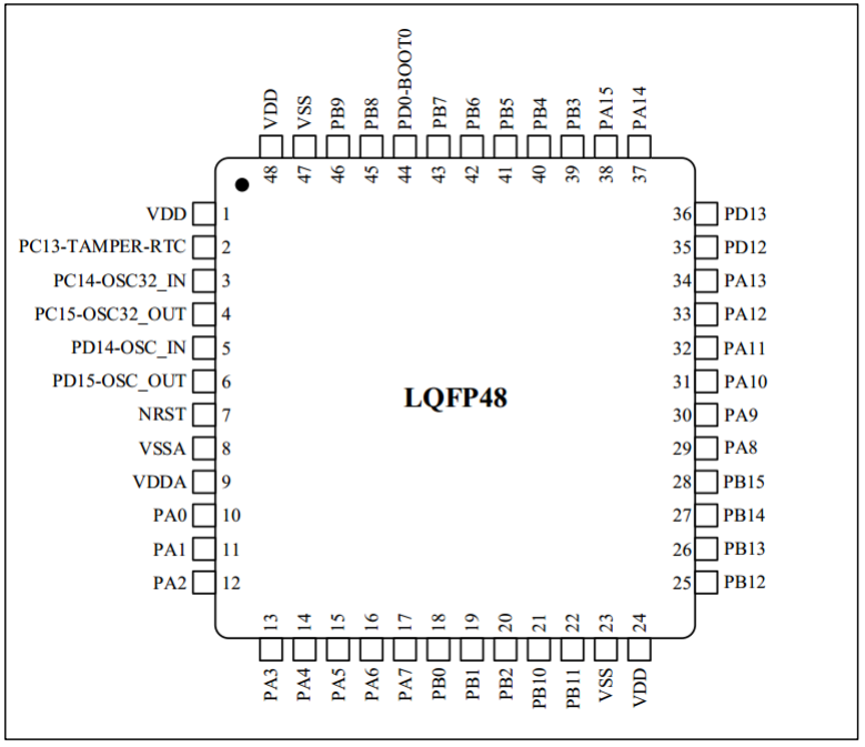
The N32G430C8L7 microcontroller product adopts a high-performance 32-bit ARM Cortex™-M4F core, integrates a floating-point unit (FPU) and digital signal processing (DSP), and supports parallel computing instructions. The highest working frequency is 128MHz, integrates up to 64KB on-chip encrypted storage Flash, supports multi-user partition authority management, and supports 16KB embedded SRAM. It has an internal high-speed AHB bus, two low-speed peripheral clock buses APB and bus matrix, supports 40 reusable I/Os, provides a rich set of high-performance analog interfaces, including a 12-bit 4.7Msps ADC, supports 16 external input channels and 3 internal channels, and provides a variety of digital communication interfaces, including 4 U(S)ARTs, 2 I2Cs, 2 SPI/I2Ss, and 1 CAN 2.0B communication interface. The N32G430C8L7 microcontroller product can stably operate in a temperature range of -40°C to +105°C, with a supply voltage of 2.4V to 3.6V, and provides a variety of power consumption modes. The following figure is the pin distribution diagram of the N32G430C8L7 microcontroller;
3. Sensor introduction
3.1 MPU6050 module
MPU6050 is the world's first integrated 6-axis motion processing component launched by InvenSense. Compared with multi-component solutions, it eliminates the problem of inter-axis difference when combining gyroscopes and accelerometers, and reduces installation space. MPU6050 integrates 3-axis gyroscopes and 3-axis acceleration sensors, and contains a second IIC interface that can be used to connect external magnetic sensors, and uses its own digital motion processor (DMP: Digital Motion Processor) hardware acceleration engine to output complete 9-axis fusion calculation data to the application end through the main IIC interface. With DMP, we can use the motion processing database provided by InvenSense to easily realize attitude solution, reduce the load of processing operations on the operating system, and greatly reduce the difficulty of development.
The features of MPU6050 include
the digital output of 6-axis or 9-axis (external magnetic sensor required) rotation matrix, quaternion, Euler Angle format (Euler Angle forma) fusion calculation data (DMP support required),
131 LSBs/° /sec sensitivity and full-grid sensing range of ± 250, ± 500, ± 1000 and ± 2000°/sec 3-axis angular velocity sensor (gyroscope),
integrated programmable control, 3-axis acceleration sensor with a range of ± 2g, ± 4g, ± 8g and ± 16g,
removal of sensitivity between accelerometer and gyroscope axes, reducing the impact of settings and sensor drift;
built-in digital motion processing (DMP: Digital Motion Processing) engine can reduce MCU Complex fusion calculation data, sensor synchronization, posture sensing, etc.;
built-in operation time deviation and magnetic sensor correction calculation technology, eliminating the need for customers to perform additional calibration;
comes with a digital temperature sensor;
with a digital input synchronization pin (Sync pin) to support video electronic image stabilization technology and GPS;
programmable interrupts (interrupt), support posture recognition, panning, screen zooming, scrolling, fast descent interrupts, high-G interrupts, zero motion sensing, touch sensing, and shake sensing functions;
VDD supply voltage is 2.5V± 5%, 3.0V± 5%, 3.3V± 5%; VLOGIC can be as low as 1.8V± 5%;
gyroscope operating current: 5mA, gyroscope standby current: 5uA; accelerometer operating current: 500uA, accelerometer power saving mode current: 40uA@10Hz;
comes with 1024 bytes FIFO, which helps to reduce system power consumption;
up to 400Khz IIC Communication interface;
Ultra-small package size: 4x4x0.9mm (QFN)
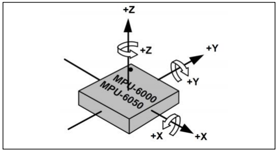
The detection axis and direction of the MPU6050 sensor are shown in Figure 1 below:
1.MPU6050 hardware connection
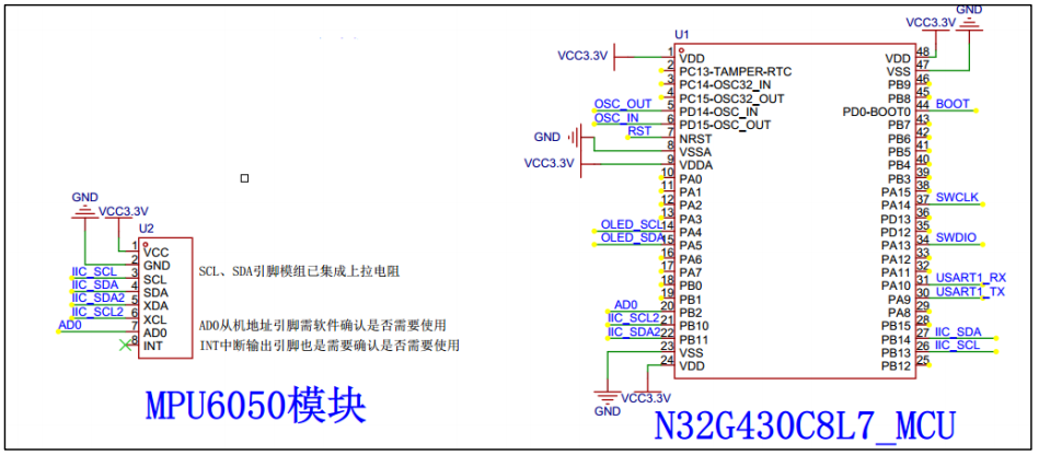
As shown in the figure above, here our MCU controls the MPU6050 through this I2C interface (IIC_SCL/IIC_SDA connects to PB13/PB14 of the MCU), AD0 is the address control pin from the I2C interface (connected to the MCU), and this pin controls the lowest bit of the IIC address. If connected to GND, the IIC address of the MPU6050 is: 0x68, if connected to VDD, it is 0x69. In this project, this pin is directly connected to PB2 of the MCU, and the software is directly pulled down, so the I2C address of the MPU6050 is 0x68.
Note: In order to facilitate the study of the I2C protocol, the driver code of the MPU6050 in this example uses the I2C interface simulated by GPIO.
Note: The address here does not include the lowest bit of data transmission (the lowest bit is used to indicate reading and writing)!
2.MPU6050 initialization configuration process
1. Initialize the IIC interface:
Initialize the SDA and SCL data lines connected to the MPU6050, set AD0 to a low level, and then select the I2C address as 0x68.
2. Reset MPU6050:
This step restores all registers inside the MPU6050 to their default values, which is achieved by writing 1 to bit7 of the power management register 1 (0X6B). After reset, the power management register 1 restores the default value (0X40), and then the register must be set to 0X00 to wake up the MPU6050 and enter normal working state.
3. Set the full scale range of the angular velocity sensor (gyroscope) and the acceleration sensor:
In this step, we set the full scale range (FSR) of the two sensors, respectively, through the gyroscope configuration register (0X1B) and the acceleration sensor configuration register (0X1C). We usually set the full scale range of the gyroscope to ± 2000dps and the full scale range of the accelerometer to ±2g.
4. Set other parameters:
Here, we also need to configure the following parameters: disable interrupt, disable AUX IIC interface, disable FIFO, set gyroscope sampling rate, and set digital low-pass filter (DLPF). In this chapter, we do not use interrupt to read data, so we disable interrupt, and we do not use AUX IIC interface to connect other sensors, so we also disable this interface. They are controlled by interrupt enable register (0X38) and user control register (0X6A) respectively. MPU6050 can use FIFO to store sensor data, but we did not use it in this chapter, so we disable all FIFO channels, which is controlled by FIFO enable register (0X23). The default value is 0 (i.e., FIFO is disabled), so the default value is OK. The gyroscope sampling rate is controlled by sampling rate divider register (0X19), and we usually set this sampling rate to 50. The digital low-pass filter (DLPF) is set through the configuration register (0X1A). Generally, DLPF is set to 1/2 of the bandwidth.
5. Configure the system clock source and enable the angular velocity sensor and accelerometer:
The system clock source is also set through the power management register 1 (0X1B). The lowest three bits of this register are used to set the system clock source selection. The default value is 0 (internal 8MRC oscillation), but we generally set it to 1 and select the x-axis gyro PLL as the clock source to obtain a higher precision clock. At the same time, enable the angular velocity sensor and accelerometer. These two operations are set through the power management register 2 (0X6C). Set the corresponding bit to 0 to enable;
3. MPU6050 Important Register Description
This part can refer to the "MPU-6000 & MPU-6050 Register Table and Description (Chinese Version)" document
4. DMP Usage
From the relevant registers of MPU6050, we can read the raw data of the accelerometer and angular velocity sensor. However, these raw data are not very useful for beginners who want to do quadcopter. What we expect is attitude data, that is, Euler angles: heading angle (yaw), roll angle (roll) and pitch angle (pitch). With these three angles, we can get the current attitude of the quadcopter, which is the result we want. To get Euler angle data, we have to use our raw data to perform attitude fusion solution, which is more complicated and has many knowledge points, and it is not easy for beginners to master. The MPU6050 comes with a digital motion processor, namely DMP, and InvenSense provides an embedded motion driver library for MPU6050. Combined with the DMP of MPU6050, our raw data can be directly converted into quaternion output. After obtaining the quaternion, the Euler angle can be easily calculated to obtain yaw, roll and pitch. The use of built-in DMP greatly simplifies the code design of the quadcopter, and the MCU does not need to perform the attitude solution process, which greatly reduces the burden on the MCU, so that there is more time to handle other events and improve the real-time performance of the system.
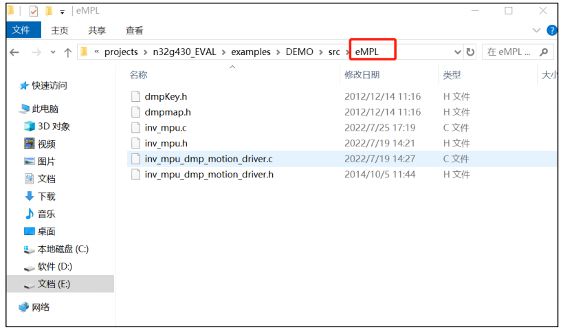
The official DMP driver library is relatively simple to transplant. First, add the two files inv_mpu.c and inv_mpu_dmp_motion_driver.c to the project. Then implement these four functions: i2c_write, i2c_read, delay_ms and get_ms. We will not introduce the details in detail. The transplanted driver code is placed in this example src eMPL folder, a total of 6 files, as shown in the figure below:
We added several functions to inv_mpu.c for our convenience. The focus is on two functions: mpu_dmp_init and mpu_dmp_get_data. Here we briefly introduce these two functions. u8 mpu_dmp_init(void); //mpu initialization, note: this function is time-consuming, about 3-4s, no actual measurement. u8 mpu_dmp_get_data(float *pitch, float *roll, float *yaw); Get the attitude data pitch, roll, yaw. The specific implementation of this function can refer to the source code comments.
3.2 OLED module
1. OLED module hardware connection
As shown in Figure 7 above, here our MCU controls the display of OLED through the IIC interface (OLED_SCL/OLED_SDA connects to MCU's PA4/PA5). In order to quickly get familiar with the N32G430 chip, the I2C driver of OLED, this case uses hardware I2C1. As shown in Figure 6 above, the address selection resistor on the back of the OLED module jumps to the left, so its slave address is 0x78. Note: The address here does not contain the lowest bit of data transmission (the lowest bit is used to indicate read and write)!


2. OLED initialization configuration process
1. Initialize the IIC interface
to initialize the SDA and SCL data lines connected to the OLED.
2. Turn off the OLED display
and set the OLED register parameters. After turning off the OLED display, configure the register parameters, such as setting the clock division factor, oscillation frequency, setting the display contrast, scanning direction, pre-charge cycle, brightness and other parameters. For the specific meaning, please refer to the OLED register description document or other online materials. I will not elaborate on it here.
3. Turn on the OLED display
4.3 Important OLED register description
This part can refer to the following website: https://wenku.baidu.com/view/fb23e3a4bfeb19e8b8f67c1cfad6195f302be849.html;
4. Spatial coordinate conversion algorithm
4.1 Three-dimensional coordinate system conversion
The three-dimensional coordinate transformation in space is generally realized by the following three methods:
rotation matrix and rotation vector;
Euler angle;
quaternion.
Here we introduce the method of realizing three-dimensional space coordinate transformation by rotation matrix (rotation vector) and Euler angle and the relationship between the two. Here we take the common camera coordinate system conversion to the world coordinate system, that is, the more common body to world coordinate system conversion as an example. Then the Euler angle of rotation is converted from the world coordinate system to the camera coordinate system, first rotating along the z-axis, then the y-axis, and then the x-axis, and finally obtaining the camera coordinate system. The angles obtained are yaw, pitch, and roll, respectively. Then the rotation matrix from the camera coordinate system to the world coordinate system is defined as follows.


For the above matrix algorithm, you can refer to the relevant information of Baidu. Since the x and y axes of the cube are inconsistent with the x and y axes of the sensor in the code, the code swaps Rx and Ry to ensure that the direction of the OLED cube is consistent with the direction of the sensor, so as to adjust the posture to be consistent. Since the coordinate points of the three-dimensional are to be displayed on a two-dimensional plane, if point P (x0, y0, z0), it is necessary to project point P on the XOY plane, that is, z0 = 0, that is, the coordinates of P1 on the plane are (x0, y0). Based on the above analysis, if you want to display the cube on the plane, you only need to project the eight coordinate points of the converted cube onto the XOY plane, and then connect the above points in sequence to get a cube. In order to highlight the change of the cube's posture, this example program connects an additional x-shaped surface.
5. Software Design Process
5.1 Software Flowchart
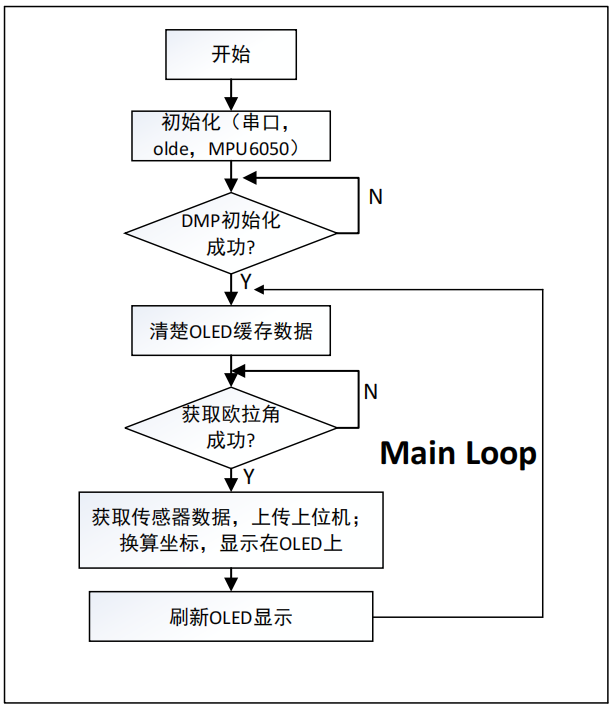
The software initialization process is divided into the following steps:
Initialization:
Some of them include serial port, hardware IIC, GPIO simulated I2C, OLED, MPU6050 and DMP initialization; -log_init(): 500000Bd, no parity, 8-bit data, 1 stop bit. This interface can send and receive data and log printing; -i2c_master_init (): In order to improve the refresh speed of OLED, the IIC speed is set to 400k, without ACK response; -oled_init(): mainly the register parameter configuration of OLED, for details, please refer to SSD1306 controller; -MPU_Init(): configure the register parameter configuration of MPU6050, including address, sampling rate, acceleration/gyroscope full scale range and other parameters. -mpu_dmp_init(): DMP initialization, here wait for DMP initialization to complete.
VI. Physical Demonstration
6.1
After power-on and power-on reset, the module posture is horizontal and static.
The host computer displays the screen when static.

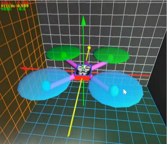
6.2 The module is tilted 45 degrees to the right
. The OLED display is tilted 45 degrees to the right.

The upper computer display is tilted 45 degrees to the right.

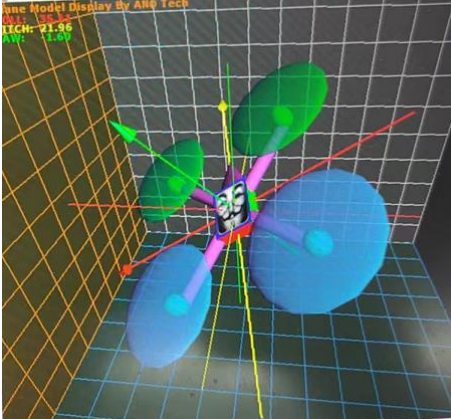
6.3 The module is tilted
35 degrees to the left and 21 degrees downward. The OLED display is tilted 35 degrees to the left and 21 degrees downward.

The upper computer display is tilted 35 degrees to the left and 21 degrees downward.
Notes
After reset, it usually takes 3-4 seconds for the OLED to display normally. This is mainly because there is a self-calibration process of MPU6050 during the DMP initialization process. Therefore, for the user's experience, you can consider displaying "calibrating" on the OLED as a prompt;
after reset, the module must be placed flat and the sensor calibration is completed before moving the module;
users can modify the Set_Slaver_Address() function to configure PB2 to pull up and down to modify the MPU6050 address. In the code, PB2 is pulled down, so the address of MPU6050 is 0x68.
After a period of time, the Euler angle Yaw has obvious drift. This is because the magnetic sensor is not added for algorithm fusion, which is a normal phenomenon. Those who are interested can study how to solve the drift problem.


 京公网安备 11010802033920号

 Z0803606RME


