## Question requirements
"Graduation project of Internet of Things controller based on LORA network"
## Question analysis
This design is based on LORA network for data transmission, and uses a single-chip microcomputer as the controller to collect signals and control the equipment.
##
Tips: Overall design scheme block diagram
column:
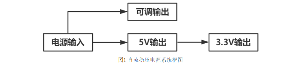
## Schematic design description
The power circuit consists of the power indicator circuit, It consists of lightning protection circuit, short circuit protection circuit, 5V voltage stabilizing circuit and 3.3V voltage stabilizing circuit. Please refer to the schematic diagram for the specific circuit. The minimum system circuit consists of a microcontroller, a reset circuit and a crystal oscillator circuit. Please refer to the schematic diagram for the specific circuit. The analog input circuit consists of a resistor voltage divider circuit, an ESD circuit, and a filter circuit. Please refer to the schematic diagram for the specific circuit. The analog output circuit consists of an optocoupler circuit, PAC chip, PMOS circuit, ESD circuit and filter circuit. Please refer to the schematic diagram for the specific circuit. The digital output circuit (relay) consists of a relay drive circuit and a relay. Please refer to the schematic diagram for the specific circuit. The digital output circuit (transistor) consists of a level conversion circuit and NMOS. Please refer to the schematic diagram for the specific circuit. The RS485 communication circuit consists of the MAX485 chip, transceiver conversion circuit, ESD circuit, and filter circuit. Please refer to the schematic diagram for the specific circuit. The LORA communication circuit consists of a jumper cap and a LOAR module. Please refer to the schematic diagram for the specific circuit.
## PCB design instructions
In terms of PCB layout, attention should be paid to the location of the terminal blocks to facilitate installation. The line width is set according to the current size, usually 1mm flows through 1A current. In order to improve the accuracy of analog quantity collection, high-precision resistors can be selected.
## Software description
In order to prevent the design from being plagiarized, the software code is not provided.
**Code block:**
```
#include
void main()
{
printf(""/n);
}
```
##
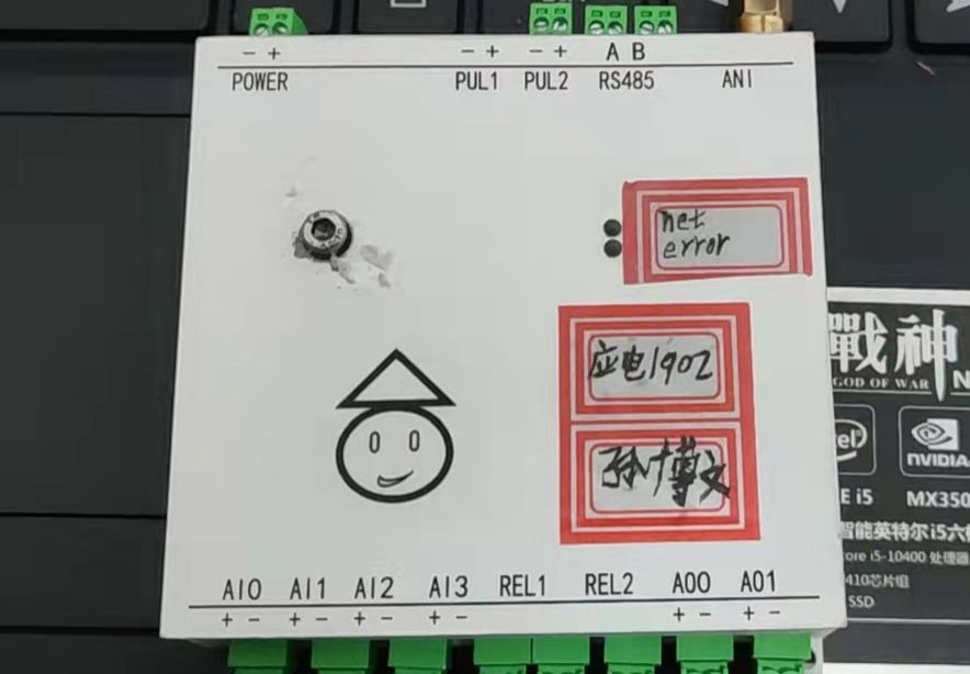
Tips for physical display instructions: physical pictures of the work, and descriptions can be added to the pictures.
## Note:
This design is powered by a 6V DC power supply and is available on Taobao.
## Demo video
tips: Just upload attachments to the demo video. Attachments can only be long-distance uploaded files of up to 50M. Files larger than 50M can be placed on other network disks or video websites. Just put the address link here.
## Tips for uploading other attachments
: Works participating in the event must upload project-related program attachments to the open source platform or personal code storage cloud. Attachments can be uploaded up to 50M (please do not upload them in the Lichuang workspace, there are restrictions)


 京公网安备 11010802033920号

 240-0324-9SCC4K1-18M


