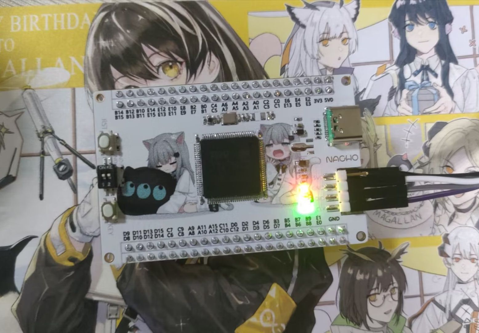
The development board is compatible with the STM32F103VxTx series of chips. The author uses the STM32F103VET6 chip. You can also replace it with other chips of the same series.
There are several common problems with the board as follows:
1. The resistor and capacitor are all in 0402 packaging, which is difficult for novices to solder, and the Type -C is somewhat difficult. Here I will give you a method to make welding easier.
(1). Buy a fairy’s LED disassembly heating plate. Choose the power according to your own needs. It is recommended to choose a larger heating plate.
(2). Use a bladed soldering iron to pre-solder the chip on the board. If there is tin, apply some flux to pick out the tin, or use a soldering tape to suck it out.
(3). Use solder paste to evenly apply on the resistor and capacitor pads. Remember to tin the Type-C interface and pads in advance (not solder paste), and apply an appropriate amount of flux.
(4). After arranging all the components, place them away from the heating center and let the board heat up slowly. If you encounter "tombstones" during this period, use tweezers to straighten the resistors and capacitors.
(5). Solder all the pin headers, and remember to tin the Type-C fixed pins. At this point, a Nekoha Shizuku-themed development board is soldered.
2. If you are unable to program, please check whether the boot DIP switch is set to "GND". If you still cannot program, check whether the chip is soldered.
3. For the linear voltage regulator "CAJ1117", if you don't understand it, please be sure to buy the same chip. It is not recommended to use other chips. If you use other SOT-89 packaged voltage regulator chips, please be sure to check whether its pin sequence is wrong. The use of HT7833 is prohibited. The author burned a lot of chips just because of the convenience of using HT7833 (because the input and output pins of the two chips are opposite, which will cause the wrong output of 4.5V high voltage and cause the chip to burn).

