The first prize of the 13th Electronic Design Competition of Wuhan University of Technology
Team name: Yi Jiajing
Team members: Zhang Jiaming, Li Gaojing, Liu Yi
Instructor: Zhang Jialiang
Competition topic:
DC motor control system
I. Task
Make a current feedback DC motor control system and complete the corresponding test device. (Draw a
system block diagram)
II. Requirements
(1) The system uses +12V power supply, and makes a boost circuit to provide +15V power supply for the motor. The
boost circuit requires the maximum output voltage error of ±3% under resistive load conditions, and the maximum output current ≥3A.
Under full load, the efficiency is ≥90%, and the ripple is less than 200mVpp; under inductive load (DC motor no-load
movement ), the maximum output voltage error is ±6%, and the ripple is less than 500mVpp. (15 points)
Improvement part: If all the above indicators are met, at least 3 indicators can be significantly
optimized (accuracy, load capacity, etc. are doubled, ripple is reduced by half, and efficiency is increased by 5%), you can get extra
points. (5 points)
(2) Make an auxiliary power supply that meets the normal working requirements of the system to
power The static current of the system is required to be less than 5mA. (That is, the system should try to reduce
power consumption when there is no test task. When the system is tested, an ammeter will be connected in series at the input end to monitor the system working current). (5 points)
(3) Make a motor drive circuit that can realize motor polarity switching (forward and reverse switching), can output
instantaneous maximum current ≥10A, rated current ≥5A, and working voltage 12-24V. (10 points)
(4) Make a motor current detection circuit. The system is required to be powered by a single power supply, with a current monitoring accuracy better than
1%, and when the current changes dynamically, the monitoring bandwidth is greater than 1KHz. The detection results are transmitted
to the computer display through a wireless transmission module. (20 points)
(5) Use the encoder speed feedback method to control the motor movement, and vertically pull a 1KG object to achieve
the following movement process: static-acceleration-uniform speed (the speed of uniform speed movement
is determined according to actual conditions). During the uniform upward movement, by increasing the weight of the object, when the motor current
reaches , the buzzer is controlled to realize overload
alarm. During the uniform downward movement, by increasing the weight of the object, when the motor current reaches
50% of the current when the 1KG object is pulled vertically to fall, the buzzer is controlled to realize stall alarm. (15 points)
Note: The total weight of the object does not exceed 2kg, and the added object has no initial velocity.
(6) Use the current feedback method to control the motor movement, and pull the 1KG object vertically to realize the following movement
process: static-acceleration-uniform speed. When static, start by pressing the button to realize the static-acceleration process. The acceleration
movement distance is 0.3 meters (strictly guaranteed), the final speed is 0.3 meters/second, the uniform movement distance is 1
meter, and it decelerates and stops immediately after exceeding 1 meter (not required). The ascending and descending are tested independently. (15 points)
Note: When actually scoring, the encoder in (5) needs to be in a non-working state; if the motor motion is controlled by using
encoder feedback to meet the requirements of this question, no points will be awarded.
(7) The motor needs to have a speed detection function (absolute value encoder, etc.), and a self-made speed and
distance measurement and display system, and the instantaneous measurement results are transmitted to the PC through a wireless module for verification. The circuit system of this part
is required to be independently powered and work independently, and has no electrical
connection with the above-mentioned control system, drive system, etc. (that is, it must not share power or ground with the motion control system). The evaluation process will be compared with standard instruments and
equipment . (15 points)
III. Supplementary matters
(1) This system involves system
design . Each sub-function is evaluated and scored independently. Students can make their own choices based on their own knowledge reserves, and
scores will be given priority!
(2) In the system, except for the controller core board (microcontroller, FPGA, DSP, etc.) and the wireless module, which
can use finished modules, other components such as auxiliary power supply, motor drive module, signal detection module, etc.
are required to be self-made (draw circuit boards).
(3) It is recommended to use WIFI, BLE and other serial port modules as wireless modules.
This project only shows part of the circuit design.
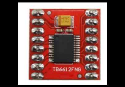
This project uses the ACS712 current detection module and the TB6612 motor drive module. The voltage information read by the AD is collected by the STM32 main control board, and the corresponding parameters are output to the motor drive module to control the motor speed, etc.


 京公网安备 11010802033920号

 K4S561632A-TC/L1L


