The STM32F103RBT6 minimum system board has been verified and all functions are working properly.


c646298e6bde0a1404a20ca54d9c8c61.mp4
PDF_STM32F103RBT6 Minimum System Board.zip
Altium_STM32F103RBT6 Minimum System Board.zip
PADS_STM32F103RBT6 Minimum System Board.zip
BOM_STM32F103RBT6 Minimum System Board.xlsx
96238
ESP32 remote control car
A remote-controlled car implemented using the HeZoo ESP32C3 development board.

The mainboard code for the remote control car based on the Heze ESP32C3 development board is available at: https://gitee.com/fanjunwei/esp32c3_car_recive. The iOS app code for the remote control is also available at: https://gitee.com/fanjunwei/esp32c3_car_send_ios. The iOS remote control code is also available at: https://gitee.com/fanjunwei/esp32c3_car_send
. Note that the development board image in the schematic diagram is mirrored.
PDF_ESP32 Remote Control Car.zip
Altium_ESP32 Remote Control Car.zip
PADS_ESP32 Remote Control Car.zip
BOM_ESP32 Remote Control Car.xlsx
96239
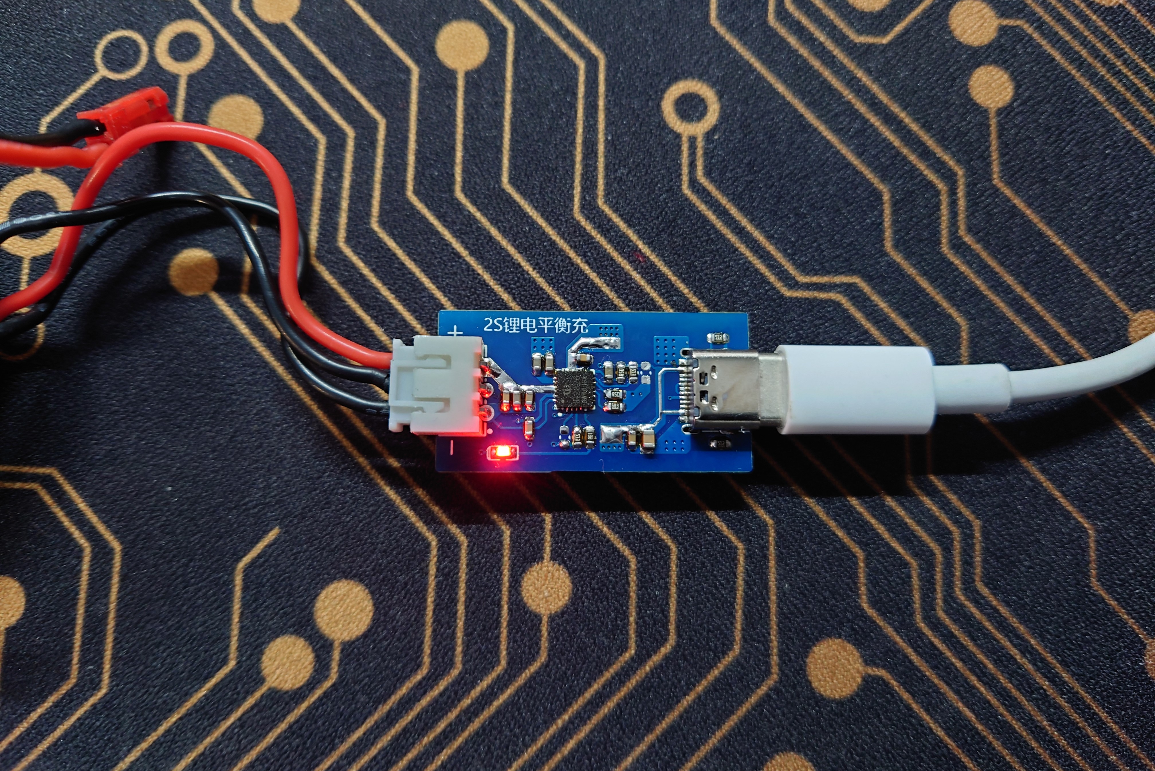
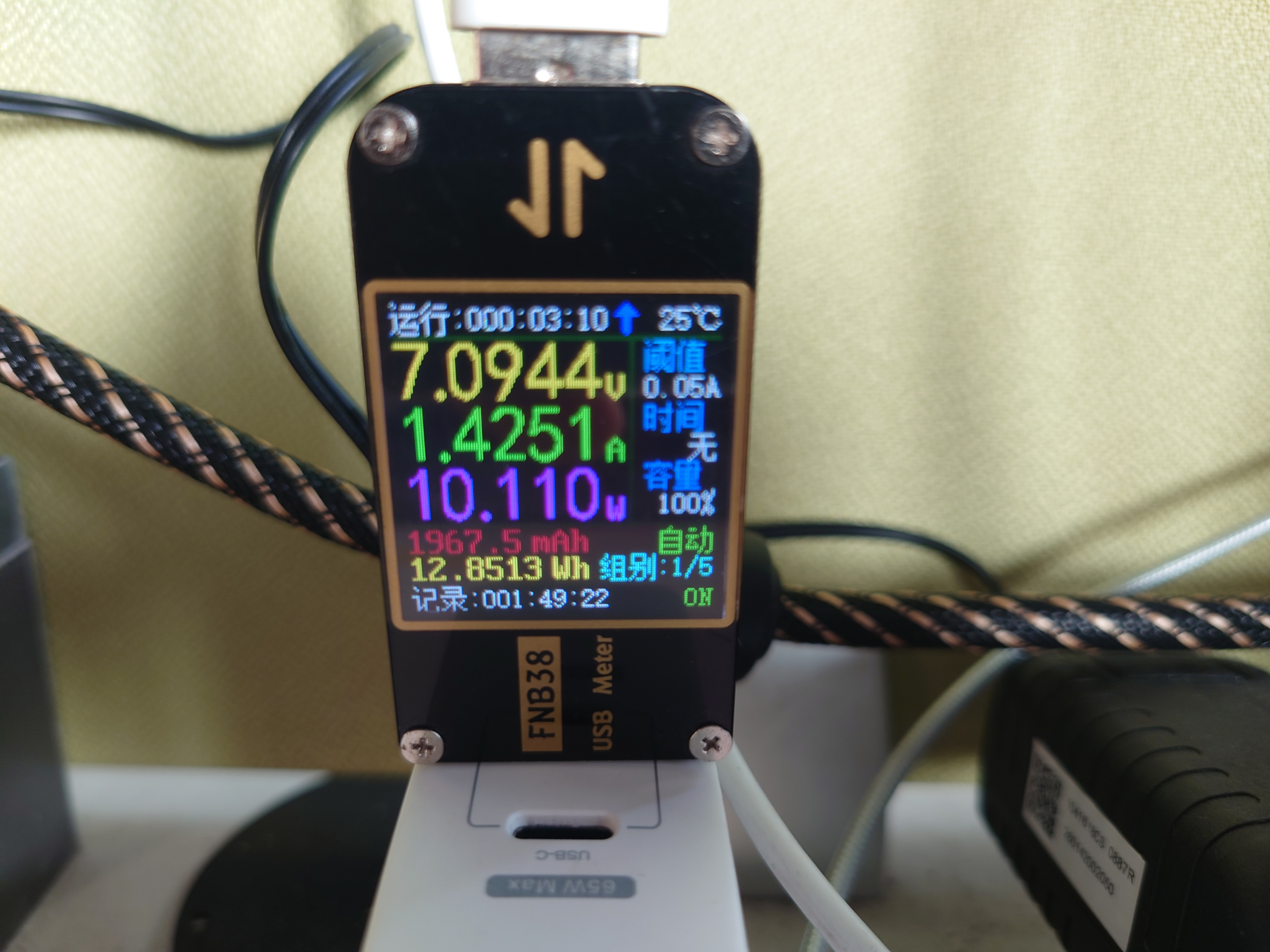
IP2326 verification board with 2 series lithium battery balance chargers
The IP2326 is a boost charging IC for 2/3 series-connected lithium batteries that supports 15W fast charging.
IP2326 Features:
15W synchronous switching boost charging
, 94% boost charging efficiency, built-in integrated charging equalization circuit
with power MOS , supports fast charging input request based on battery voltage to improve charging efficiency, constant voltage charging voltage, adjustable external resistor, pin-configurable 2- or 3-series lithium battery charging, adjustable external resistor for automatic fast charging input request based on battery voltage, automatically adjusts input current to adapt to adapter load, supports charging NTC temperature protection , input overvoltage and undervoltage protection with adjustable external resistor, charging timeout protection with adjustable external resistor, supports LED charging status indication , 500KHz switching frequency, supports 2.2uH inductor output, overcurrent, overvoltage, and short circuit protection, IC overtemperature protection, input withstand voltage 25V ESD 4KV 2S, normal lithium battery charging test, normal fast charging trigger, stable operation.
IP2326.pdf
PDF_IP2326 Verification Board 2-Series Lithium Battery Balance Charger.zip
Altium_IP2326 verification board 2-cell lithium battery balance charger.zip
PADS_IP2326 verification board 2-cell lithium battery balance charger.zip
BOM_IP2326 Verification Board 2 Series Lithium Battery Balance Charger.xlsx
96240
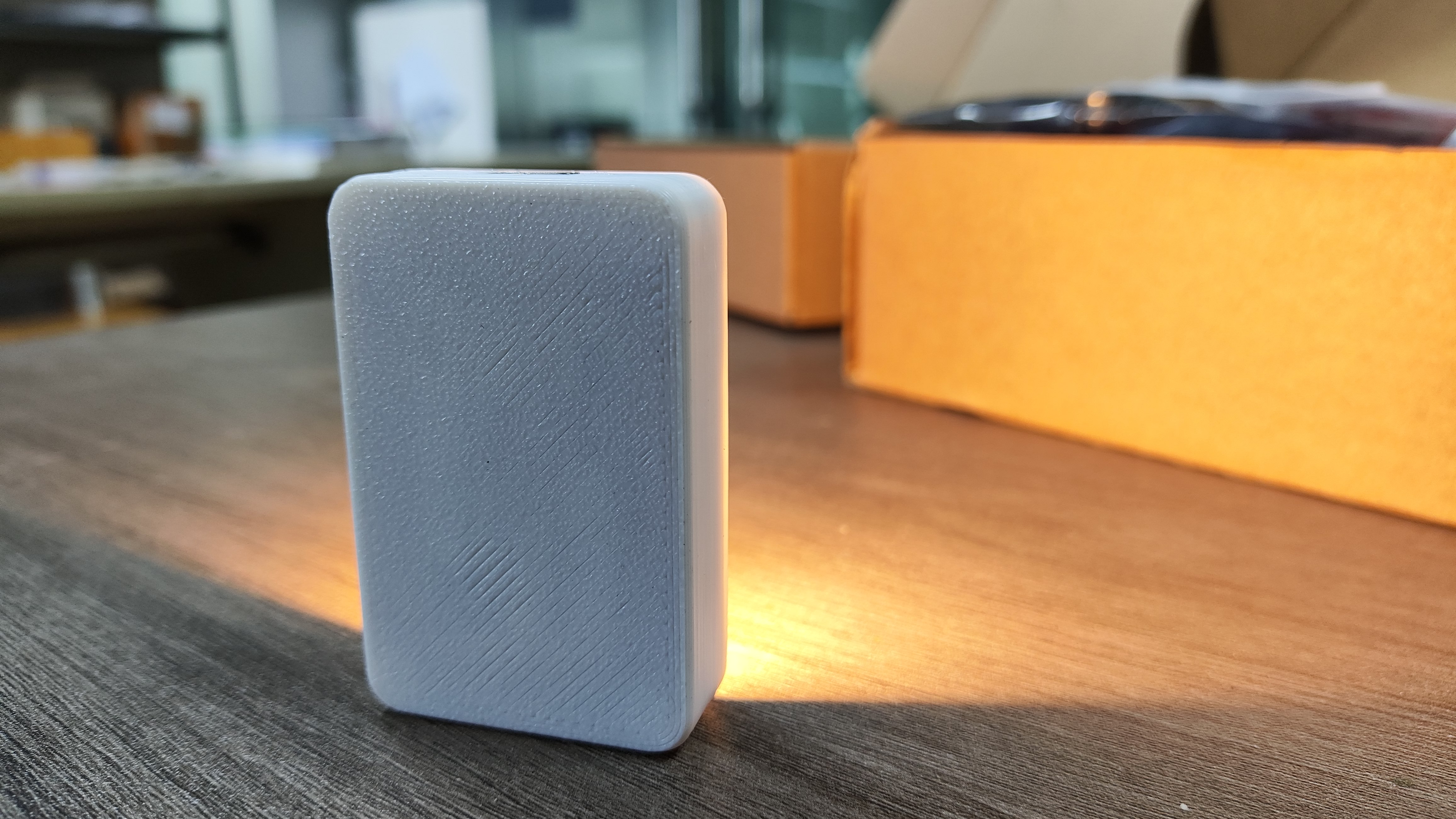
cozy night light
This ultra-refined night light features the RH6618A touch dimming chip, a TP4057 charging module, three dimming modes, a light reflector, a 450mAh lithium battery, and an ultra-long battery life of 8+ hours (brightest mode)!
Exploded View ,

Physical Schematic,


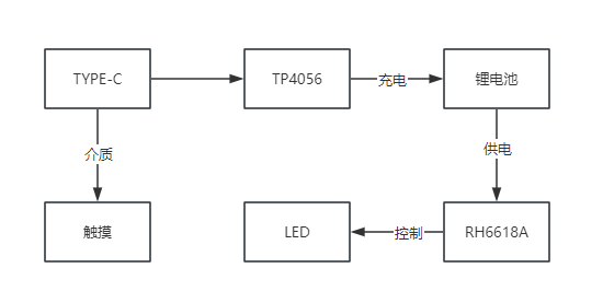
Project Programming Diagram,
Schematic Design Instructions:
1. H1 is the lithium battery soldering interface (no components need to be placed on the solder pad).
2. R4 is the charging current setting resistor, maximum 500mA.

PCB Design Instructions:
1. The TYPE-C housing is the touch medium and does not have a common ground
. 2. The size of the touch sensor pad needs to be designed according to parameters such as panel medium and panel thickness. 2.1 Sensing Line: On the PCB, the touch sensor pad should be as short as possible from the IC's touch input pin (sensing line). The sensing line should be at least 1mm away from copper plating or other traces, and the wire diameter should be 0.15mm~0.2mm. 2.2 Copper Plating: If there are radio signals, high-voltage devices, or magnetic fields near the touch panel, please use 20% mesh grounded copper foil for copper plating. To balance penetration and anti-interference capabilities, avoid copper plating under the touch pad as much as possible. The copper plating should be at least 2mm away from the touch sensor pad and at least 1mm away from the sensing line. 2.3 The coating on the media panel or surface covering the touchpad must not contain conductive materials or metallic components, and the entire metal casing must not be used as the sensing electrode.
Notes:
1. Acrylic thickness is 1.5mm
. 2. Battery thickness is 30 x 40 x 4 mm.
3. The reflector needs to be painted with silver spray paint to increase its reflectivity; gold is also acceptable.
4. The video shows the casing printed by my own 3D printer, made of PLA.
5. The colored version has been verified; the casing is not perfect and will be updated later.
Warm Night Light.mp4
Warm Night Light.rar
PDF_Cozy Night Light.zip
Altium_cozy night light.zip
PADS_Warm Night Light.zip
BOM_Cozy Night Light.xlsx
96244
AP5056 charging module
AP5056 1S 3.7V lithium battery charging module; 5V 1A; adjustable charging current;
Version Description
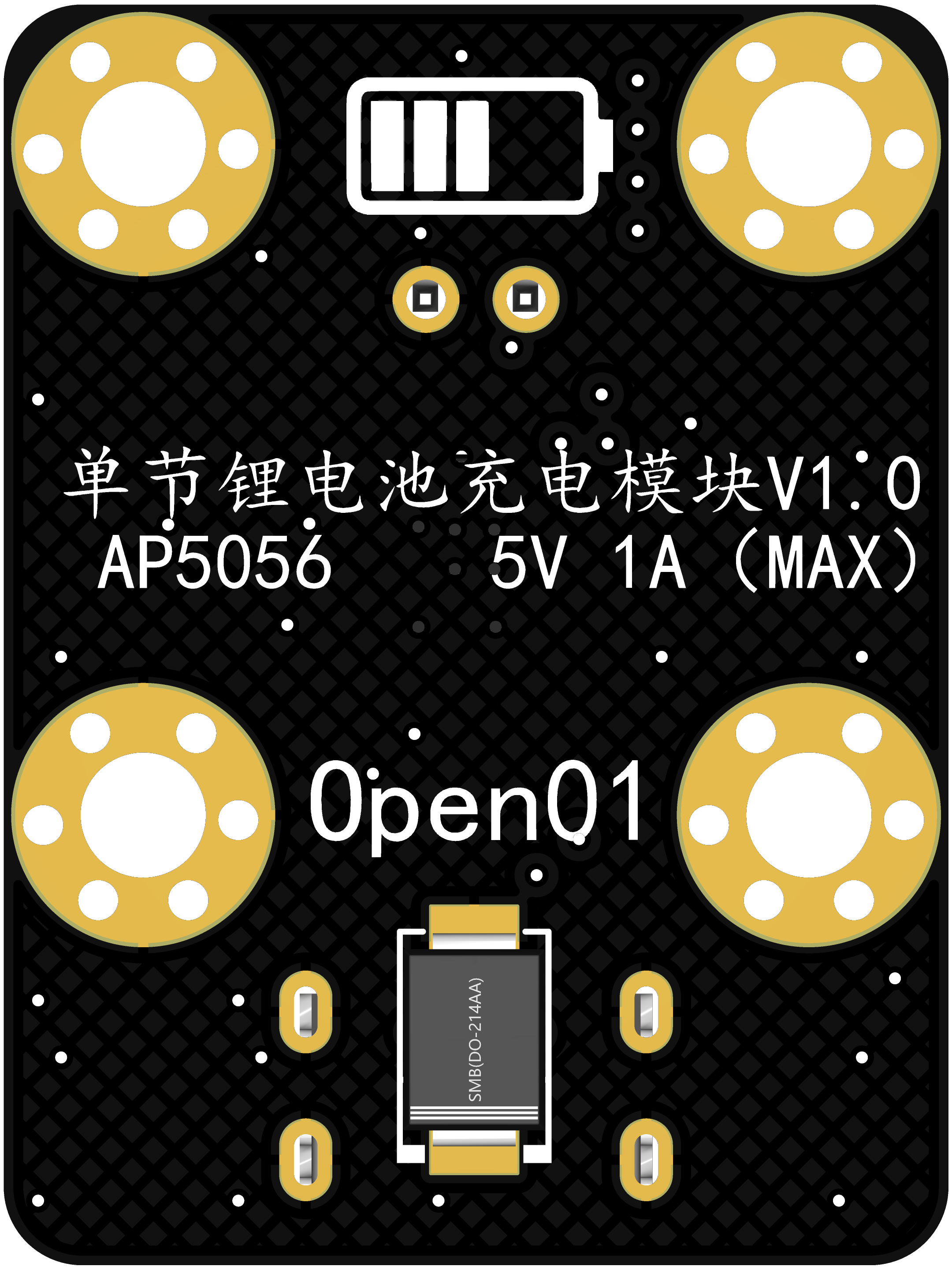
Version Name: Charging Module V1.0, V1.1, V1.2
Release Date: 2023/11/15
Version Name: AP5056 Charging Module V1.3
Update Date: 2024/1/26
Update Content:
Optimized version naming
Added version - AP5056 Charging Module V1.3
I. Project Introduction
Project Introduction Video
Verification Status: Pending Verification
This charging module is used for charging a 3.7V single-cell lithium battery. The charging current is adjustable, with a maximum of 1A.
There are 4 versions:
V1.0 The charging current is determined by the resistance value of the soldered PROG resistor.
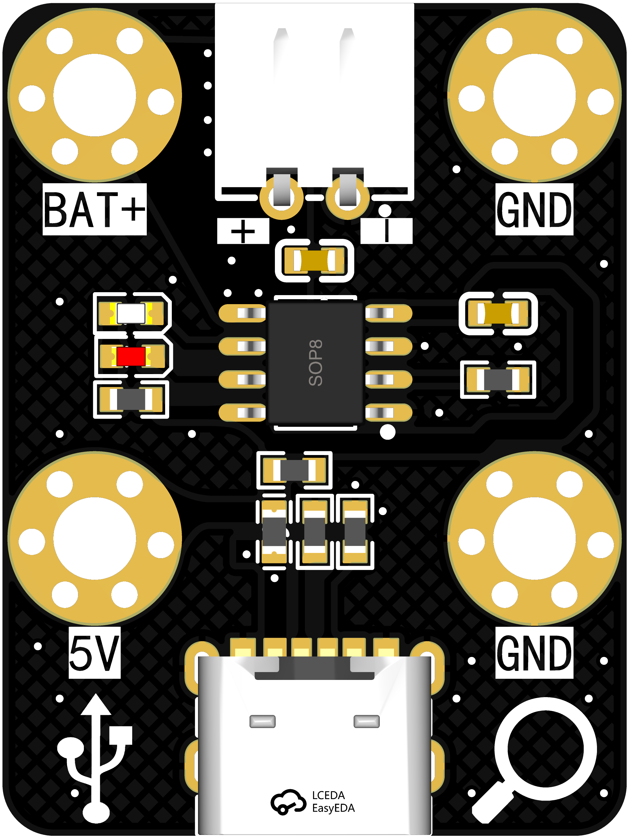
V1.1 The charging current can be set via jumpers.
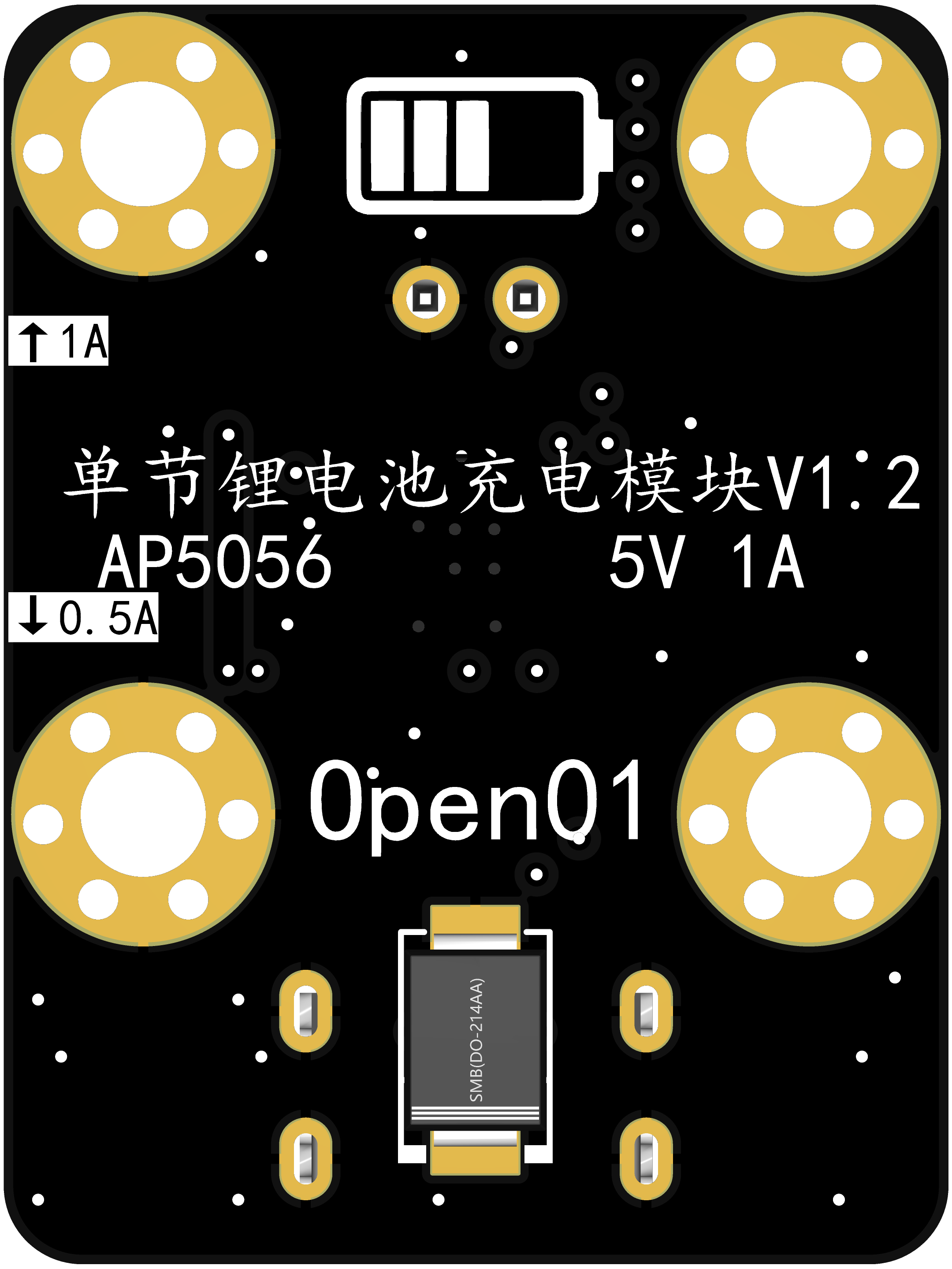
V1.2 The charging current can be set via DIP switches.
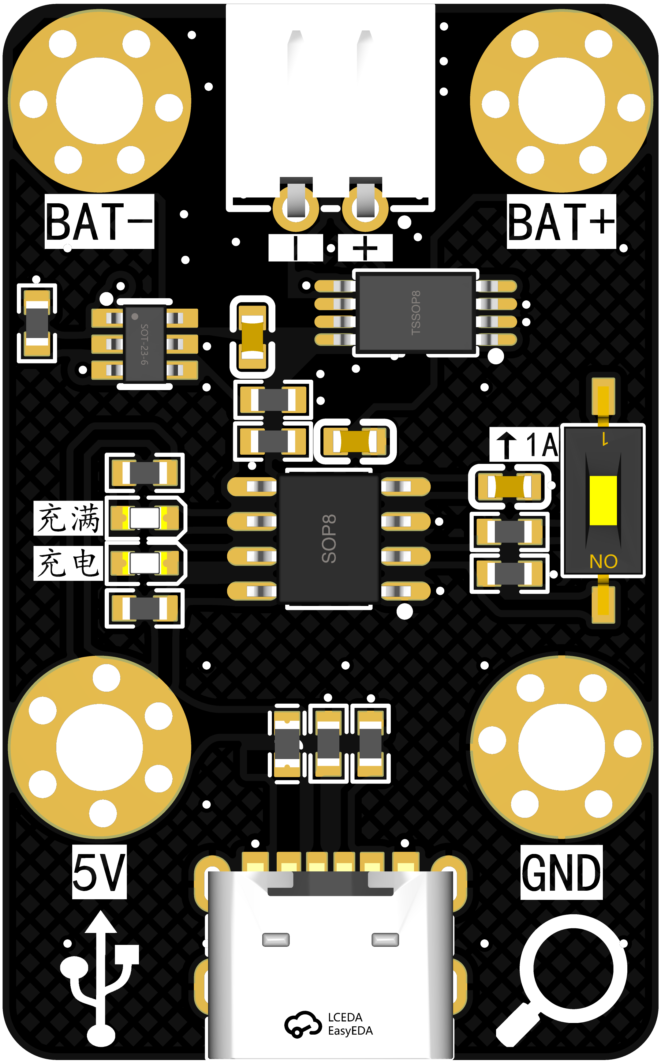
V1.3 adds a charge and discharge protection module to the V1.2 version.
II. Effect Diagrams


III. Functional Modules
1. USB Module
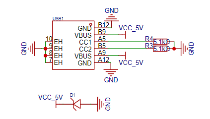
Charging uses a common 6P USB interface, a standard design, which requires no further explanation. D1 is an anti-static diode.
2. The charging module
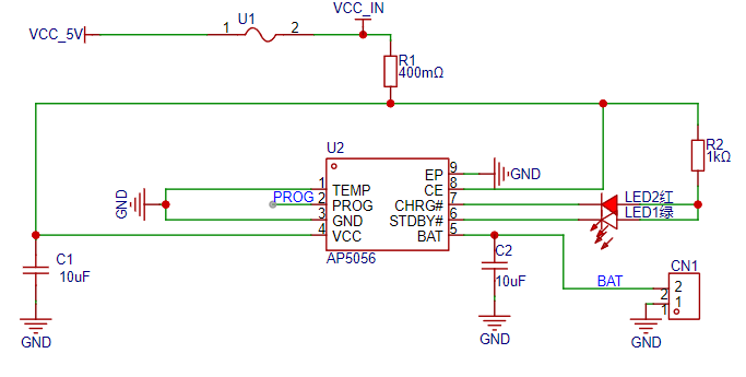
uses the AP5056 charging chip, which is also used on the 01-RTC main control board


, reflecting a cost-saving and efficiency-enhancing approach. This chip is compatible with the TP4056. U1 is a resettable fuse with a rated current of 1A, a trip current of 2A, and a maximum voltage of 6V. Both diagrams show the charging current control. The first diagram is for version V1.1, where current control is achieved through jumper pins. The second diagram is for version V1.2, where current control is achieved through a single DIP switch.
3. The protection module
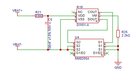
uses the common DW01 and 8205 chips for charge and discharge protection. The schematic is copied; I will study it further later and refine this part.
4.
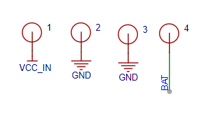

The four screw holes, besides their mounting function, can also be used as power input and output, essentially providing an additional interface for charging to adapt to different scenarios.
IV. Notes on
update time: 11th-15th and 26th-end of each month.
Data acquisition:
UP: open01_T_Jupiter; duduvue;
QQ group: 826793815
moduleShell.stl
PDF_AP5056 charging module.zip
Altium_AP5056 charging module.zip
PADS_AP5056 charging module.zip
BOM_AP5056 charging module.xlsx
96245
electronic


 京公网安备 11010802033920号

 209-521-59-38


