1. Project Title:
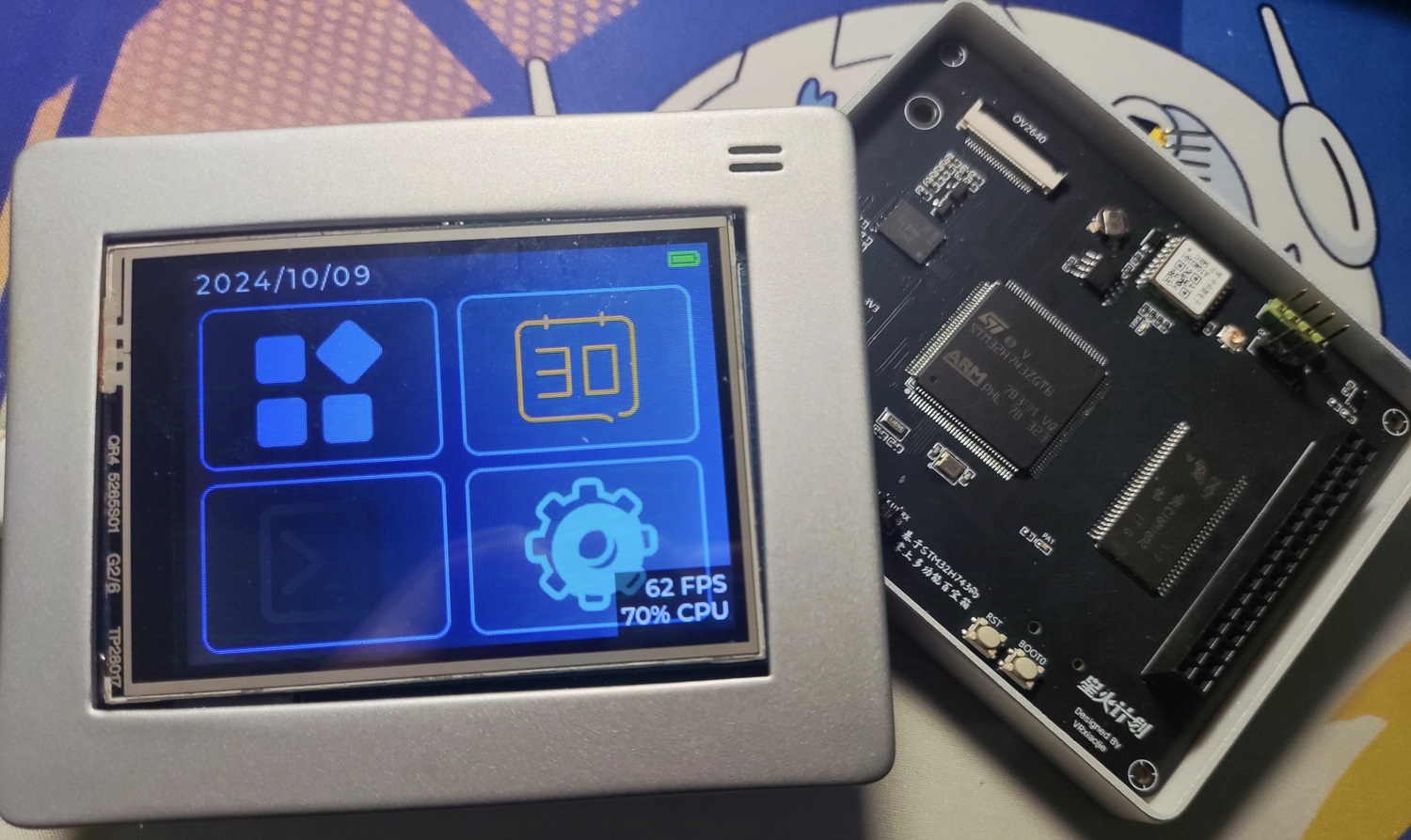
A Handheld Multifunctional Toolbox Based on STM32H743
2. Project Introduction:
I recently attended an STM32 offline seminar and experienced the charm of STM32 in AI applications and GUI acceleration. The STM32H743 is a new high-performance MCU in the STM32 series. Currently, there are very few projects about the H7 series on open-source platforms, and most are development boards. To fully utilize the performance of the H743, this project plans to develop a human-computer interaction interface based on LVGL. The accompanying 2.8-inch touchscreen can eliminate the hassle of button operation and improve the user experience. At the same time, the H743 has many GPIO interfaces, allowing for the connection of many peripherals. This project will use the OV2640 camera, ATGM336H positioning module, SHT40 temperature and humidity sensor, BH1750 ambient light sensor, etc., to implement the corresponding functions for each sensor.
Because this project has many peripherals, is based on a touchscreen for extensive development, and is only palm-sized (slightly larger than a 2.8-inch screen), it is named "Handheld Multifunctional Toolbox." Users can continue to modify and add new functions based on the open-source software code of this project.
3. Hardware Module Introduction
3.1 STM32H743ZGT6 Main Control Chip The
STM32H743ZGT6 is a high-performance MCU in the STM32H7 series, using an ARM Cortex-M7 core with a main frequency of up to 480 MHz, and built-in 2MB FLASH and 1MB RAM. This gives it excellent performance when handling complex tasks, making it particularly suitable for applications requiring fast response. Its rich peripheral interfaces make peripheral connection and control more flexible.
In addition, the design supports DFU download, and programs can be downloaded directly to a computer via USB using STM32CubeProgrammer.
3.2 Expanded SDRAM
This project uses 256Mbit MT48LC16M16A SDRAM (equivalent to 32MB), which is mainly used to store large temporary data and dynamic arrays during runtime. Due to the limited internal RAM capacity of the STM32H743, the addition of external SDRAM significantly expands the system's available memory. When displaying high-resolution graphical interfaces or processing camera images, SDRAM provides ample cache space, laying the hardware foundation for future development of more complex functions.
3.3
The project includes a 256Mbit MT25QL256ABA1EW9-0SIT QSPI FLASH for storing system files and user data. The QSPI interface offers fast read and write speeds, meeting the demands of loading large resources. A reserved MT29F2G01ABAGDWB is used as a backup FLASH for future expansion.
3.4 The external EEPROM
JSM24C02 is a 2Kbit EEPROM used as the storage unit for setting parameters in this project. It primarily stores user preferences, system configurations, and important operating parameters. Compared to FLASH, EEPROM has a longer read/write lifespan and supports multiple write operations for small amounts of data, making it ideal for scenarios with frequent updates but small data volumes. In the event of a power outage, the EEPROM ensures the persistent storage of configuration data, thus preventing data loss due to power failure or restart.
3.5 ATGM336H Positioning Module
The ATGM336H is a high-precision GPS positioning module that can quickly acquire the current location and provide accurate geographic coordinates. In this project, the positioning module is mainly used to implement path tracking, motion trajectory recording, and other functions. Combined with the touchscreen interface, users can view real-time location information. The ATGM336H supports GPS and BeiDou satellite positioning and can obtain stable positioning signals even in complex environments.
3.6 OV2640 Camera Module The
OV2640 is an image sensor with 2 megapixels, supporting photo and video functions at various resolutions. In this project, the OV2640 camera will be used to capture images and combined with the AI library officially released by STM32 to develop artificial intelligence applications such as gesture recognition.
3.7 SHT40 Temperature and Humidity Sensor The
SHT40 is a high-precision temperature and humidity sensor with good stability and fast response capabilities, capable of accurately detecting changes in environmental temperature and humidity. In this project, the SHT40 is primarily used to monitor the environmental conditions around the equipment, ensuring users can access real-time temperature and humidity data, and developing related environmental monitoring functions based on this.
3.8 BH1750 Ambient Light Sensor:
The BH1750 is a digital ambient light sensor used to detect the intensity of light in the surrounding environment. In this project, the BH1750 is mainly used to automatically adjust the brightness of the touchscreen according to changes in ambient light, thereby improving the visual experience. Especially under different lighting conditions, automatic adjustment of screen brightness can effectively reduce eye fatigue.
3.9 2.8-inch Touchscreen:
The touchscreen used is the one shown below, with the driver IC ILI9341, a resistive touchscreen.
http://e.tb.cn/h.gyKlKdaJeWtXDig?tk=mSZ33MEX7nv
If a capacitive touchscreen is used, the display driver source code needs to be modified.
4. Project Schedule
and
Details
2024
-
9.6
Project Concept Creation
9.9
Schematic Diagram Completed
9.11
PCB Design Completed
9.18
Software and UI Development Begins
9.20
Location Module Related Functions Completed
9.23
Main Interface Based on LVGL Completed
9.25
DMA and Buffering Added for Global 60Hz Smooth Refresh
9.26
Shell Design Completed
9.30
SDRAM Driver Development Completed
10.1
QSPI Flash Driver Development Completed
10.6
FatFS Porting Completed
10.9
LVGL File Browser Beta Development Completed
10.10
Project V1.0 Released
10.17
Source Code Open-Sourced on GitHub
5. Software Section
Currently, this project still has features under development. The .hex files in the attachment may not be the latest. We strongly recommend that you clone the code to your local machine through the GitHub repository at the end of this document, and then compile and download it in Keil!
5.1 LVGL Performance Report
Thanks to the H7 series' built-in cache and large RAM, the size of the buffer array and the ability to enable buffering can be increased without restraint. Below is the LVGL performance test table:
| Combination | Frame Rate | CPU |
| :---: | :---: | :---: |
| Single Buffer 10320 + Screen Driver's Built-in Drawing Function | 43 FPS | 97% CPU |
| Single Buffer 10320 + DMA + DCache OFF | 103 FPS | 89% CPU |
| Single Buffer 10320 + DMA + DCache ON | 214 FPS | 87% CPU |
| Double Buffer 20320 + DMA + DCache ON | 440 FPS | 83% CPU |
| Double Buffer 100320 + DMA + DCache ON | 997 FPS | 57% CPU |
| Double Buffer Fullscreen BUFFER 240320 + DMA + DCache ON | 1152 FPS
Based on the performance test results, considering the 62% CPU usage, to maintain a consistent 60 FPS without sacrificing too much performance and resource consumption, a double buffer (100*320) + DMA + DCache ON was chosen
. Below is the code related to buffering in the LVGL interface file `lv_port_disp`:
`static lv_disp_draw_buf_t draw_buf_dsc_2;
static lv_color_t buf_2_1[MY_DISP_HOR_RES * 100]; /*A buffer for 10 rows*/
static lv_color_t buf_2_2[MY_DISP_HOR_RES * 100]; /*An other buffer for 10 rows*/
lv_disp_draw_buf_init(&draw_buf_dsc_2, buf_2_1, buf_2_2, MY_DISP_HOR_RES * 100); /*Initialize the display buffer*/
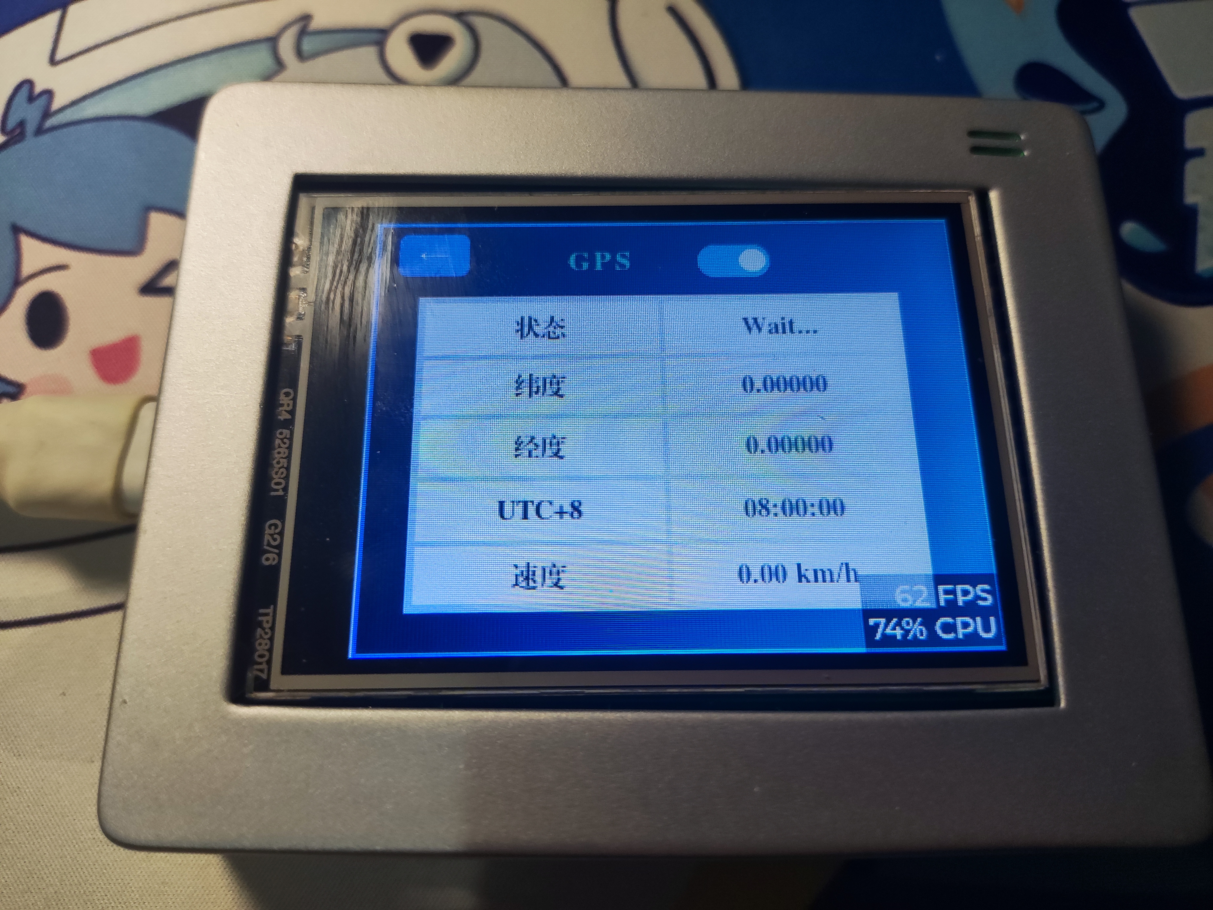
5.2` Regarding the development of the GPS module
, a dedicated interface was developed to display GPS-related information.

After receiving the message via the serial port, the GNRMC data transmitted by the GPS module is decoded:
void HAL_UART_RxCpltCallback(UART_HandleTypeDef *huart)
{
if (huart->Instance == USART1)
{
if (0x0D == UART1_temp[0])
UART1_temp[0] = 0x20; // To prevent
a certain line from not being displayed in the window
if (0x0A == UART1_temp[0])
{
UART1_Rx_flg = 1;
}
u1_data[UART1_Rx_cnt++] = UART1_temp[0];
if (UART1_Rx_cnt >= MAX_REC_LENGTH)
{
UART1_Rx_cnt = 0;
memset(u1_data, '', strlen(u1_data));
}
HAL_UART_Receive_IT(&huart1, (uint8_t *)UART1_temp, REC_LENGTH);
}
if (huart->Instance == UART5) // Only the data in the $GNRMC line needs to be received specifically for GPS data
{
if (UART5_temp[0] == '$')
{
UART5_Rx_cnt = 0;
}
if (0x0D == UART5_temp[0])
{
UART5_temp[0] = 0x20;
}
U5_Rec_temp[UART5_Rx_cnt++] = UART5_temp[0];
if (U5_Rec_temp[0] == '$' && U5_Rec_temp[4] == 'M' && U5_Rec_temp[5] == 'C' && UART5_temp[0] == 0x0A)
{
// End of receiving this line
UART5_Rx_flg = 1;
if (strlen(u5_data) + strlen(U5_Rec_temp) > 1000)
memset(u5_data, '', strlen(u5_data));
strcpy(u5_data, U5_Rec_temp);
memset(U5_Rec_temp, '', strlen(U5_Rec_temp));
UART5_Rx_cnt = 0;
Uart_Rece_Pares();
}
HAL_UART_Receive_IT(&huart5, (uint8_t *)UART5_temp,REC_LENGTH);
}
}
void Uart_Rece_Pares(void) // Serial port receive content parsing function
{
// Note the variable type
char *point = 0;
char *nextPoint = 0;
for (uint8_t i = 0; i < 8; i ++)
{
if (i == 0)
{
if ((point = strstr(u5_data,",")) == NULL)
{
return ;
}
}
else
{
point ++;
if ((nextPoint = strstr(point,",")) != NULL)
{
// Store information
switch (i)
{
case 1: // UTC time
memcpy(&gps.UTCTime,point,nextPoint - point);
break;
case 2: // Data validity flag
memcpy(&gps.UsefulFlag,point,nextPoint - point);
break;
case 3: // Latitude
memcpy(&gps.latitude,point,nextPoint - point);
break;
case 4: // Latitude direction
memcpy(&gps.N_S,point,nextPoint - point);
break;
case 5: // Longitude
memcpy(&gps.longitude,point,nextPoint - point);
break;
case 6: // Longitude direction
memcpy(&gps.E_W,point,nextPoint - point);
break;
case 7:
memcpy(&gps.speed,point,nextPoint - point);
break;
}
point = nextPoint;
}
}
}
// Processing data
float latitude = 0; // Store latitude information
uint16_t temp1 = 0;
float longitude = 0; // Store longitude information
uint16_t temp2 = 0;
latitude = strtod((const char*)gps.latitude,NULL); // Convert string to floating-point number
longitude = strtod((const char*)gps.longitude,NULL); // Convert string to floating-point number
// Latitude information processing
// Five-digit latitude information
if ((latitude - 10000.0f) >= 0)
{
temp1 = (((uint16_t)latitude / 10000) % 10) * 100 + (((uint16_t)latitude / 1000) % 10) * 10 + ((uint16_t)latitude / 100) % 10;
latitude = latitude - (float)temp1 * 100;
latitude = (float)temp1 + latitude / 60;
}
else // Four-digit latitude information
{
temp1 = (((uint16_t)latitude / 1000) % 10) * 10 + ((uint16_t)latitude / 100) % 10;
latitude = latitude - (float)temp1 * 100;
latitude = (float)temp1 + latitude / 60;
}
// Longitude information processing
// Five-digit longitude information
if ((longitude - 10000.0f) >= 0)
{
temp2 = (((uint16_t)longitude / 10000) % 10) * 100 + (((uint16_t)longitude / 1000) % 10) * 10 + ((uint16_t)longitude / 100) % 10;
longitude = longitude - (float)temp2 * 100;
longitude = (float)temp2 + longitude / 60;
}
else // Four-digit longitude information
{
temp2 = (((uint16_t)longitude / 1000) % 10) * 10 + ((uint16_t)longitude / 100) % 10;
longitude = longitude - (float)temp2 * 100;
longitude = (float)temp2 + longitude / 60;
}
gps.UTCTime_int = ((uint32_t)strtod((const char*)gps.UTCTime,NULL) +80000)%240000;
gps.latitude_d = latitude;
gps.longitude_d = longitude;
}
Then display in the table
void update_gps_info(lv_timer_t * timer){
#if !LV_USE_GUIDER_SIMULATOR
HAL_UART_Receive_IT(&huart5,(uint8_t *)UART5_temp,REC_LENGTH);
char t0[20],t1[20],t2[20],t3[20],t4[20];
//Check status code
if(UART5_Rx_flg==1) {
UART5_Rx_flg = 0;
if(gps.UsefulFlag=='V')
strcpy(t0,"Wait...");
else if(gps.UsefulFlag=='A')
strcpy(t0,"OK");
lv_table_set_cell_value(guider_ui.app_screen_table_gps,0,1,t0);//status
sprintf(t1,"%.5f",gps.latitude_d);
if(gps.N_S=='N')
strcat(t1," N");
else if(gps.N_S=='S')
strcat(t1," S");
lv_table_set_cell_value(guider_ui.app_screen_table_gps,1,1,t1);//Latitude
sprintf(t2,"%.5f",gps.longitude_d);
if(gps.E_W=='E')
strcat(t2," E");
else if(gps.E_W=='W')
strcat(t2," W");
lv_table_set_cell_value(guider_ui.app_screen_table_gps,2,1,t2);//Longitude
sprintf(t3,"%02d:%02d:%02d",gps.UTCTime_int/10000,gps.UTCTime_int/100%100,gps.UTCTime_int%100);
lv_table_set_cell_value(guider_ui.app_screen_table_gps,3,1,t3);//UTC
gps.speed_d = strtod((const char*)gps.speed,NULL);
sprintf(t4,"%.2f",gps.speed_d*1.852);
strcat(t4," km/h");
lv_table_set_cell_value(guider_ui.app_screen_table_gps,4,1,t4);//speed km/h
}
#endif
}
5.3 Troubleshooting Record Table
The following is a summary table of troubleshooting issues encountered during software development. Each time a small problem was solved, it was recorded. If you encounter problems during debugging, you may want to refer to this table:
Hard fault immediately after entering systeminit. Solution: Use cube programmer to perform a full chip erase and then download the program. There may have been errors in the previous program.
White screen display: Solution: Enable the relevant options in Cortex M7, see https://blog.csdn.net/weixin_66689383/article/details/132046062
In CUBEMX, the power supply for RCC needs to be set to PWR_LDO; otherwise, the chip won't run!
The screen displays a distorted image after DMA is enabled. Reason: The MPU cache in the Cortex-M7 is enabled, causing data inconsistency. Solution: Disable DCache (this will reduce performance) or add SCB_CleanInvalidateDCache() before and after enabling DMA interrupts
. The program doesn't run after downloading. Reason: A printf statement was added without any redirection; deleting it resolves the
issue. The program displays "no algorithm found for" during download. Solution: [https://blog.csdn.net/qq_22433397/article/details/122223508](https://blog.csdn.net/qq_22433397/article/details/122223508).
An error occurs after writing data to SDRAM and then reading it. Solution: Adjust the SDRAM clock cycle. Currently, the test result without errors is 2 8 6 6 2 2 6. Also, pay attention to the SDRAM configuration: BANK1 9 BITS 13 BITS 3 CLK DISABLE 2 CLK ENABLE 0 CLK.
A memory management error occurred in f_mount when porting FATFS. Cause: Access to prohibited memory. Solution: Change the FATFS device from 2 to 1 in CUBEMX.
FATFS file system failed to remount after creation. Cause: Pitfall of the sizeof() operator. When writing, sizeof(buff) was used, sizeof(buff) read 4, but 4096 should actually be written. When creating the MBR, 0x55 0xAA represents the end of the MBR. The area from 0x1FE to 0x1FF is naturally not written to flash, so the bootloader cannot be found.
After porting FATFS to the main branch, FATFS files could not be opened, but it worked normally in the test branch. Solution: The MPU cache in the cortex_m7 was enabled, causing data inconsistency. Solution: In the MPU settings, set the 512KB area after 0x24000000 to cacheable disabled
. After adding it to FATFS, the screen refresh became sluggish. Cause: After enabling the MPU area 0x24000000 above, cacheable disabled is required. Disabling it causes sluggishness. Solution: Add `SCB_CleanInvalidateDCache()` at the beginning of the underlying QSPI Read and Write functions to clear the DCache and ensure data consistency.
FATFS file size reading error. Cause: The `unsigned int` placeholder was mistakenly written as `%llu` in `printf`, it should actually be `%u`.
LVGL file system enters a hard fault when returning from file read. Cause: `fs_open` returned the address of a local variable; the changed value should be treated as a global variable.
6. Future Update Goals:
Due to other commitments, a version with basic functionality completed is released first. Within three weeks of starting software development, the basic framework of each module has been completed. The subsequent development will focus on further refining the functionality of each part based on these modules. Future development goals are as follows:
| Version Number | Update Content |
| :---: | :---: |
|V1.1| File browser updated to official version, capable of reading files |
|V1.2| Launch map application |
|V1.3| Launch mini-game application |
|V1.4| Develop camera functionality |
|Long-term plan TODO| Able to run AI applications |
7 References & Acknowledgements
The following projects were referenced during the hardware design process:
https://oshwhub.com/lixidixi/stm32h743iit6-development-board
https://oshwhub.com/upoaktreesup/stm32h735igt6-dev
Positioning module reference: During software development, I benefited greatly from the forum https://www.armbbs.cn/. Thanks to the expert "Hardman" for the H7 series open-source code and his enthusiastic help!
Special thanks to JLCPCB for providing consumable support through their Spark Program! 8. Appearance code open-source address : https://github.com/vrxiaojie/STM32H743ZGT6


 京公网安备 11010802033920号

 MI-L6V-IS


