Project Description: This
project initially stemmed from my desire to avoid using a computer, but as inspiration grew during its development, it evolved into its current form.
Demo Video
[Open Source]: After 9 months, I finally completed the mechanical keyboard that embodies all my fantasies. _Bilibili_
Project Features:
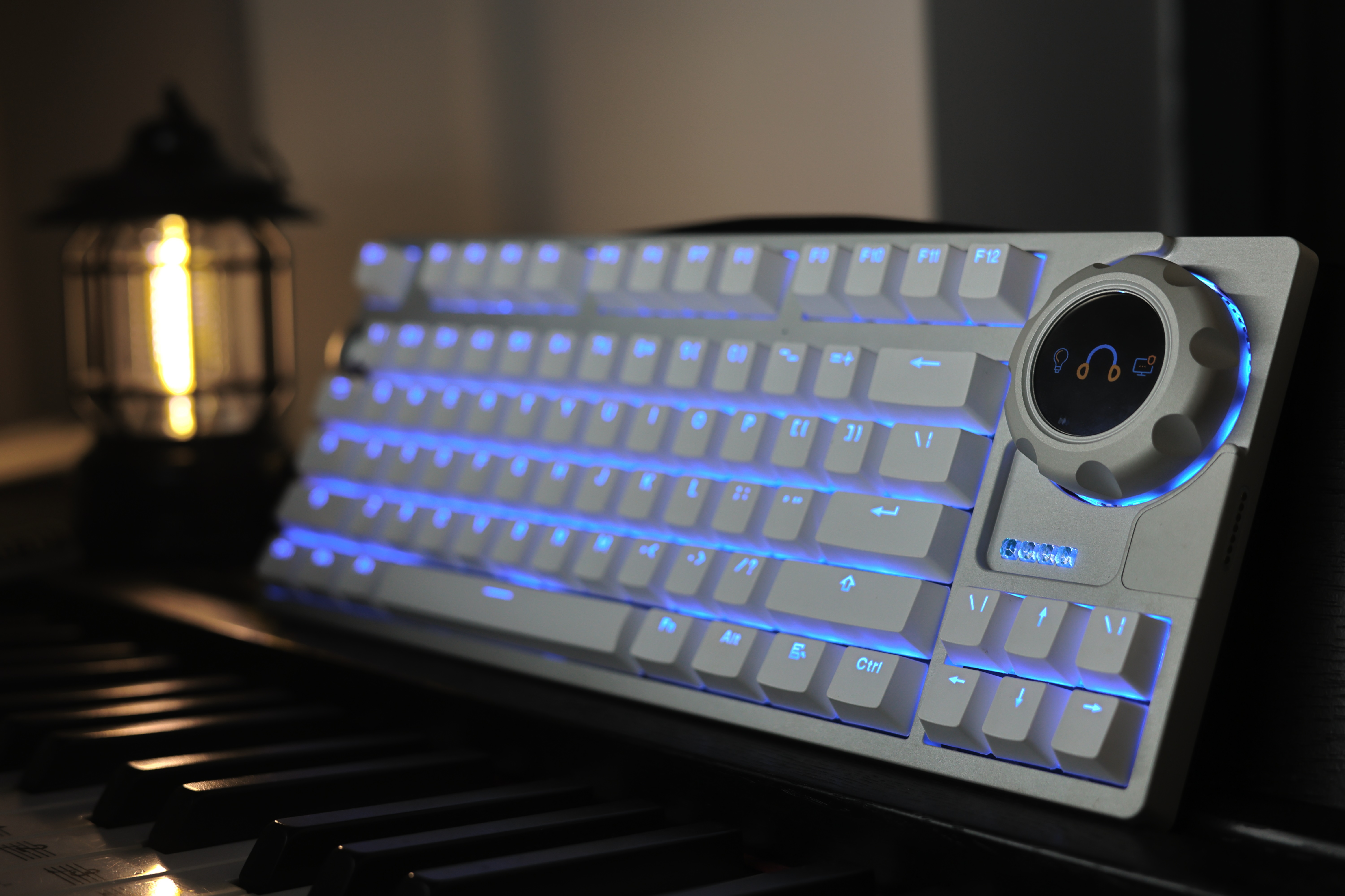
A 4-mode mechanical keyboard supporting Wi-Fi (USB, Bluetooth, Wi-Fi, 2.4G receiver), supports mouse data forwarding, features a magnetic FOC knob, supports SurfaceDial, supports multi-functional magnetic expansion (e.g., a numeric keypad), and supports voice interaction.
Project Progress
: Hardware:
2024-07-23 Completed the second version design of the motherboard and audio board, and prototyped. 2024-07-24
Completed the fourth version design of the knob motherboard, and prototyped.
2024-07-28 Completed the third version debugging of the motherboard; some issues remain with the protection circuit of the magnetic interface. 2024-07-29
Completed 50% debugging of the second version of the audio board.
2024-07-30 Completed the fourth version design of the motherboard, and prototyped.
2024-08-04 Completed the second version of the knob mainboard debugging, now OK.
2024-08-04 Completed the fourth version of the mainboard debugging, now OK.
2024-08-05 Completed the PCB manufacturing instructions. 2024-08-05
Completed the electronic component BOM.
2024-08-07 Completed the second version of the audio board debugging; playback is OK, but recording still has issues and needs further adjustment.
2024-08-07 Updated the BOM, removing the receiver antenna component (this antenna is an onboard antenna).
2024-08-12 The second version of the audio board debugging is OK.
2024-08-21 Updated the knob main control memory description in the BOM.
2024-10-15 Updated the specifications of audio board U9, U10, U12, and U13 in the BOM.
Structure:
2024-08-04 Completed uploading all structural drawings.
2024-08-05 Completed uploading of structural fabrication instructions (in the 3D file compressed package).
2024-08-05 Completed uploading of 2D drawings of the positioning plate (in the 3D file compressed package).
2024-08-05 Completed uploading of the structural BOM.
2024-08-07 Updated the BOM, added the keyboard battery, and completed the knob antenna specifications.
2024-08-07 Found an issue with the bottom shell file and updated it. For those who have already followed the previous files, you can use glue to attach the magnets.
2024-08-21 Updated the knob motor link description in the BOM.
2024-10-15 Added an M3 screw to the knob BOM.
Software:
2024-08-05 Uploaded the basic test program.
2024-10-15 Updated the keyboard program (all functions except mouse forwarding are complete).
Design Principles:
1. The main controller is the ESP32S3, which integrates WIFI, Bluetooth, USB, ESP-NOW, and IIS.
2. The audio section uses the ES7210 as the ADC and the ES8311 as the DAC. The power amplifier is the NS4150B (referencing the ESP-BOX hardware design).
3. The download circuit uses the CH342F, which has two channels for USB to TTL conversion, corresponding to the keyboard and knob controllers respectively.
4. The USB hub chip is the SL2.1A, and the emulator chip for the USB flash drive is the GL823K.
5. The magnetic interface supports IIC communication. To avoid environmental influences on the IIC bus, each interface has a protection circuit that disconnects the exposed contacts from the internal bus when a valid device is not correctly identified.
6. Key detection uses a shift register method, referencing Zhihui Jun's Hanwen keyboard project.
7. The keyboard key backlight uses the WS2812, and the grille lighting on the back of the keyboard uses a horizontal LED driver IC with LED strips.
8. The knob screen driver is GC9A01.
9. The knob motor driver is TMC6300, and the magnetic encoder is AS5047P.
10. The knob pressure sensor is HX711 with a strain gauge.
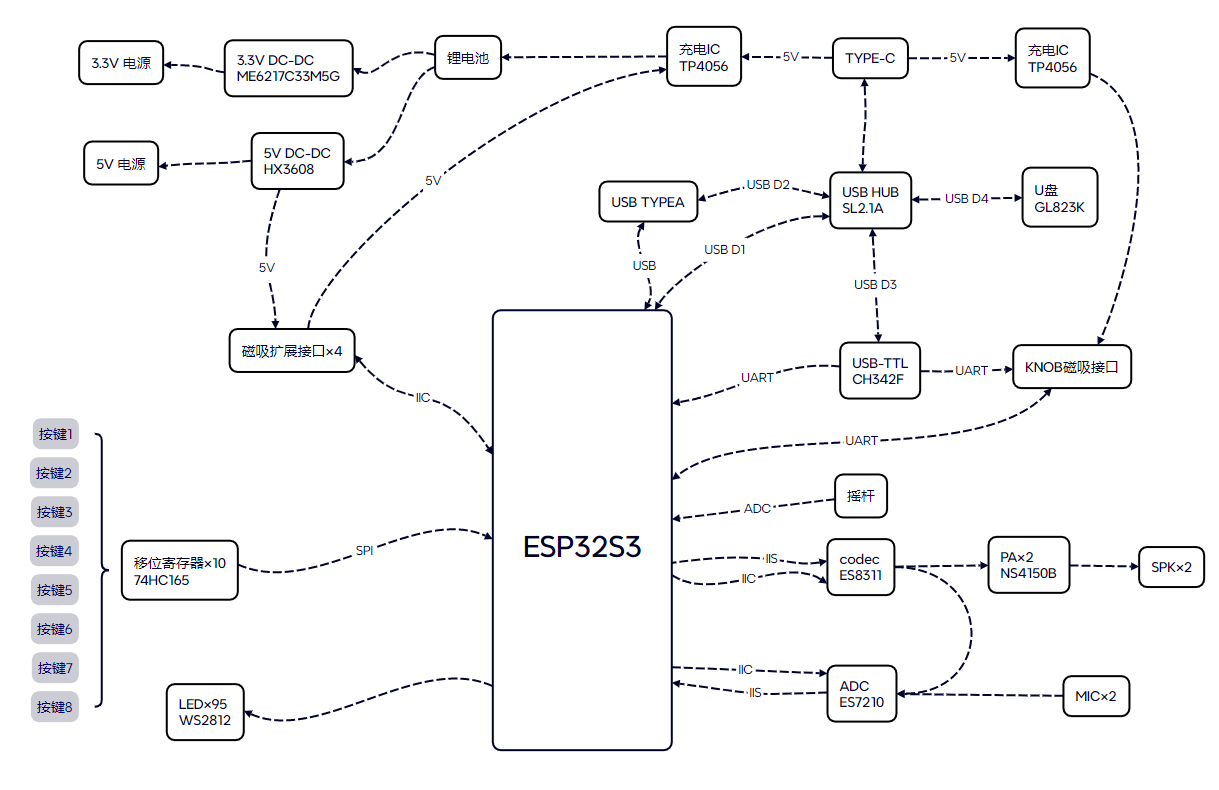
The keyboard hardware block diagram is shown below:
The knob hardware block diagram is shown below:

Analysis of individual function principles:
1. Keyboard data forwarding function:
The mouse can be plugged into the keyboard's TYPE-A interface. This interface can connect to the ESP32S3 main controller's USB port via analog switches U6 and U7, as shown below. After connection, the ESP32S3 can read mouse data via USB and then forward it wirelessly. The main controller can forward mouse data to the computer in WIFI, Bluetooth, and ESP-NOW connection modes. In WIFI mode, the transmission distance of the mouse can be greatly increased.

When the keyboard is connected to the computer via USB, the analog switches U6 and U7 inside the keyboard will connect both the TYPE-A interface and the ESP32S3's USB port to the USB HUB. At this time, the TYPE-A interface is equivalent to a direct connection to the computer's USB port, as shown below. It supports not only mice but also any other USB peripherals.

2. Keyboard Expansion Interface Circuit:
The main function of the expansion interface is to establish power and data connections with expansion modules. It supports powering expansion modules, and power-type expansion modules can also charge the keyboard. The keyboard and expansion modules can exchange data via the IIC bus. The circuit supports expansion module identification. Two voltage monitoring chips, U35 and U37, monitor the voltage on pin 6 of the FPC in real time. When a 20K resistor is connected to GND at pin 6 of the FPC on the expansion module side, the voltage at pin 6 is 20K/(20K+10K)×5V ≈3.3V. At this time, U35 is at a high level, U37 is at a low level, and pin 4 of the XOR logic chip U132 outputs a high level. At this point, the entire expansion interface circuit disables internal charging, enables external power supply, and opens the IIC connection, allowing connection of a numeric keypad expansion module, etc. When the FPC pin 6 resistor on the expansion module is left floating or connected to GND with a resistor of other sizes, in short, when the XOR logic chip U132's pin 4 outputs a high level, the entire expansion interface circuit is enabled for internal charging, disabled for external power supply, and disabled for IIC connection. At this time, the charging expansion module can be connected. The expansion interface circuit is shown in the figure below.

Hardware fabrication instructions
PCB board requirements:
1. Keyboard-Main Control Board V4: FR-4 board material, 1.2mm thick, four-layer board, lamination structure JLC04121H-3313 (free), impedance control +/-20% (free).
2. Keyboard-Arrow Key Board: FR-4 board material, 1.2mm thick, double-layer board.
3. Keyboard-Audio Board V2: FR-4 board material, 1.0mm thick, four-layer board
. 4. Keyboard-Indicator Board: FR-4 board material, 1.0mm thick, double-layer board.
5. Keyboard - Magnetic Interface: FR-4 board, 1.6mm thick, double-layer board.
6. Keyboard - Knob Magnetic Adapter Board: FR-4 board, 1.0mm thick, double-layer board.
7. Keyboard - Round Light Board: FR-4 board, 1.0mm thick, double-layer board
. 8. Keyboard - USB Board: FR-4 board, 1.0mm thick, double-layer board.
9. Knob - Main Control Board V4: FR-4 board, 1.0mm thick, 4-layer board; for manual soldering, immersion gold treatment of the pads is recommended.
10. Knob - Battery Light Board: FR-4 board, 1.0mm thick, double-layer board.
11. Knob - Screen Cable Adapter Board: FR-4 board, 1.0mm thick, double-layer board.
12. Receiver: FR-4 board, 1.0mm thick, 4-layer board; for manual soldering, immersion gold treatment of the pads is recommended
. PCB Bill of Materials:
See attached BOM, Keyboard - Main Control Board V4, Knob - Main Control Board V4 Materials marked on the schematic or PCB can be used; other boards must adhere to the BOM.
Software Description
: 1. The keyboard software uses the ESP-IDF development environment, including voice, four communication modes, key scanning, etc.
2. The knob software uses the vscode+platformio development environment, including lvgl, SimpleFOC, etc.
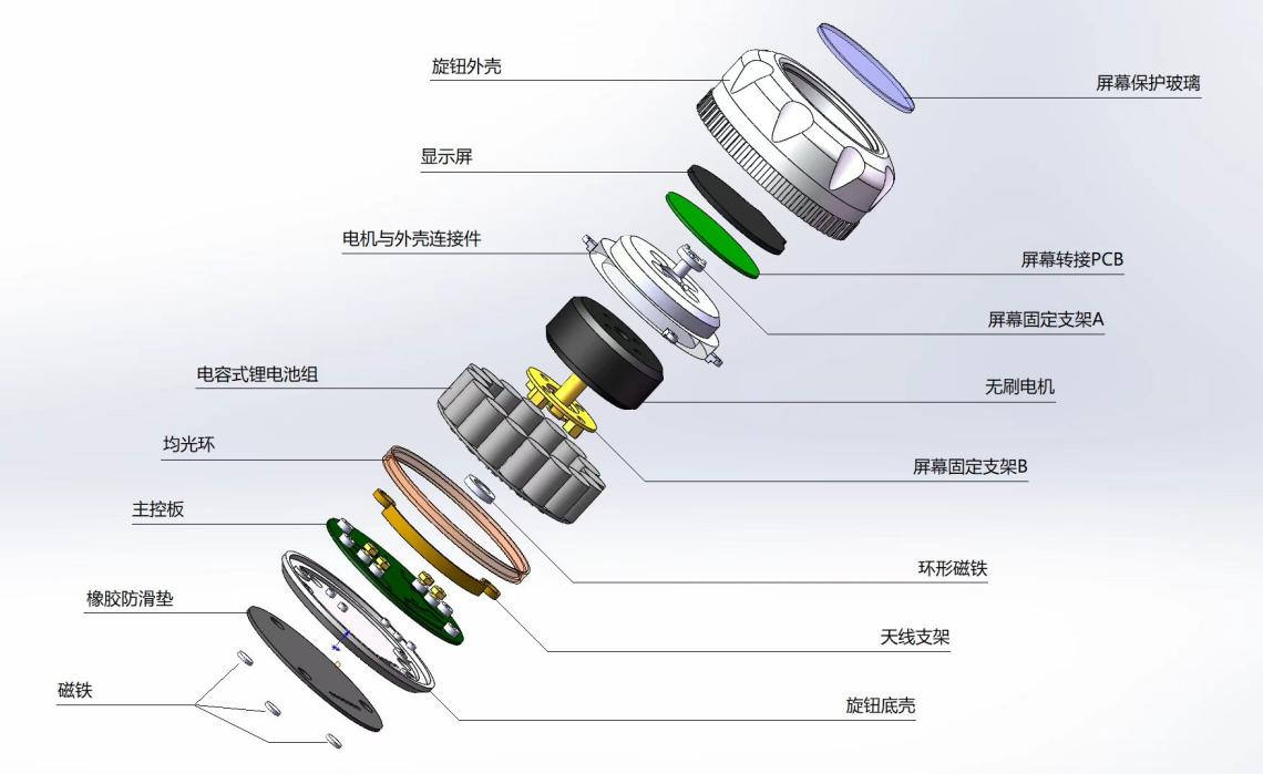
Structural Assembly Diagram:
1. Knob Part:
2. Keyboard Part: No
reference project
. 1. The idea of applying a brushless motor to the keyboard and using a shift register to detect key presses comes from Zhihui Jun's Hanwen Keyboard project. 【Hanwen】HelloWord-Keyboard - JLCPCB EDA Open Source Hardware Platform (oshwhub.com)
2. The idea of combining SmartKnob with SurfaceDial comes from Dingding Mushi's X-Knob project. GitHub - SmallPond/X-Knob: X-Knob - A smart knob based on the LVGL UI library, supports Smart Home (MQTT) and Surface Dial (BT) // Force feedback smart knob under the LVGL UI framework (smartknob + X-TRACK)


 京公网安备 11010802033920号

 1N6291AC


