Additional information: This project has an advanced version: Switching Power Supply Experiment - LCSC Open Source Hardware Platform (oshwhub.com)
UC3842 Switching Power Supply
Design Parameters:
VIN = 220V Frequency = 50Hz Vacmin = 85V Vacmax = 265V
Vout = 12V Iout = 5A Pout = 60W
Operating Frequency fs = 100KHz
Efficiency = 80% Pin = 75W Some random thoughts
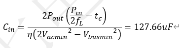
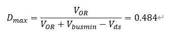
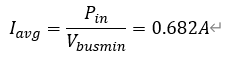
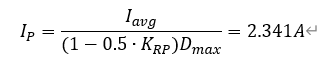
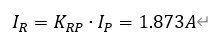
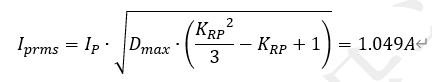
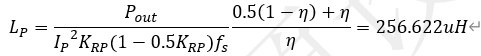
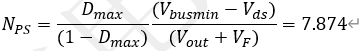
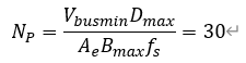
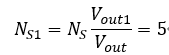
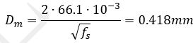
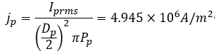
on the design process : Designing a flyback power supply is essentially about three things: transformer, voltage loop, current loop, and loop compensation. Once these three are calculated correctly, there shouldn't be any problems. This design process does not include EMI; the equipment required for that is too high-end, and I can't afford it. You can easily find articles online about how to design it, and it doesn't require too many calculations. In a single-phase bridge rectifier filter circuit, the AC current is multiplied by the square root of 2 after rectification, resulting in Vbus = 311V, Vbusmax = 374V, and Vbusmin = 120V. Adding a 1.5x redundancy, the rectifier bridge's withstand voltage is 562V. Since the pin is 75W, dividing by Vacmin gives a maximum current Iacmax of 0.5A. Adding a 1.5x redundancy, the rectifier bridge's current rating is 0.75A. Based on the above data, directly use the following formula to calculate the filter capacitor: TELESKY GBJ3510 rectifier bridge rectifier 35A 1000V flat bridge single-phase bridge rectifier - tmall.com. Here, tc is the filtering time constant, an empirical value that can be found on Baidu. I used 0.008 seconds, so I chose an 180uf/450V electrolytic capacitor. Original imported black diamond electrolytic capacitors 400/450V/47/56/68/82/100/150/180/220UF - Taobao (taobao.com). Transformer design involves finding the Ap value (for core selection), turns ratio (voltage ratio), and inductance (flyback characteristic). First, calculate the maximum duty cycle, leaving some design redundancy, and use the minimum input DC voltage of 110V for design. Assuming the induced voltage Vor (reflected voltage) of the primary winding of the flyback transformer is 100V, according to the flyback operating principle, the duty cycle is largest when the input voltage is lowest. Calculate the maximum duty cycle Dmax at this point. Next, calculate the average input current Iavg under full load: With a wide input voltage range, the flyback power supply is usually set at low input voltage. The ripple coefficient Krp of the pulsating current Ir and peak current Ip of the primary winding is 0.8. Based on the ripple coefficient and the average input current, the peak current Ip of the flyback primary winding can be calculated as: Then, the pulsating current Ir is obtained as: At this point, the effective primary current Iprms of the transformer can be calculated as: Using the formula for calculating the magnetizing inductance of the flyback transformer, the magnetizing inductance Lp of the primary side of the transformer is obtained as: Based on the previously assumed primary M... The forward voltage drop Vds of the OS transistor is 4V. Assuming the forward voltage drop Vf of the secondary diode is 0.7V, the turns ratio Nps of the transformer can be calculated using the law of conservation of magnetic flux between the primary and secondary sides. Next, the transformer core is calculated. Taking the window fill factor Ko of the flyback transformer as 0.4 and the current density factor Kj as 3.95, and the magnetic flux Bw of the transformer as 0.2T, the minimum Ap value required for the core is calculated using empirical formulas. Based on this Ap value, with a 2x redundancy, and referring to the core specification sheet, the PQ2625 core is selected. Consulting the core specification sheet, the window Aw = 84.5 and the core cross-sectional area Ae = 118 are obtained for this core. To prevent electromagnetic saturation of the transformer, the average maximum magnetic flux density Bmax is selected as 0.2mT. The number of primary turns Np of the transformer is calculated as follows: Using Nps, the secondary parameters are obtained as follows: The flyback transformer has an additional output winding. The output voltage of this winding is used by the control chip. The designed output voltage Vout1 of the additional winding is 15V. Based on the relationship between the output voltage and the winding ratio, the number of turns Ns1 of the auxiliary power supply winding can be calculated as follows: Next, the wire data is calculated. Due to the skin effect of the conductor at high frequencies, many wires are wound together. According to the empirical formula, the skin depth Dm is obtained as follows: To meet the heat generation requirements of the transformer, the current density is generally set to 4~6A/mm^2. Therefore, the winding diameter Dp=0.3mm and the number of strands Pp=3 can be designed for the primary winding of the transformer. Using these parameters, plus the effective value Iprms of the primary winding current, the current density jp can be calculated. This value just meets the empirical value for natural cooling design heat. Therefore, the number of strands and the diameter of the winding are usable. Based on the transformer's primary and secondary turns ratio and the peak value of the primary current, the peak value Isp of the secondary winding current of the flyback transformer is calculated. Based on the peak current of the secondary winding and the duty cycle of the secondary winding, the effective value Isrms of the secondary winding current is calculated using the effective value calculation formula. This allows us to determine the appropriate winding diameter Ds = 0.4mm and the number of strands Ps = 11. Based on the above data, the current density js of the secondary winding can also be calculated, which precisely meets the empirical value for design heat during natural cooling. After selecting the primary and secondary windings, it is necessary to verify whether the transformer can be wound within the selected winding range. This is determined by calculating the ratio of the sum of the cross-sectional areas of all windings to the transformer frame window. The coefficient Kw, representing the cross-sectional area of all windings relative to the transformer window, is calculated as follows: Typically, in transformer winding design, the winding wires have a certain insulation layer, and insulating tape and retaining walls are added during the winding process. To ensure the windings can be wound successfully and with good economic efficiency, a window coefficient between 0.1 and 0.3 is generally appropriate. Therefore, the calculated window coefficient above proves that the winding selection is relatively reasonable. At this point, the transformer design is complete, including the selection of the transformer core, the design of the primary and secondary windings, and finally, a verification of whether the designed windings can be wound successfully. During the primary MOSFET's off-state, the plateau voltage across the MOSFET's source and drain is the sum of the input voltage and the voltage referred from the secondary winding to the primary winding. Furthermore, the plateau voltage reaches its maximum when the input voltage is highest. The MOSFET's current rating is referenced to Isrms, so the 9R1K2C IPA90R1K2C3 (brand new imported TO-220 900V 5.1A, real photos available - Taobao.com) is selected. During the MOSFET's on-state, the secondary rectifier diode withstands a reverse voltage. When the diode is off, its plateau voltage is the sum of the output voltage and the voltage referred from the primary winding to the secondary winding. Furthermore, the plateau voltage reaches its maximum when the input voltage is highest. The voltage across the diode when it is off is calculated as follows:


Due to the leakage inductance of the transformer secondary winding, the junction capacitance of the diode will generate LC oscillation, resulting in a certain voltage spike when the diode is turned off. Therefore, a redundancy of 1.5 times is reserved, so the withstand voltage is Vdio*1.5 = 92V. Iprms is used as a reference for the withstand current. Therefore, a brand new in-stock SBR20U100CT 20A100V Schottky diode and rectifier TO-220 are selected.
At the same time, the voltage that the auxiliary winding palace diode can withstand is calculated as follows:
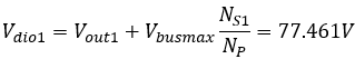
with a redundancy of 1.3 times, the withstand voltage is Vdio1*1.3 = 100V. Because the auxiliary winding is for the chip and consumes very little current, a 1N4148W T4 4148WS 4148WT SOD-123 323 523 surface mount switching diode can be selected. Assuming the flyback
circuit
output ripple voltage ΔVout is 100mV, then at full load, the flyback output load resistance Rout is Vout/Iout = 2.4R. Next, calculate the capacitor value:

due to the influence of ESR internal resistance, replace it with four 470uF capacitors in parallel.
For the RCD circuit,
first assume the transformer primary leakage inductance Lk is within 1% of the magnetizing inductance Lp, and calculate Lk = 2.5uH. Assuming the capacitor's charging time is negligible, and since the capacitor's discharge is linear, and assuming the maximum operating voltage Vmosmax of the switching transistor does not exceed 800V, with some redundancy, we can obtain the voltage Vclamp on the clamping capacitor.

Then, using the RCD circuit absorption formula, we calculate the clamping resistor Rc and the clamping capacitor Cc.

Incidentally, we calculate the clamping power Pclamp.
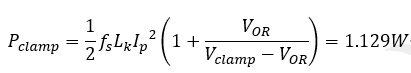
Based on these calculations, we select a 2W 100KR resistor and a 330pF capacitor. The clamping diodes are selected as FR107 1A/1000V through-hole DO-41 fast recovery rectifier diodes (50 units) with a withstand voltage of 1000V.
The
following diagram is a block diagram of the peak current control transfer function of the UC3842. To understand how to design the peripheral circuits and optocoupler feedback circuits of the UC3842, it is essential to understand the relationships between these functions. The specific principles will not be discussed further here.

The transfer function for peak current control of the flyback circuit is

Gvd(s), which is the transfer function from a specific duty cycle d(t) to the output of the flyback circuit

, where Nt = 1/Nps, Cout is the output capacitor, Resr is the esr resistance of the output capacitor, Lp is the magnetizing inductance of the transformer, D is the turn-on duty cycle, D' is the turn-off duty cycle, and Rout is the output load.
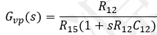
The output voltage, after passing through the sampling feedback circuit Got(s) constructed with optocouplers and TL431, generates a feedback voltage Vot(t) that has a specific relationship with the output voltage. This signal is fed into the designed voltage loop transfer function Gvp(s), which, after voltage loop operations, generates a current loop reference current signal. The primary-side current sampling resistor Rsense converts the current into a voltage signal, which, along with the current loop reference current Vfb(t), generates the control duty cycle d(t). The duty cycle d(t) acts on the flyback transfer function Gvd(s) to output the specific voltage Vot(t).
From Gvd(s), the transfer function from Vfb(t) to Vo(t) can be derived as:

where Ak = 1/3, and other values are given below:
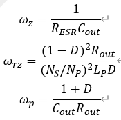
For the peak current transfer function, wz is the zero generated by capacitor Cout, wrz is the right half-plane zero under peak current control, and wp is the output filter pole.
Next, according to the UC3842's internal peak current protection point of 1V, the maximum output current we need is 5A, so Rsense is equal to 1/5 = 0.2R.
Using MATLAB, we can obtain the Bode plot of the power supply before compensation:

From the image, we can see that there are two crossover frequencies, one at 500Hz and the other at 1.4MHz, but its gain curve curves upwards in the high-frequency range, indicating an unstable system.
The compensator
first performs voltage loop compensation.
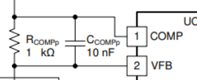
A compensation pole is needed at the frequency of the right half-plane zero or ESR zero (whichever is lower). Calculate fesrz using wz (the capacitor's ESR zero), and then set the resistor to 1KR to obtain a capacitor of approximately 10nF.


Based on these parameters, the voltage loop transfer function from input to output can be obtained as follows:
Then, the transfer function of the optocoupler and TL431 is calculated.

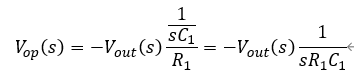
First, assuming the primary current of the optocoupler is I1(s) and the output voltage of the TL431 is Vop(s),

the relationship between Vop(s) and the output voltage Vout(s) calculated according to the op-amp working principle is:
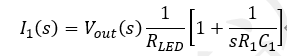
Substituting into the above formula and simplifying, we get I1(s):
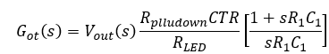
Then, based on the CTR parameters of the selected optocoupler, i.e., the primary-secondary current ratio, which can be found in the manual, the voltage Got(s) across the secondary pull-down resistor Rplludown can be calculated as follows:

Substituting I1(s) into this formula and simplifying, we can obtain the transfer function from Vout(s) to voltage Got(s) as follows:
In this formula, the unknown parameters are Rplludown, Rled, R1, and C1.
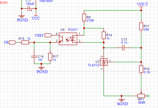
In this diagram, the parameters that need to be set include R11, R18, RP1, R9, R14, and C3.
When the output voltage is 12V and the reference voltage Vref of the TL431's R port is 2.5V, let's assume R11 = 20KR. Using a resistor divider, we can calculate R18 = 5.253KR. Therefore, we choose 5.1KR for R18 and 500R for RP1. R14 is the minimum operating current setting resistor for the TL431. Here, we set the minimum operating current of the TL431 to 1mA, while the voltage across the primary diode of the optocoupler is 1.2V. For ease of selection, we calculate the operating current of the TL431 as 1.2mA, so R1 = 1.2/1.2m = 1KR. To obtain a better phase margin, let's assume the pull-down resistor R17 of the optocoupler transistor is 10KR and the feedback capacitor C13 is 100nF.
Substituting the crossover frequency fc into Gvv(s), the gain of the open-loop transfer function before compensation is calculated as follows:

For analog control flyback circuits, the closed-loop bandwidth (crossover frequency) is generally configured at 1/10 of the switching frequency. Since the flyback switching frequency is 100kHz, the crossover frequency fc of the closed-loop transfer function can be configured as 10kHz.
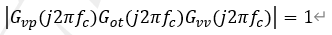
To ensure that the gain of the closed-loop transfer function at the crossover frequency fc is 1, corresponding to a dB value of zero, the following condition must be met:
Substituting gainvv, we can

obtain the equations of Got(s) (remember to substitute the known data) and Gvd(s), which allows us to calculate R9 = 287R.
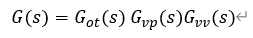
Based on the previous analysis, the overall closed-loop transfer function of the flyback is G(s).
The Bode plot is calculated using MATLAB, as follows:
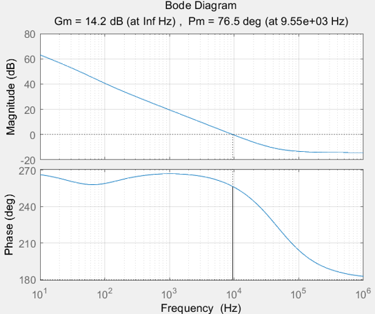
As shown in the figure above, the crossover frequency in the compensated closed-loop transfer function is 9.55kHz, very close to the designed 10kHz. The overall phase margin is 76.5 degrees, the gain margin is 14.2dB, and the gain at 100Hz is 40dB. The system exhibits good stability characteristics and also effectively suppresses the 100Hz bus ripple voltage. It should be noted that this design uses an iterative method. If the phase margin of the obtained flyback closed-loop transfer function is not greater than 45 degrees and the gain margin is less than 7dB, it indicates that the aforementioned parameter assumptions are inappropriate. The initial parameters related to the voltage loop, such as R14 and C13, need to be adjusted until the phase margin and gain margin of the generated closed-loop transfer function meet the requirements.
Typically, the criteria for the closed-loop stability of a switching power supply are as follows:

The parameters are basically calculated, and the results can be verified using PSIM simulation. When
testing the
AC-DC converter with an oscilloscope, it's important to note that the oscilloscope's GND pin is connected to one of the two mains power lines. Therefore, it cannot be directly connected to the UC3842's GND pin, as this will cause a trip. The solution is to add an isolation transformer.
Efficiency testing (which also shows voltage regulation) revealed that
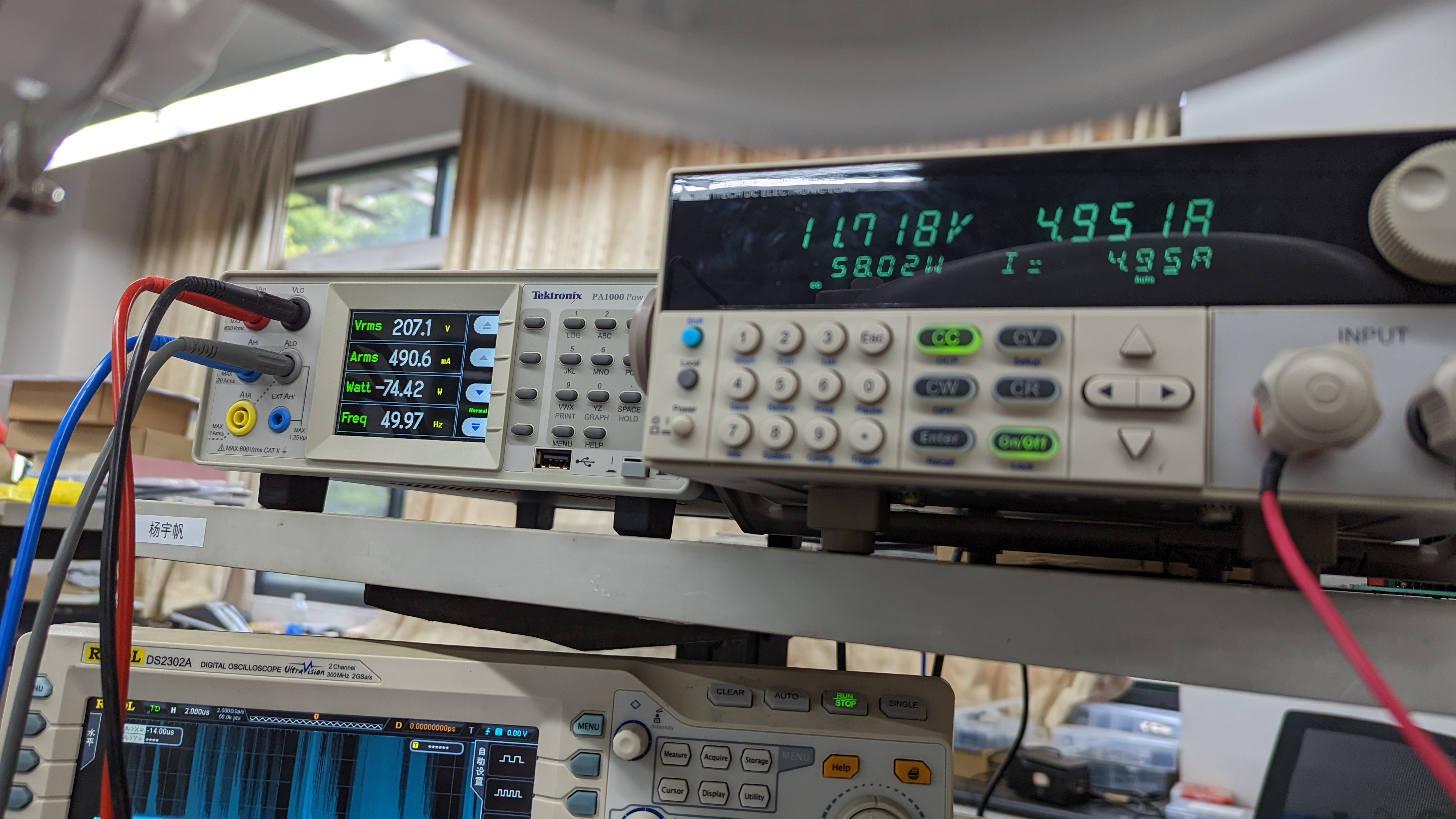
the output voltage wasn't very stable. My MOSFETs didn't have heatsinks, which may have caused excessive temperature drift. However, the efficiency was around 80% in calculations and also around 80% in the actual circuit, indicating relatively stable performance.
Ripple testing showed the dynamic drive output
during startup – source-drain voltage (these tests will be supplemented later). Some design flaws (some cited and commented on): The safety clearance on the PCB is insufficient. It's fine for casual testing with an isolation transformer, but connecting it to mains power is not compliant with regulations. Why is it drawn so compactly? Because if the board were larger, LCSC would charge a prototyping fee. The ACN and mounting screw holes are too close together; they should be designed with more space. Most flyback power supplies in industrial products have a withstand voltage of 650V. Generally, the withstand voltage of the MOSFET used is 90% of the voltage specified in the MOSFET datasheet. Taking a 650V MOSFET as an example, 6500.9 = 585V, and 585V > 470.017. 650V MOSFETs are relatively easy to buy, and their internal resistance is acceptable. Choosing a 900V MOSFET results in alarmingly high internal resistance. An isolation probe can be used to test the actual peak voltage of the MOSFET's drain-source (DS) to check for potential breakdown risk. Avoid copper plating in the high-voltage section and design a safety X capacitor discharge resistor (two approximately 1MΩ resistors, 1206 packages, connected in series and then in parallel across the safety X capacitor). The startup resistor doesn't need to be very large; a 0603 resistor is sufficient, as it doesn't handle large current. Please feel free to comment on any unreasonable or problematic aspects of my design. I will add them to this section for reference and supplementation . The transformer winding information is in another project; those interested can take a look.


 京公网安备 11010802033920号

 1.5KE47E3/70


