As an electronics enthusiast, have you ever encountered this situation:
insufficient power supply to your computer's USB port, or backflow caused by parallel power supply failure, resulting in burnt-out USB ports? You
painstakingly solder a board, plug it in, and power it on, only to find that a short circuit elsewhere (like the backlight) causes excessive current in the USB port.
You might want to directly determine if the board is soldered correctly by
checking the power-on current. You could connect multiple USB devices and easily turn a specific USB port on or off
. Yes, this is the pain point I've encountered in the past two years of building electronics. Currently, my computer's USB ports can only output about 200mA of current; exceeding that results in errors, most likely due to backflow failure.
So, to meet my specific needs, I created a multi-functional USB hub
demonstration video:
https://www.bilibili.com/video/BV1LdtMe1E3S/
Main control section: uses an ESP32S3 module, plus a 4-inch 86-pin touchscreen as the interaction interface. Current
and voltage acquisition section: uses four INA226 chips to acquire four different voltage and current signals, transmitting them to the main control via I2C bus.
USB hub section: uses a CH334R chip, with four USB ports. Hub chip
power supply section: Supports 12V DC IN and PD spurious power supply. The PD spurious chip uses CH224K.
Electronic switch section: Uses SY6288CAAC 2A switch chip to control the VBUS of the 4 USB ports respectively.
Other: Four additional RGB LEDs are added to display the current status of each USB port (as an ambient light group).
The PCB is divided into a core board and a HUB board, facilitating future replacement of other screens or main controllers (such as long strip screens).
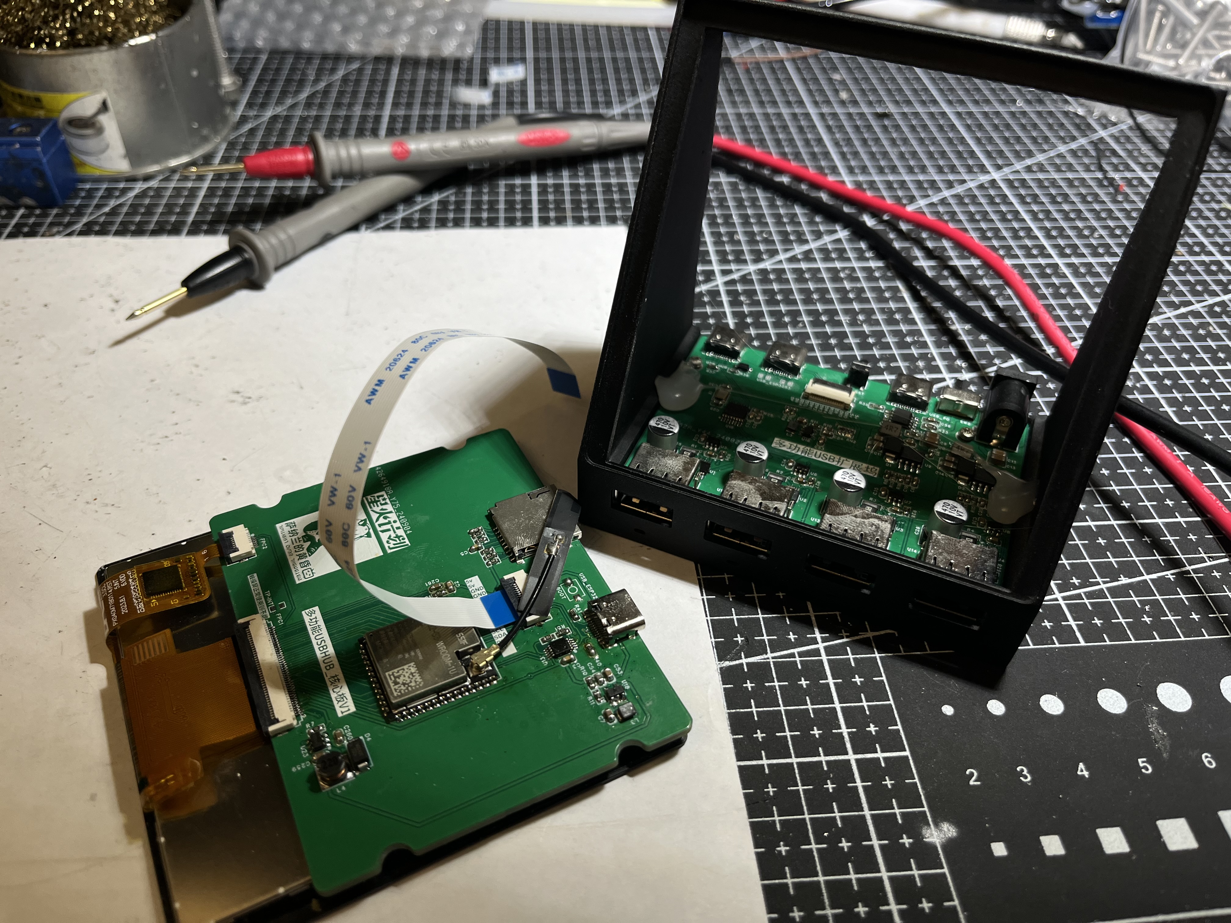
The screen supports multiple 4-inch touchscreens, both independent and integrated touchscreens.
Independent touchscreen models are verified. One example is the single-cable model from Taojingchi (https://item.taobao.com/item.htm?ft=t&id=757571286108&spm=a21dvs.23580594.0.0.1d292c1bCTukzD)
, and another is the 3.95-inch LCD screen/4-inch square screen/smart home RGB interface/resolution 480*480+86-cell IPS from Bohu (Taobao.com). The initialization codes for these two screens are different; macros
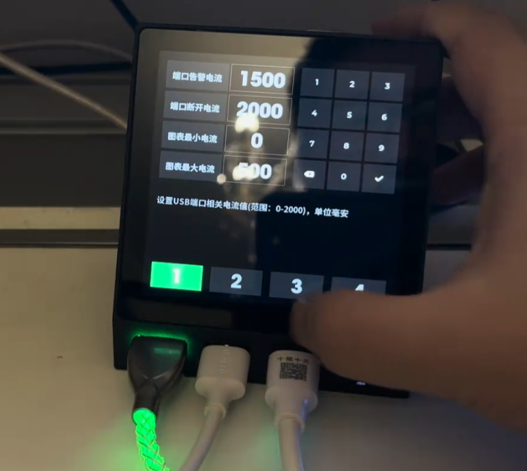
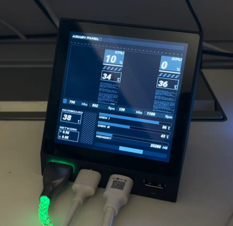
need to be modified in the source code. The HUB screen display is divided into four areas (buttons): 1, 2, 3, and 4, corresponding to the four USB ports on the left . Each USB port has four states. 1. Initialization failed: The button will not display anything, and the RGB light below the port will not light up. 2. Normal: The button will display current, voltage, and power normally. The RGB light below the port will change from green (0mA) to red (1000mA and above) according to the current value. 3. Manual shutdown: The button will have a gray background, and the RGB light below the port will be off-white. 4. Overcurrent warning: The port's digital display and current line graph will turn orange-red, and the RGB light below the port will be blue. 5. Overcurrent shutdown: The port will be disconnected and turn red. To reopen the port after overcurrent shutdown, press the switch once to enter manual shutdown mode, and then press the switch again to return to normal mode. The RGB light below the port will then be purple. Swiping left on the page will take you to the settings page, where you can individually set the four current attributes for each port (alarm current, disconnect current, minimum current in the graph, and maximum current in the graph) using the number buttons 1, 2, 3, and 4 below. Switch current setting for port alarm current: When the port current reaches this value, it enters overcurrent alarm state . Disconnect current: When the port current reaches this value, it enters overcurrent shutdown state. Minimum and maximum current chart: Set the minimum and maximum values of the Y-axis for the real-time current line graph . You need to press the checkmark on the virtual keyboard to trigger saving. When current monitoring is not needed in daily use, you can switch to the following APP and use the device as a secondary screen for the AIDA64 ambient group . This project obtains information from AIDA64's RemotePanel, parses it, and displays it through a custom UI. Run AIDA64 on the computer and set up the RemotePanel as required. On the device side, set up the computer's IP address (both need to be on the same network segment). Unique meter animation effects have been added to CPU and GPU usage, and a line graph effect that changes over time has been added. Animation effects have also been added to hard drive and memory usage. Dynamic weather clock : The weather clock in this project is the same as the one used in the previous iCRT project. The weather animation in this project comes from the HTC SENSE weather animation found online. HTC's mobile phone business has been discontinued for many years. If HTC informs me that it cannot be used, please let me know and I will delete it immediately. The weather updates every 3-5 minutes and currently comes from my Gaode API. If you have your own API, you can apply for it and fill in your usage. When the weather changes, there will be a smooth switching animation. In terms of clock, it includes the display of Gregorian calendar and lunar calendar, as well as common holidays and the 24 solar terms. MJPEG playback uses the latest and fastest SIMD decoding, which is the fastest decoding that the ESP32-S3 can do, 50-80% faster than ordinary decoding libraries such as JPEGDEC. The S3 is really struggling to drive this large screen RGB, so MJPEG playback is about 12 frames. It is recommended to set up some simple picture albums to play pictures. There is a gradient effect when switching. On all pages (except the settings page), swipe up to open the menu, click the menu to enter the corresponding function settings page, and click the arrow in the upper left corner to open the menu. Important Note for Replicas: Do not buy INA226 chips from disassembled devices; actual testing shows a failure rate of over 30%. If you encounter inaccurate readings or no display, it is recommended to replace the chip. For example, chips from LCSC are very stable. Thanks to LCSC for supporting the Spark Program. To avoid 5V backflow into the computer, do not connect the DC IN and PD IN during programming. Unplug the USB after programming and then reconnect it. You can use your own USB 1 or 2 ports to directly connect the core board with a USB cable for programming. Do not plug in the PD's USB and DC IN ports simultaneously. Although the switch supports two switching modes, it cannot be guaranteed that a short circuit between the 12V and PD's VBUS ports will not occur when the switch is toggled. Therefore, only one USB port should be connected at a time. The electrolytic capacitor capacity is not limited to 150uF; I soldered 470uF myself, and I feel the larger the better. The 0805 capacitors and resistors for the PD decoy port can be replaced with 0603 capacitors. The reason for using 0805 is twofold: firstly, it's copied, and secondly, others say that larger packages have higher withstand voltage. The 3D printing price for the casing is approximately 26 yuan (9600 resin). Source code containing a fully functional USB HUB page is available for download here and will be continuously updated.


esp32s3_usb_hub: Pure code for the ESP32S3 USB HUB METER, including complete USB HUB current meter functionality. The PCB and casing are open source on LCSC Open Source Plaza (gitee.com).
For those interested in building one, we recommend joining our DIY discussion group: 739444215.
====================================================================
Update:
Many people have already completed this (2024-11-05). If it proves useful, that's encouraging.
During the replication process, I encountered some common pitfalls, which I've documented here.
1. The core board's touchscreen I2C lacks pull-up resistors; these are located on the hub's baseboard. Therefore, if only the core board is connected, the startup process may get stuck at the I2C initialization stage for a long time.
Solution: Use an expansion board. Alternatively, you can modify the schematic yourself and add pull-up resistors to the I2C SDA and SCL lines of the core board.
2. The sampling resistor is 10 milliohms, called an alloy sampling resistor, specifically 10 milliohms (10mΩ) (R010), not 10 megaohms. Some replicas are sold as 10 megaohms, causing the system to interpret this as a large current and directly cut off the USB port.
3. If the corresponding INA226 address is not detected upon startup, the corresponding button will not be displayed. This can be used to determine which chip is faulty (or not soldered properly).
4. If only the programmed USB port is plugged in without the rear power supply, the current to ports 3 and 4 flows through the inductor; incorrect values are normal.
5. The shell step file has been provided in the group; you can modify it if needed.


 京公网安备 11010802033920号

 VI-JT3CY


