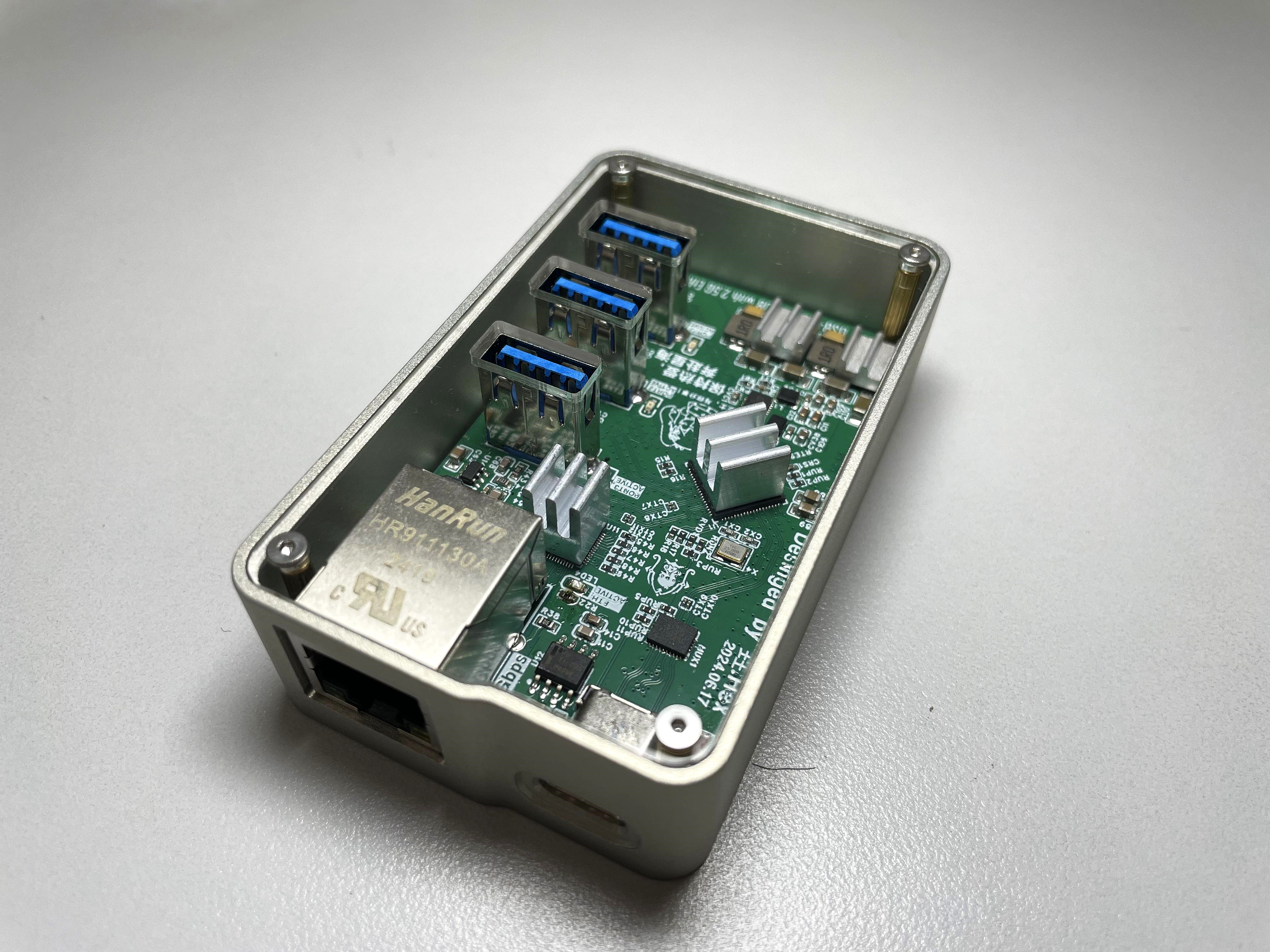
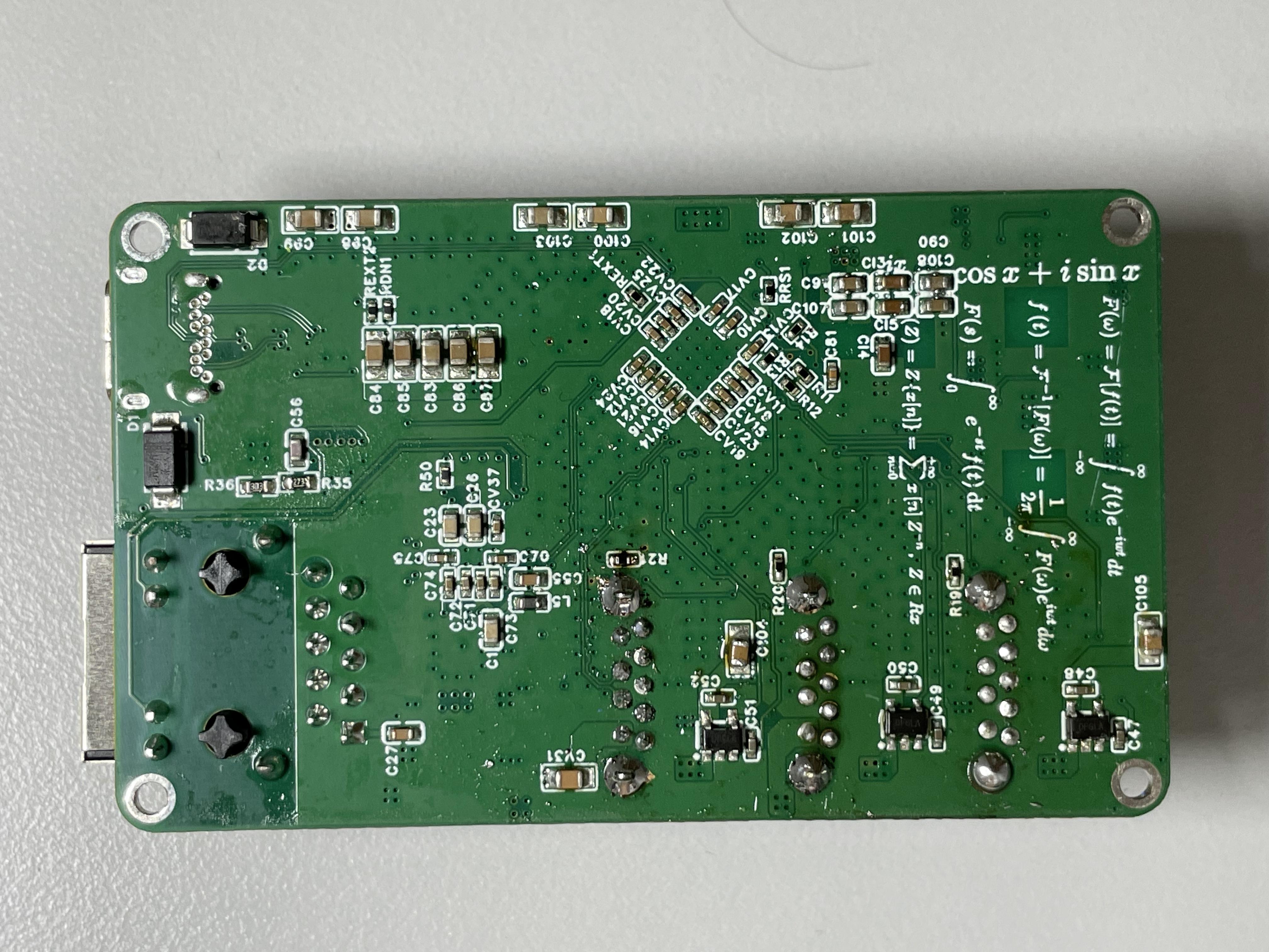
 PCB soldering display:
 Open Source License :
  as follows: After the user connects the USB data cable to the expansion box, it first passes through the VL160 level-flipping chip to achieve reversible insertion. The USB signal after level flipping is sent to the VL822 hub chip. The VL822 splits one USB into four USBs, with three USB interfaces leading out through the USB-TYPEA connector, and the other USB interface connected to the RTL8156-B Ethernet chip, converting the USB bus into an Ethernet bus.
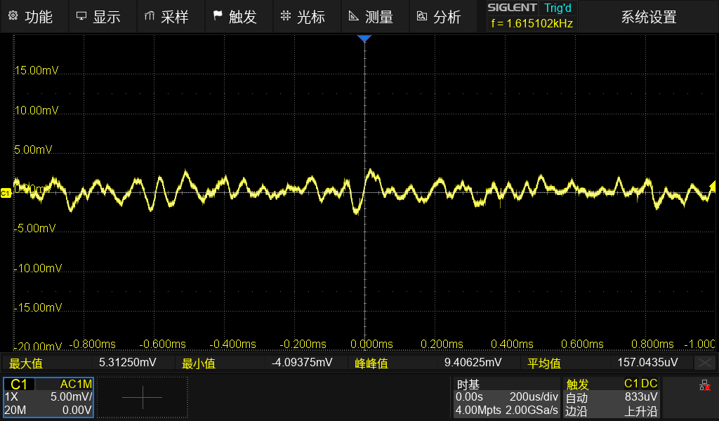
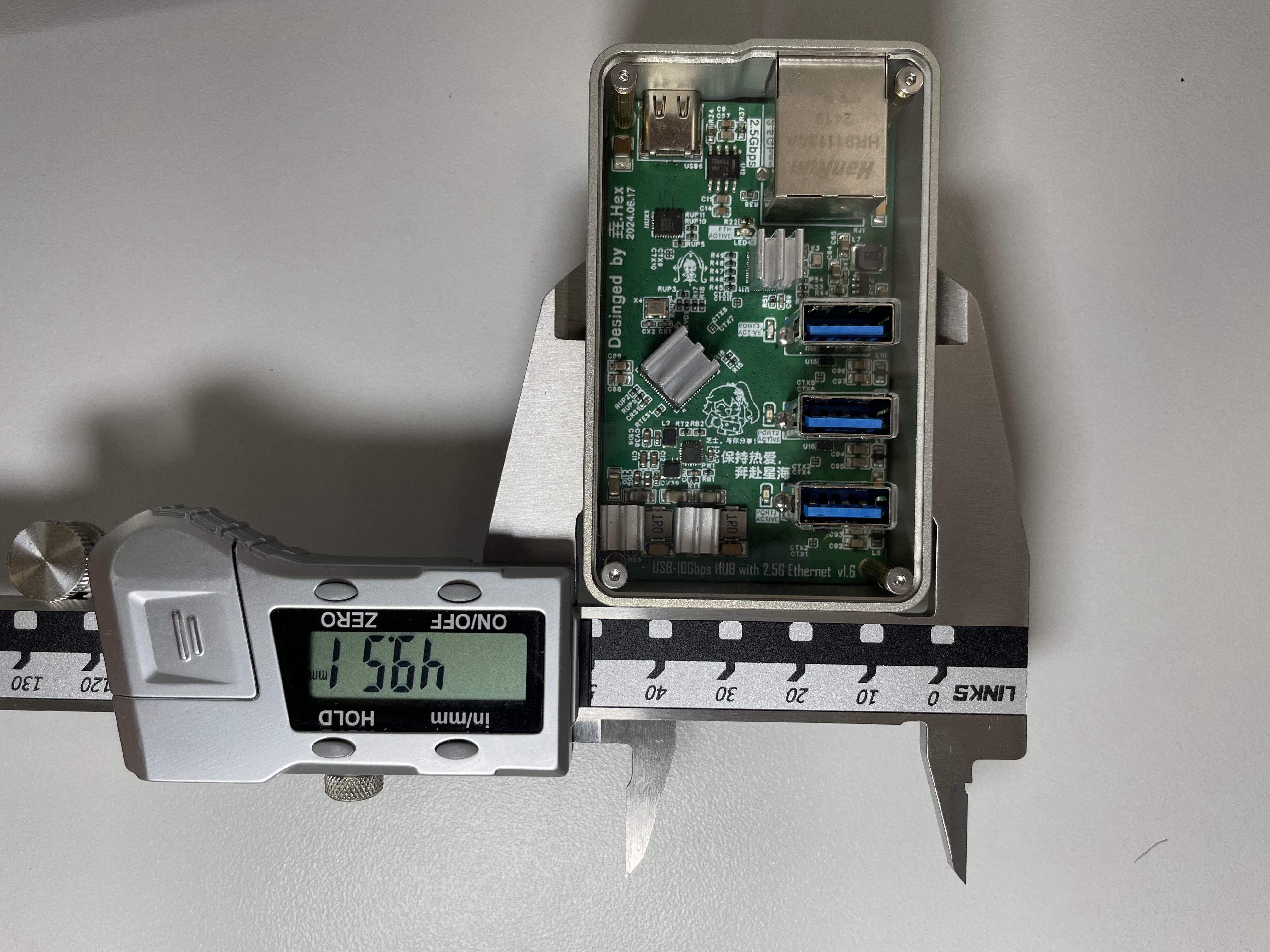
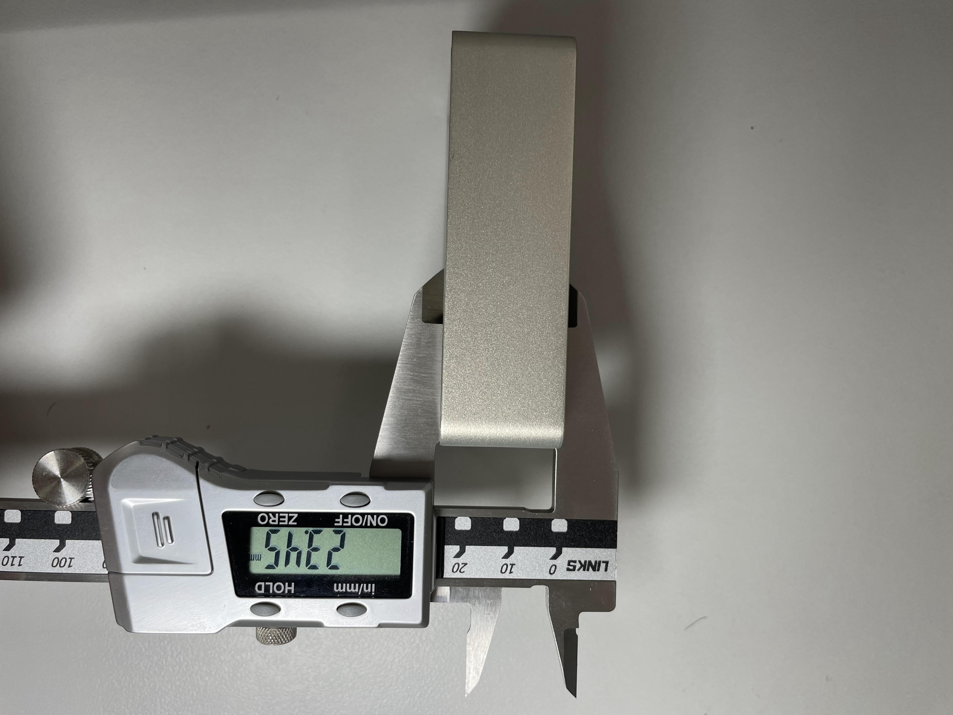
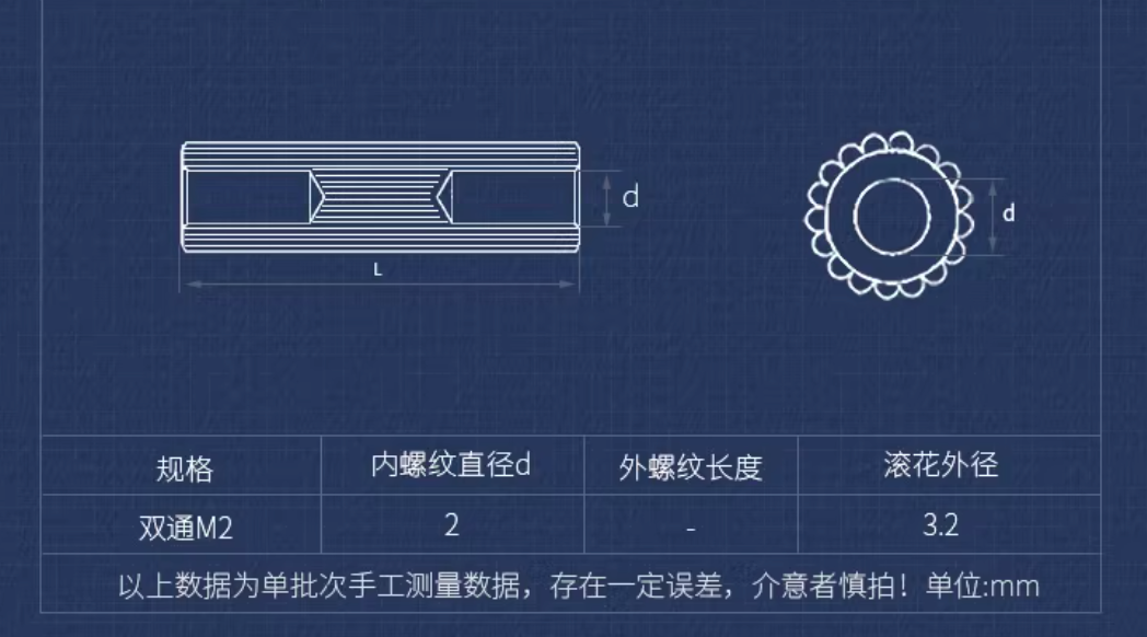
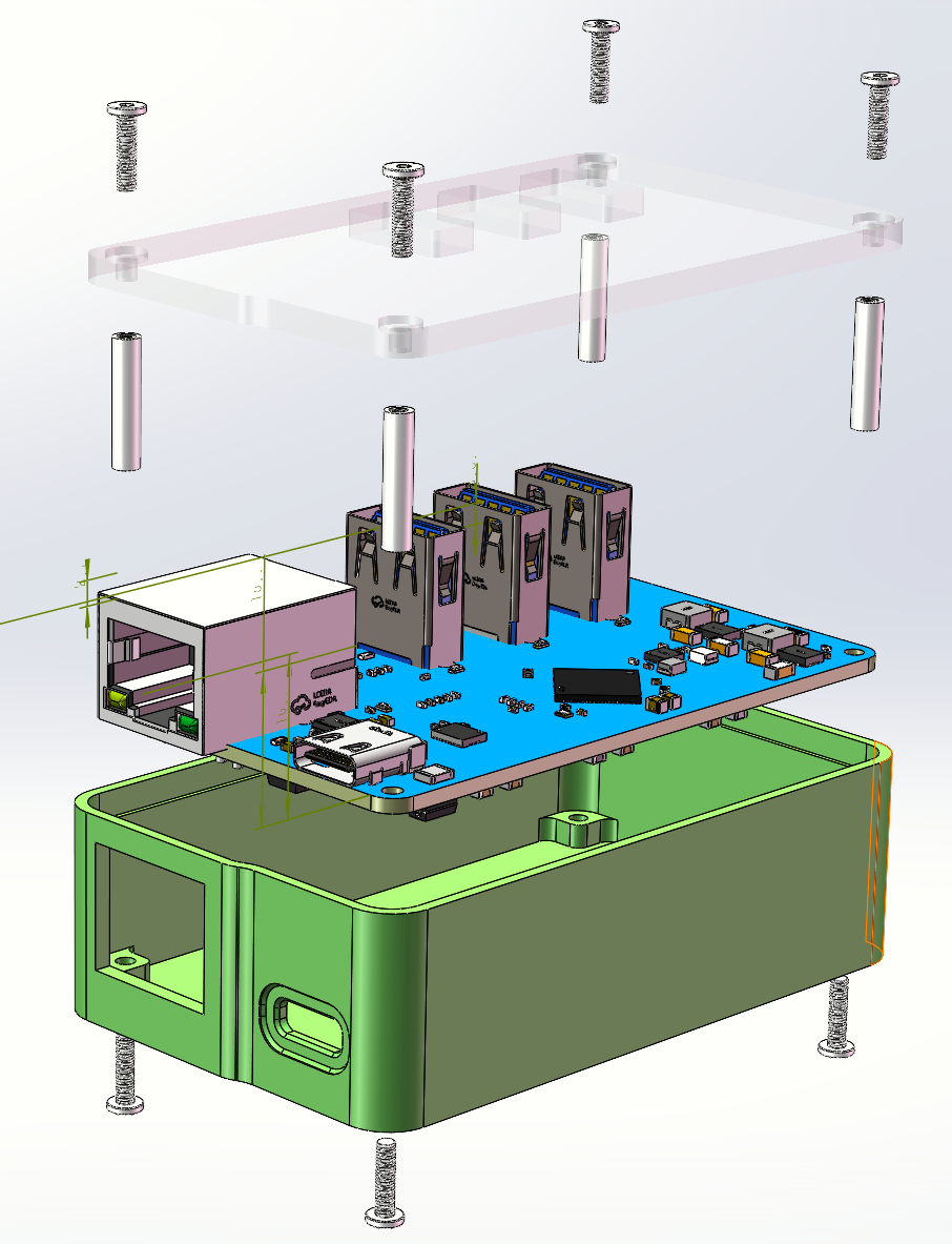
 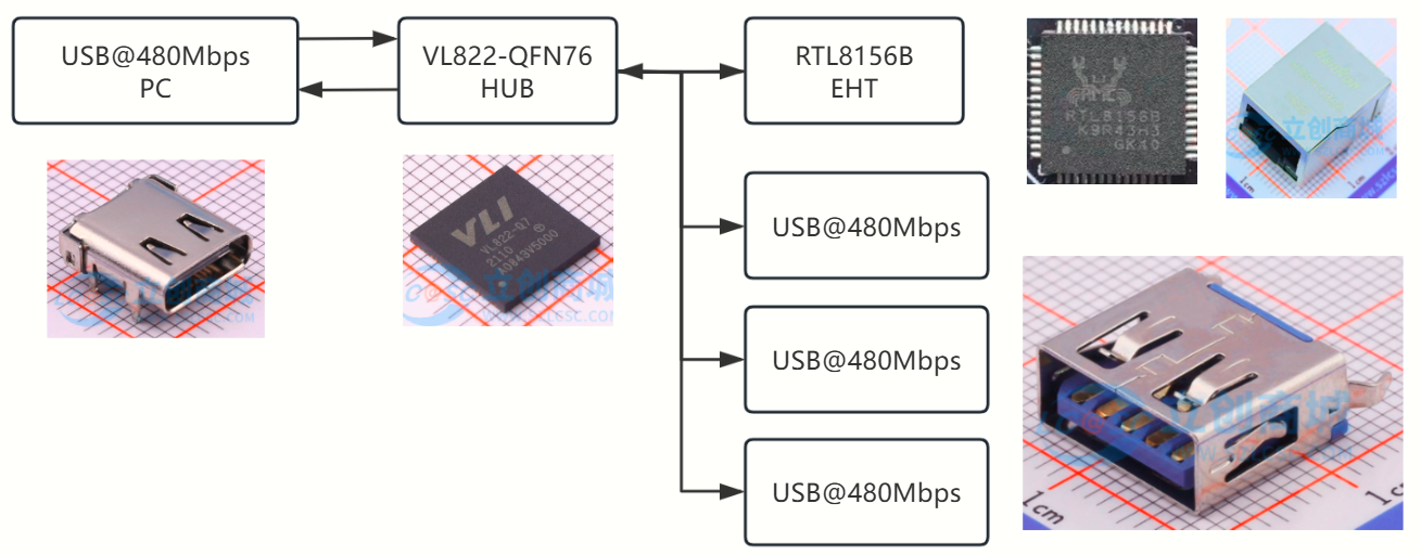 to connecting to a 5Gbps or higher speed interface, connecting to a 480Mbps speed interface bypasses the VL160 level inversion chip; the USB signal directly connects to the VL822 hub, and the maximum speed of the subsequent USB is 480Mbps. The expansion box power supply hardware block diagram shows that the USB-5V is provided by the TYPE-C input interface. After the 5V power enters, it is divided into four paths. The first path sends to the EA3036 power management chip, which is a 3-output buck architecture power chip. This project only uses 2 outputs, converting the 5V voltage to 3.3V and 1.2V for use by the subsequent VL822. The second path sends to the TPS63020 chip, which is a buck-boost architecture power chip. It stabilizes the input 5V voltage at approximately 5.2V before sending it to the next stage circuit. The addition of this circuit avoids voltage drops caused by the internal resistance of the data lines and connectors. The next stage circuit consists of Power over Ethernet (PoE) and the SY628CAAC. The SY628CAAC is a power electronic switch with overcurrent protection. When the downstream load exceeds 2A, the switch disconnects the power supply and alerts the controller to the overcurrent by pulling the OC pin low. The third path sends to the second TPS63020 chip; the downstream of this circuit is two USB output ports. The fourth path sends to the VL160 level inverter chip. Hardware performance testing : TYPE-A interface output ripple test: The TYPE-A interface is left floating, the probe is set to x1, the oscilloscope is limited to 20MHz bandwidth, and grounded using a grounding spring. The no-load output ripple was approximately 7mV, as shown in the figure. The ripple under a 1.2A load was approximately 9mV, as shown in the figure. Test equipment: SDS824X-HD expansion box. Heat test: The USB1 and USB3 ports of the expansion box were simultaneously connected to an electronic load. The electronic load current was set to 1.2A. After being left to stand in an indoor environment for 10 minutes, the temperature was shown in the figure. Interface speed test: The expansion box was connected to the computer's USB@10Gps port, and then the hard drive enclosure was connected to the expansion box. DiskMark software was used to test the read and write speeds of the RTL9210B main controller hard drive enclosure. The results are shown in the figure. Length, width and height test: Replica precautions : In addition to the PCB and electronic components, the following parts also need to be purchased or sampled: Shell: The shell can be processed using CNC or 3D printing. The 3D drawings processed using both processes have been uploaded with the files to the "USB 3.2 expansion box 3D drawings shell" folder with independent voltage regulation power supply on Baidu Cloud. Top cover: Laser cutting acrylic is recommended for the top cover. It is cheap and good-looking. The acrylic thickness used for cutting is 3mm. Of course, 3D printing can also be used. The DWG and STL files have been uploaded to the 3D drawing folder for the USB 3.2 expansion box with independent voltage regulation power supply on Baidu Cloud. Screws : Use M2*8mm screws. (Link not provided to avoid advertising). Parameters look like this: Studs : Use M2*14 double-pass knurled studs. Parameters shown in the image. Assembly: Internal structure of the expansion box shown in the image. Exploded view: PCB fabrication precautions: When ordering the PCB, select JLC04121H-3313 laminated structure, 1.2mm thick. Impedance matching is required. Ethernet characteristic impedance is 100Ω, USB characteristic impedance is 90Ω. Images of the transmission lines requiring impedance matching have been packaged and uploaded to Baidu Cloud. If not using SMT, solder the power chip and its peripheral components first. After powering on, check if all voltages are generated. Only solder other chips after all voltages are generated. The EA3036 chip is relatively difficult to solder; sometimes cold solder joints occur. LEDs 1-4 are port indicator lights, indicating the operating speed of the USB interface. A solid light indicates 10Gbps, a rapid breathing light indicates 5Gbps, and a slow breathing light indicates 480Mbps or lower. The LEDs are packaged in 0603, and their colors can be changed to your preference. When soldering the USB-A connector, ensure it aligns with the silkscreen markings on the PCB; misalignment will prevent the top cover from closing. Other precautions: Some systems may experience insufficient Ethernet uplink speeds, requiring driver installation. The driver file is located in the RTL8156B.10046.20 compressed file in the root directory of Baidu Cloud. Baidu Cloud link : https://pan.baidu.com/s/12DF_AuVvDpFOs8UqOxaP5g?pwd=ovf0 Extraction code: ovf0
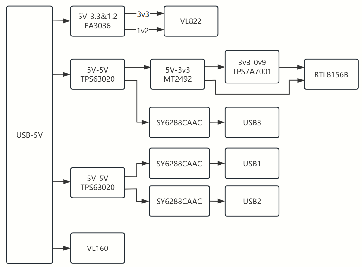


All reference designs on this site are sourced from major semiconductor manufacturers or collected online for learning and research. The copyright belongs to the semiconductor manufacturer or the original author. If you believe that the reference design of this site infringes upon your relevant rights and interests, please send us a rights notice. As a neutral platform service provider, we will take measures to delete the relevant content in accordance with relevant laws after receiving the relevant notice from the rights holder. Please send relevant notifications to email: bbs_service@eeworld.com.cn.
It is your responsibility to test the circuit yourself and determine its suitability for you. EEWorld will not be liable for direct, indirect, special, incidental, consequential or punitive damages arising from any cause or anything connected to any reference design used.
Supported by EEWorld Datasheet
EEWorld
subscription
account

EEWorld
service
account

Automotive
development
community

Robot
development
community

About Us Customer Service Contact Information Datasheet Sitemap LatestNews


Room 1530, 15th Floor, Building B,
No.18 Zhongguancun Street,
Haidian District,
Beijing, Postal Code: 100190
China
Telephone: 008610 8235 0740
 京公网安备 11010802033920号

 PT2126-F4A-RSN2-C


