#Introduction to
the USB2USB keyboard converter base plate, connecting SparkFun Pro Mini/Micro (Atmega32u4) and USB Host Shield Mini module board, replacing the Arduino Leonardo+ USB Host Shield prototype solution.
## About the keyboard converter
By connecting the keyboard to the converter (mapper) and then connecting it to the computer, the keyboard keys can be redefined or new shortcut keys can be defined. There is similar software that can do this, but it is not universal across different computer platforms.
## Others
implement free definition of keyboard keys to improve coding efficiency.
The ICSP and UART interfaces are introduced to facilitate firmware flashing and debugging.
Add voltage conversion and IO level conversion to facilitate connection to 5V Pro Micro board.
The firmware uses TMK open source code (https://github.com/tmk/tmk_keyboard).
This can also be achieved using Arduino Leonardo + USB Host Shield.
This solution was subsequently replaced by the Arduino Pro Mini.
## Finished product picture
![Board-v1.5-together.jpg]

BOM download
PCB_PCB_1.8_2022-09-23.pdf
PCB_PCB_1.8_2022-09-23.json
PCB_1.8_2022-09-23.pcbdoc
Gerber_PCB_1.8.zip
PCB_PCB-B_2022-09-23.pdf
PCB_PCB-B_2022-09-23.json
PCB-B_2022-09-23.pcbdoc
Gerber_PCB-B.zip
PCB_PCB-A_2022-09-23.pdf
PCB_PCB-A_2022-09-23.json
PCB-A_2022-09-23.pcbdoc
Gerber_PCB-A_2022-09-23.zip
Schematic_USB-Converter-Board_2022-09-23.pdf
SCH_USB-Converter-Board_2022-09-23.json
USB Conv 1.8_2022-09-23.schdoc
61661
USB2USB Pro Mini-3.3v
Introduction: USB2USB Converter Board keyboard mapper base board, used with RP2040 Pro Mini core board. It is also compatible with SparkFun Pro Mini 3.3V core board.
# 工程简介
USB2USB Converter Board for RP2040 Pro Mini 核心板.
* 简化设计,仅可以工作在3.3v。 于是去掉了降压电路和电平转换电路。
* 将状态开关接到max3421e的GPINx脚上,减少对单片机引脚的占用。
* 增加对2.4g 串口透传模块的支持(底板背面)
* 原理图 参考 SparkFun USB Host Shield, Arduino USB Host Shield,TMK USB2USB Convertor
* 固件采用 TMK开源代码([https://github.com/tmk/tmk_keyboard](https://github.com/tmk/tmk_keyboard))
* Pro Mini 主控板在淘宝搜索 Pro micro / Pro mini 可以买到
* RP2040 Pro Mini 核心板参见我的对应的工程。
## 其他
等制板之后再根据情况做更新和修正(如果有问题)
**此版本还没有回板实测**
BOM下载
PCB_u2u_min_back_plug_2022-09-23.pdf
PCB_u2u_min_back_plug_2022-09-23.json
u2u_min_back_plug_2022-09-23.pcbdoc
Gerber_u2u_min_back_plug_2022-09-23.zip
Schematic_USB2USB Pro Mini-3.3v_2022-09-23.pdf
SCH_USB2USB Pro Mini-3.3v_2022-09-23.json
u2u_mini_sch_2022-09-23.schdoc
61662
南京邮电大学PCB地图
简介:南京邮电大学PCB地图
南京邮电大学PCB地图
BOM下载
PCB_招新PCB(COB版)_2022-09-23.pdf
PCB_招新PCB(COB版)_2022-09-23.json
招新PCB(COB版)_2022-09-24.pcbdoc
Gerber_招新PCB(COB版).zip
61663
ESP12F主控接小爱点灯-氛围灯和温湿度
简介:基于esp8266开发的rgb控制器,借助点灯科技的平台,就可以实现手机控制和小爱控制灯的颜色,亮度,色温等等,可以通过wifi或者蓝牙无线控制
基于esp8266开发的RGB灯控制器,借助点灯科技的平台,就可以实现手机控制和小爱控制灯的颜色,亮度,色温等等,可以通过wifi或者蓝牙无线控制,还留出了温湿度传感器的接口,引出了没使用到的IO口,相关代码在点灯科技的官网例程里面就有哦,有需要自行前去查找,实在找不到就找我给你发叭,做他的主要原因是目前开源里面没有俺想要的
9b6f1aa803a104a9b38d2e3fe66efcad.mp4
BOM下载
PCB_PCB_ESP12F主控接小爱点灯-氛围灯和温湿度_2022-09-23.pdf
PCB_PCB_ESP12F主控接小爱点灯-氛围灯和温湿度_2022-09-23.json
PCB_ESP12F主控接小爱点灯-氛围灯和温湿度_2022-09-23.pcbdoc
Gerber_PCB_ESP12F主控接小爱点灯-氛围灯和温湿度.zip
Schematic_ESP12F主控接小爱点灯-氛围灯和温湿度_2022-09-23.pdf
SCH_ESP12F主控接小爱点灯-氛围灯和温湿度_2022-09-23.json
Sheet_1_2022-09-23.schdoc
61664
ESP32_30pin拓展板
简介:ESP32_30pin扩展板。板上带有5V稳压电路,连接电源后可直接为单片机供电。同时预留一个I2C接口,一个UART接口,一个0.96英寸OLED接口,以及5V,3.3V电源接口。
ESP32_30pin扩展板。板上带有5V稳压电路,连接电源后可直接为单片机供电。同时预留一个I2C接口,一个UART接口,一个0.96英寸OLED接口,以及5V,3.3V电源接口。
BOM下载
PCB_[扩展板]ESP32_30pin _PCB_2022-09-23.pdf
PCB_[扩展板]ESP32_30pin _PCB_2022-09-23.json
[扩展板]ESP32_30pin _PCB_2022-09-23.pcbdoc
Gerber_[扩展板]ESP32_30pin _PCB.zip
Schematic_ESP32_30pin拓展板_2022-09-23.pdf
SCH_ESP32_30pin拓展板_2022-09-23.json
[扩展板]ESP32_30pin_SCH_2022-09-23.schdoc
61665
#第七届立创电赛#电流电压表
简介:基于N32G430C8L7的电流表,基本没改官方案例,真正意义上第一次搞一个电子项目(虽然基本都在参考原有的案例)。

* 1、项目功能介绍
基于N32G430C8L7的电流表,没有快充诱骗功能,应该是可以的,还空着挺多引脚的,看别人的方案不少也是DAC产生电压来诱骗的。
*2、项目属性
基于立创训暑假训练营 官方例程项目进行制作
* 3、开源协议
GPL 3.0
*4、硬件部分
经典的AMS1117-3.3降压模块作为MCU的电源。
电压是91kOhm和10kOhm电阻串联后,10kO后面上的电压通过ADC采样得到电压。
电流是INA199在采样电阻两端的采样出来的
屏幕是0.91的IIC的OLED.
LQPF封装的芯片是第一次焊,太自信了,没用焊油焊废了一个.
*5、软件部分
基于立创官方开源项目例程更改
****外接晶振需要更改system_n32g403.c的66行128000000改为8000000,貌似是频率太高,软件iic没法工作.
st-link就可以烧.
*6、BOM清单

全是立创商城下单的.
*7、大赛LOGO验证

被盖住了,画PCB的时候还没想到
* 8、演示您的项目并录制成视频上传
附件有视频
usb功率计-演示.mp4
N32G430C8L7-USBMeter.hex
PCB_PCB1_2022-11-05.pdf
BOM_Board1_PCB1_2022-11-05.xlsx
Altium_#The 7th Lichuang Electric Competition#Current Voltage Meter_2022-11-05.zip
PDF_#The Seventh Lichuang Electric Competition#Current Voltage Meter_2022-11-05.zip
BOM_Board1_#The 7th Lichuang Electric Competition#Current Voltage Meter_2022-11-05.xlsx
61666
6S automatic step-up and step-down balanced charging/automatic step-up and step-down adjustable power supply
Introduction: An automatic step-up and step-down balancing charger that supports 6S lithium batteries and can achieve high-precision voltage detection. This product can also be used as an adjustable power supply.
This solution has not been verified!
1. Product introduction:
An automatic step-up and step-down balancing charger that supports 6S lithium batteries and can achieve high-precision voltage detection. This product can also be used as an adjustable power supply.
2. Product parameters
2.1 Electrical parameters
Input voltage: 0-30V
Output voltage: 0-30V
Output current: NULL (To be tested and supplemented)
2.2 Mechanical parameters
PCB size: 100mm*100mm Four-layer board design Single-sided layout
8/31 Updated shell design Printing is completed (because the motherboard has not yet been SMT finished, so only the screen is installed)

61667
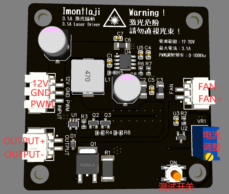
Semiconductor laser driver-supports 0-100K TTL modulation
Introduction: Laser constant current driver module that supports 0-100K TTL modulation, waveform rise time <2us, maximum output current 3.5A, input voltage 12-20V
QQ Group 730049694
This work follows the CC-BY-NC-SA 3.0 open source agreement. The forked project must indicate the original author and provide the original project link, and indicate whether any modifications have been made based on the original project. If you remix, If you convert or create based on this work and make it public, your project must also follow the CC-BY-NC-SA 3.0 open source license. Commercial use of this work and its derivative works is prohibited!
1. Product Introduction
This module supports 0-100K TTL modulation, drive waveform rise time <2us, maximum output current 3.5A, input voltage 12-20V.
2. Application scenarios
1. Laser engraving machine
2. Laser light source
3. Stage laser
3. Product overview
It can drive laser diodes of various wavelengths. The output port is designed with an ESD protection device to prevent static electricity from damaging the laser diode.
This module reduces the input power supply voltage to 5V, and then uses a voltage-controlled constant current source to drive the laser diode. The TTL/PWM signal is directly input into the op amp, so that the rise time of the module's output waveform is shorter, thereby increasing the modulation frequency.
The buck part uses MPS's synchronous buck chip MP8715, which has a conversion efficiency of about 95% and significantly reduces heat generation.
The voltage-controlled constant current part uses TL431 as the reference source, and the LM321 operational amplifier controls the N-MOSFET to ensure stable output current. At the same time, compared with the scheme of inputting TTL/PWM signal to the DC/DC chip, it can obtain a higher waveform rise speed.
4. Product parameters
4.1 Electrical parameters
1. Working voltage: 12V-20V
2. Maximum output current: 3.5A
3. PWM/TTL modulation frequency: 0-100Khz
4. Fan interface output voltage: 5V
4.2 Interface parameters
Power input interface: 12V , GND, PWM
laser output interface: OUTPUT+, OUTPUT-
Fan output interface: FAN+, FAN-
4.3 Mechanical parameters
PCB size: 60mm * 60mm Double-layer board design Single-sided layout
Screw hole position: M3 50mm * 50mm
5. Instructions for use
Connect 12V and GND are connected to the 12V-20V power supply (12V recommended), and PWM is connected to the PWM/TTL output port or switch. (The PWM port needs to be driven by push-pull or strong pull-up. When the voltage is >3V, the laser is turned on and when the voltage is <3V, the laser is turned off.)
Then connect the 5V fan to the FAN port, connect the red and black test leads of the multimeter to the OUTPUT port, turn on the power input, and press ON button, observe the multimeter current and adjust the potentiometer until the current meets the requirements of the laser diode, then connect the laser diode to test and light up.
6. Remarks
1. This module is pure hardware and can be controlled by simply inputting PWM/TTL signals.
2. Pure manual welding, the cost is estimated to be 6-12 yuan/Pcs (all materials, including PCB).
3. Jialichuang SMT library does not have MP8715 and XH2.54 terminals. If you choose SMT to place an order, you need to manually repair these components. In addition, the 100K potentiometer also needs to be hand-soldered by yourself. There is a component purchase link in the attachment.
4. The type of chip aluminum electrolytic capacitor needs to be selected according to the working voltage. When working at 12V, 16V 470UF is required. For operation at a voltage higher than this, 25V 330UF is required.
7. Demonstration
waveform rise time test chart

video uses 3.5A current, 10Khz modulation frequency, 0-100% duty cycle to drive Nichia NUBM08 450nm laser diode
64d9699b34e73476895f38e0fcb5756b.mp4
Laser driver-supports 0-100K TTL modulation.zip
BOM download
PCB_PCB_Laser Driver_2022-09-23.pdf
PCB_PCB_Laser Driver_2022-09-23.json
PCB_Laser Driver_2022-09-23.pcbdoc
Gerber_PCB_laser driver.zip
Schematic_Semiconductor Laser Driver-Supports 0-100K TTL modulation_2022-09-23.pdf
SCH_Semiconductor Laser Driver-Supports 0-100K TTL modulation_2022-09-23.json
SCH_Laser Driver_2022-09-23.schdoc
61668
Multimedia keypad ch552g
Introduction: Adapted from TheLight
Modified from https://oshwhub.com/TheLight/zi-ding-yi-jian-pan.
The low axis was changed to Kaihua axis seat, the light was removed, and it was changed to 0603 package.
The overall board was raised a bit using Lichuang Professional If you print the shell on the accessory
shell, you can also use it by just laying down the shell. The PCB and the lower shell are flush (1.6-thick board). For
firmware burning, please see the original article by TheLight guy.
You can do it yourself as a novice. If you have a guy, you can try wiring it yourself.
Shell, universal ec11 ec16.zip
BOM download
PCB_PCB_3jianpan_2022-09-23.pdf
PCB_PCB_3jianpan_2022-09-23.json
PCB_3jianpan_2022-09-23.pcbdoc
Gerber_PCB_3jianpan.zip
Schematic_Multimedia Keyboard ch552g_2022-09-23.pdf
SCH_Multimedia Keyboard ch552g_2022-09-23.json
Sheet_1_2022-09-23.schdoc
61669
electronic


 京公网安备 11010802033920号

 2SA1577T106QR


