Project Description:
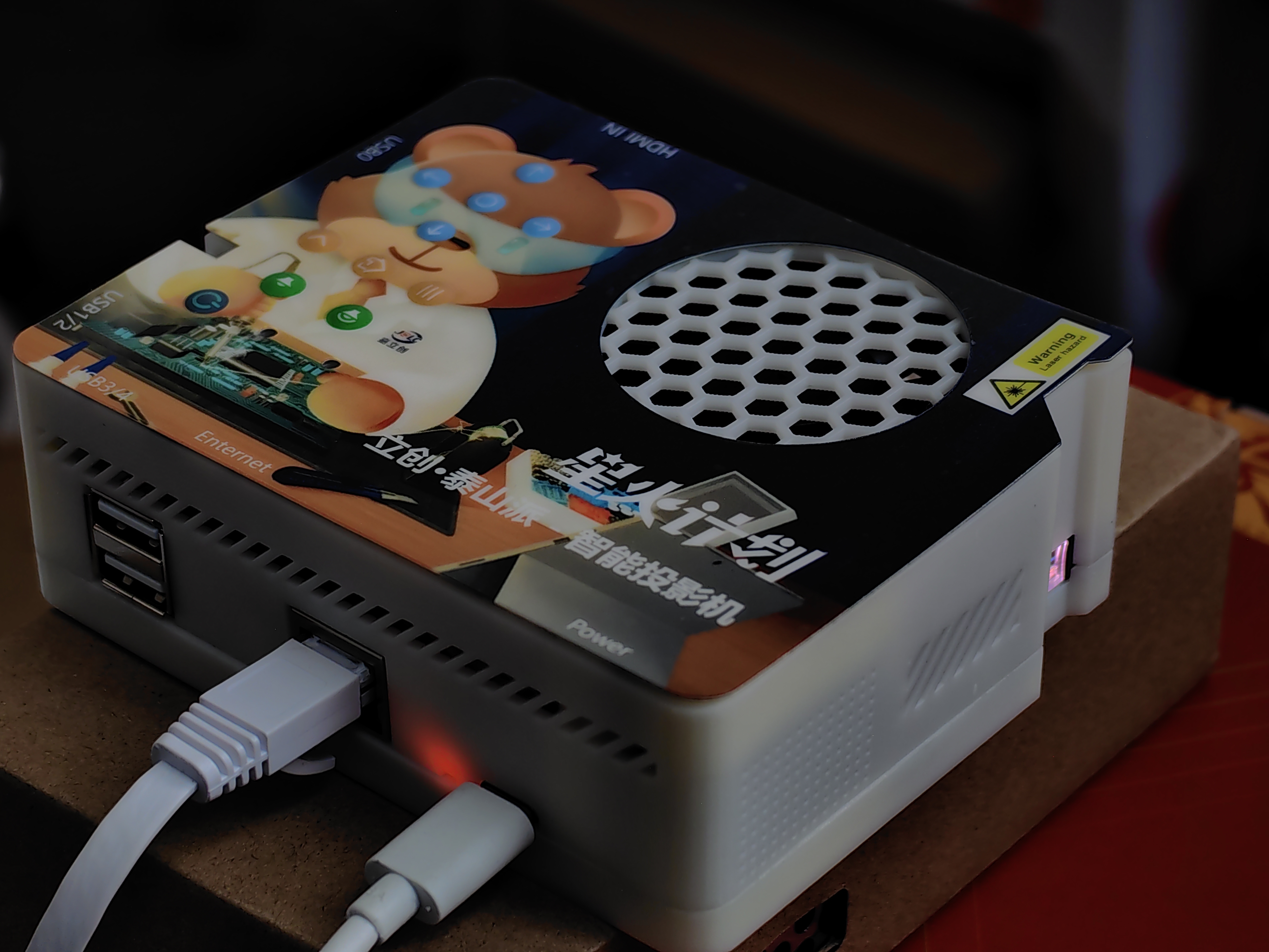
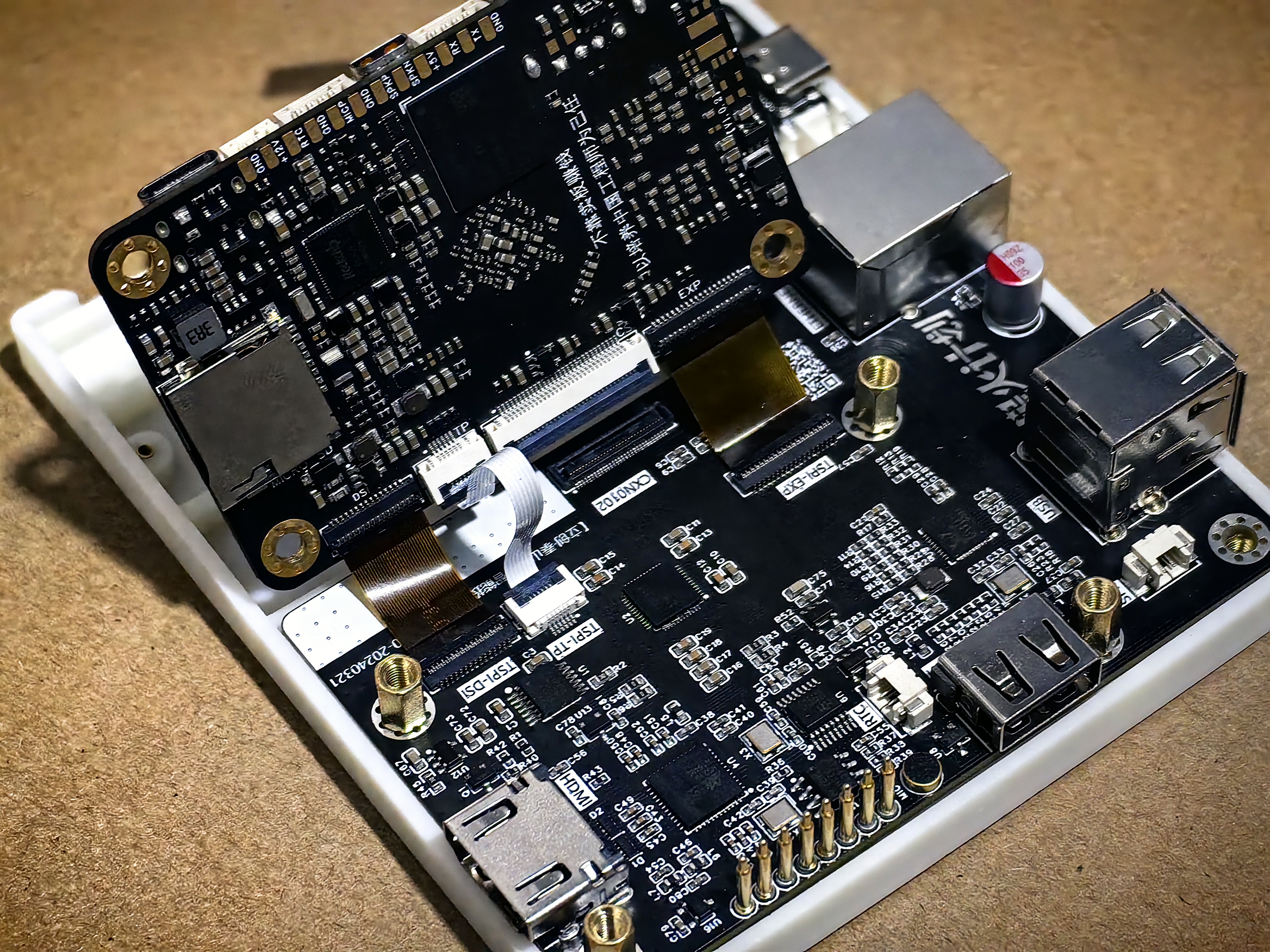
This project is based on the LCSC Taishanpai Development Board (hereinafter referred to as Taishanpai). It uses the ICN6211 bridging IC to drive the Sony laser galvanometer CXN0102 optical engine (hereinafter referred to as the optical engine), with a resolution of 1280×720. An Android TV system is created by modifying the official Android SDK repository.
Note that the laser galvanometer is not suitable for bumpy environments; therefore, it is not recommended for applications such as automotive mounting.
To protect your optical engine, do not directly unplug the power cord. Please press the power button to turn it off or put it into standby mode, and wait for the optical engine to turn off before unplugging the power cord!
More screenshots are available at the end of the article. This project is licensed under the CC-BY-NC-SA 4.0 (Creative Commons Attribution-NonCommercial-ShareAlike)
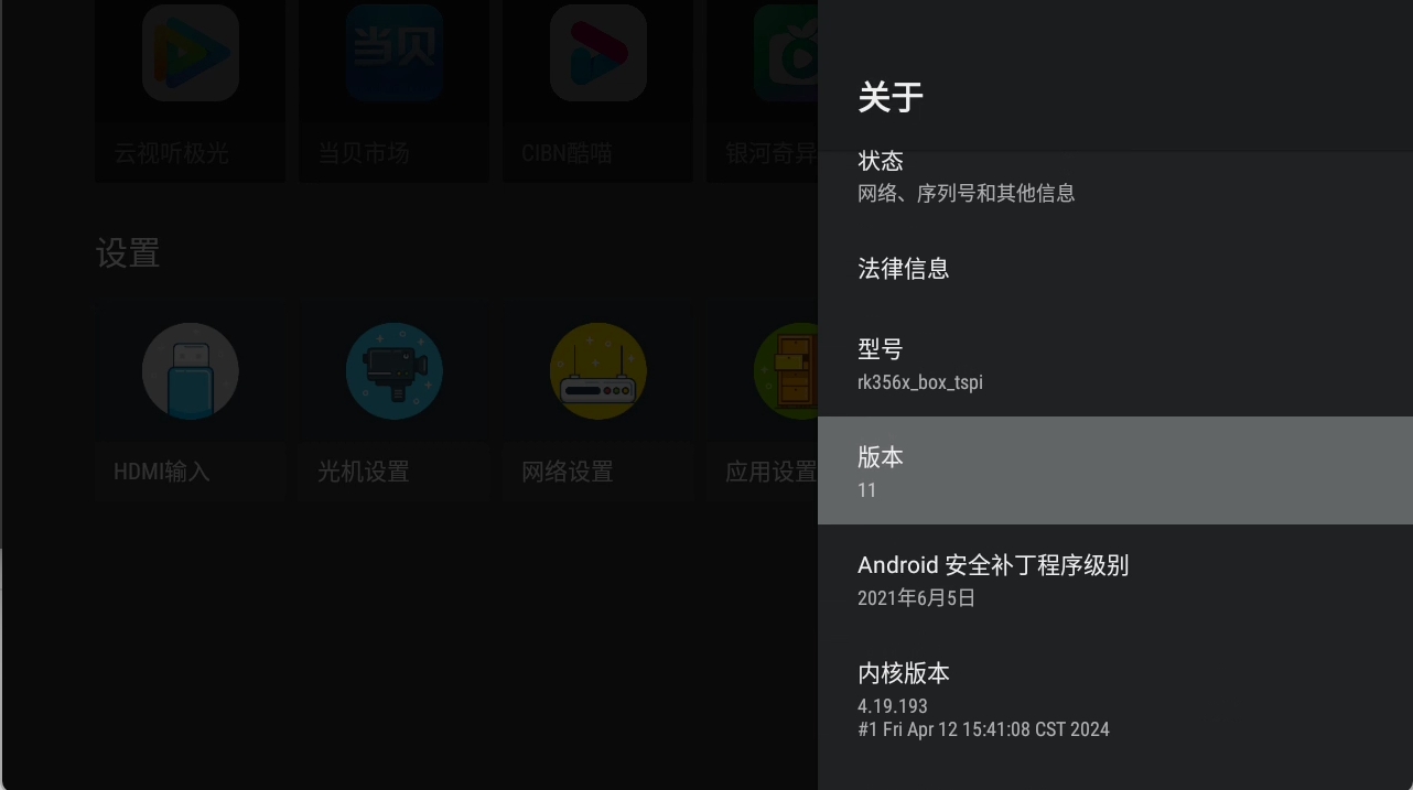
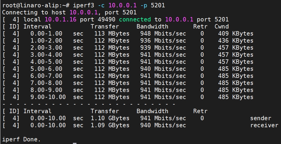
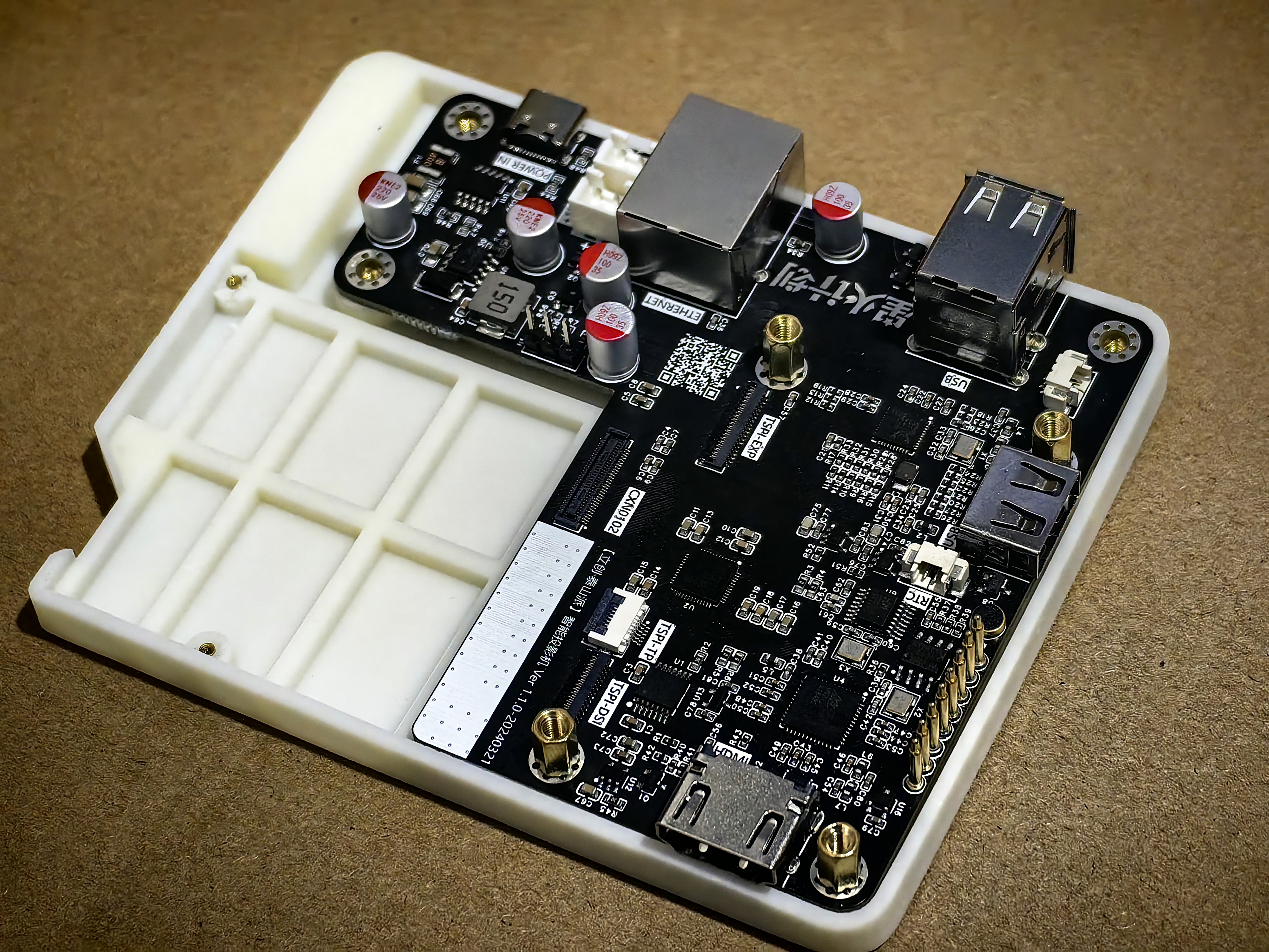
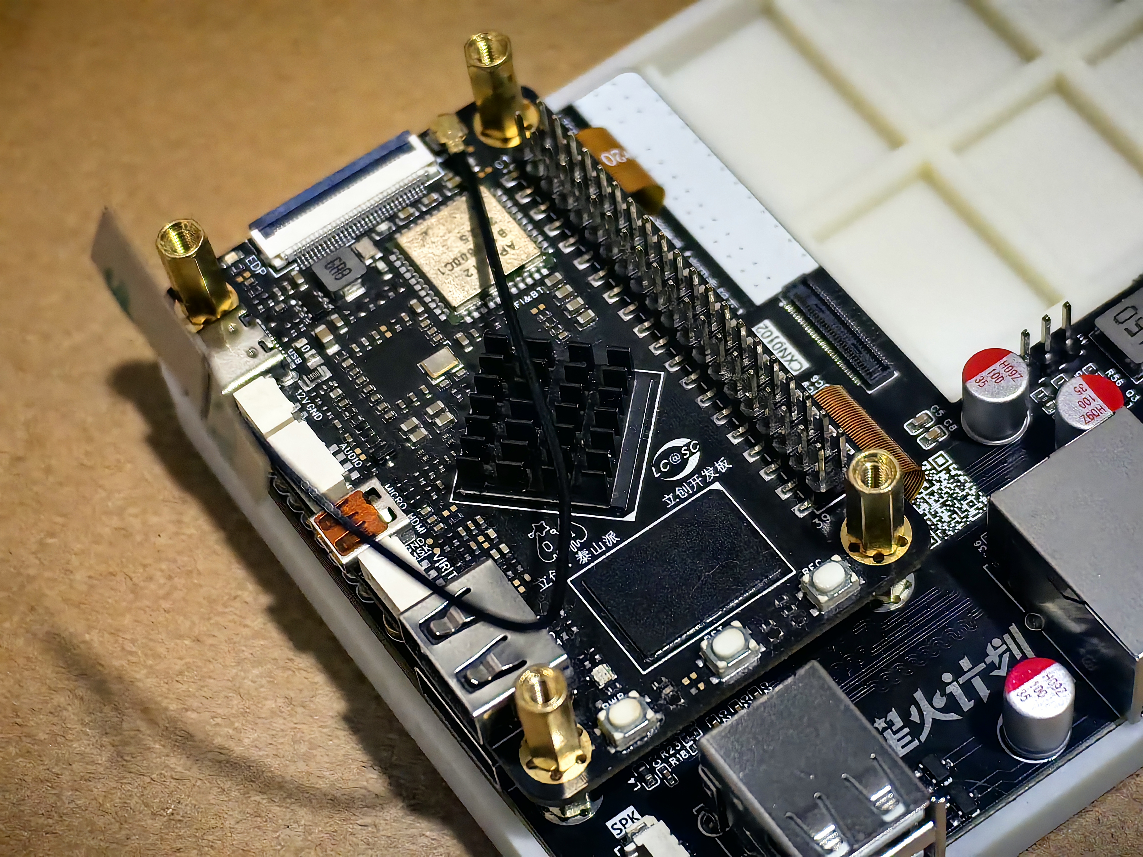
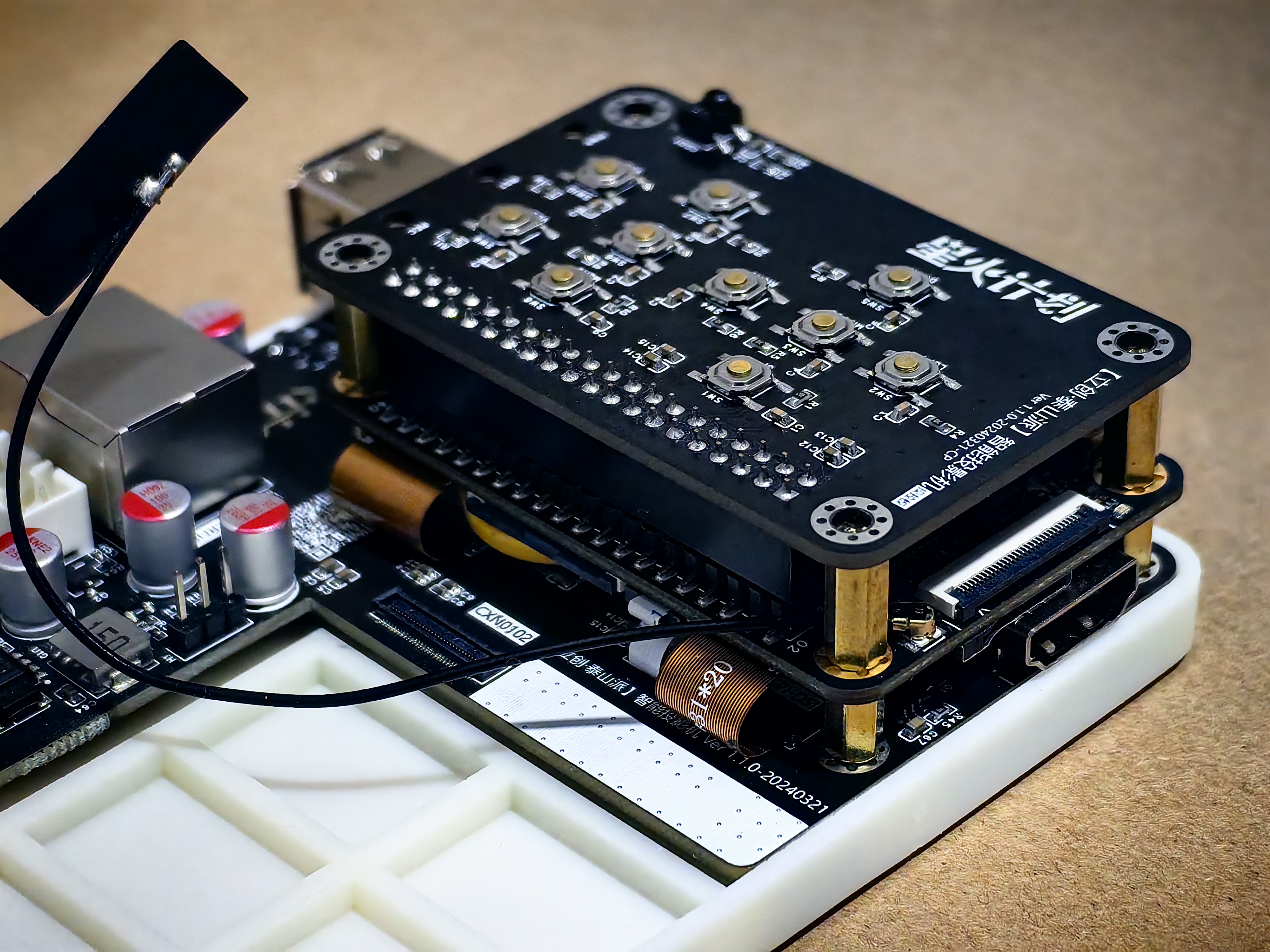
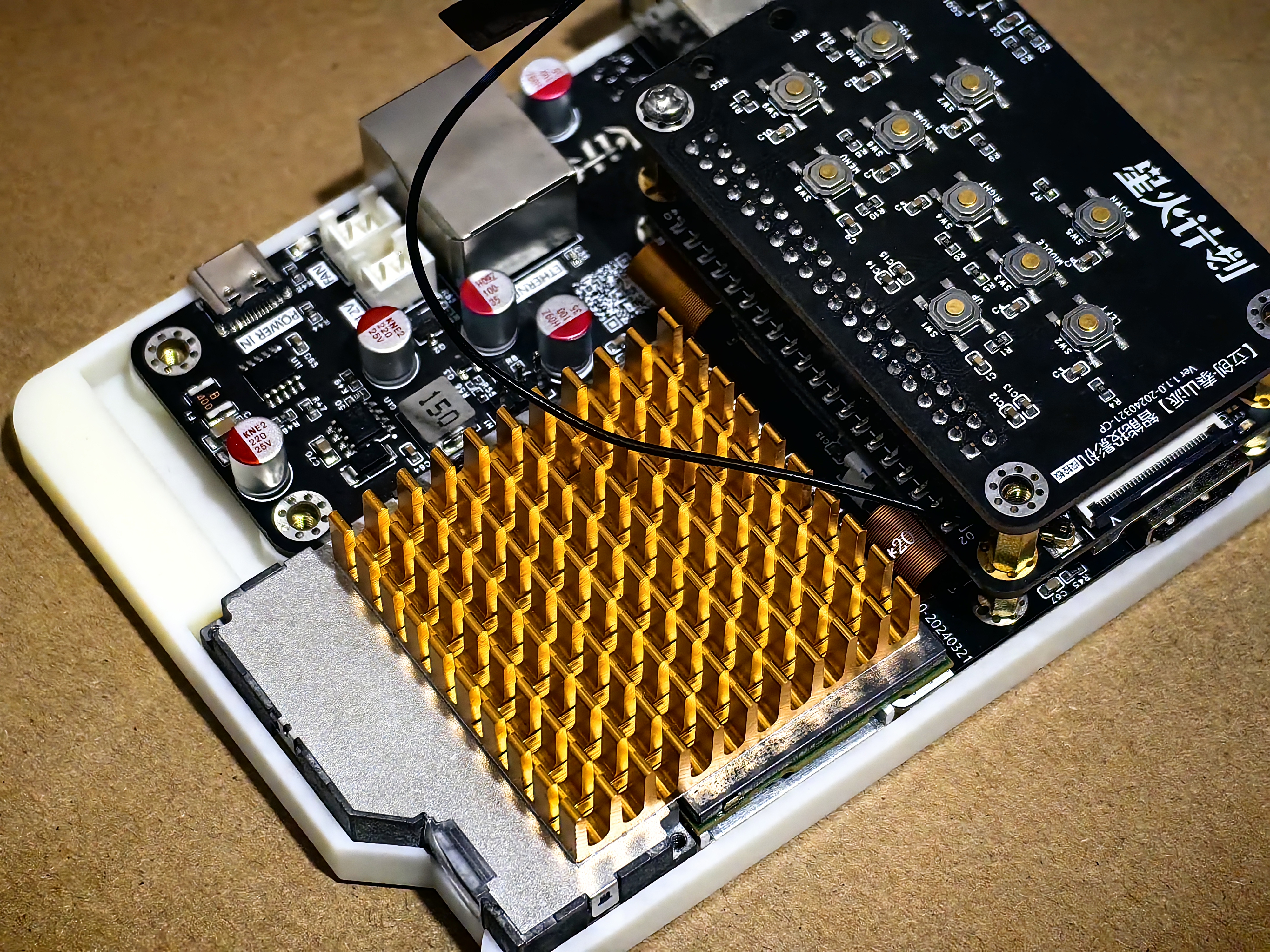
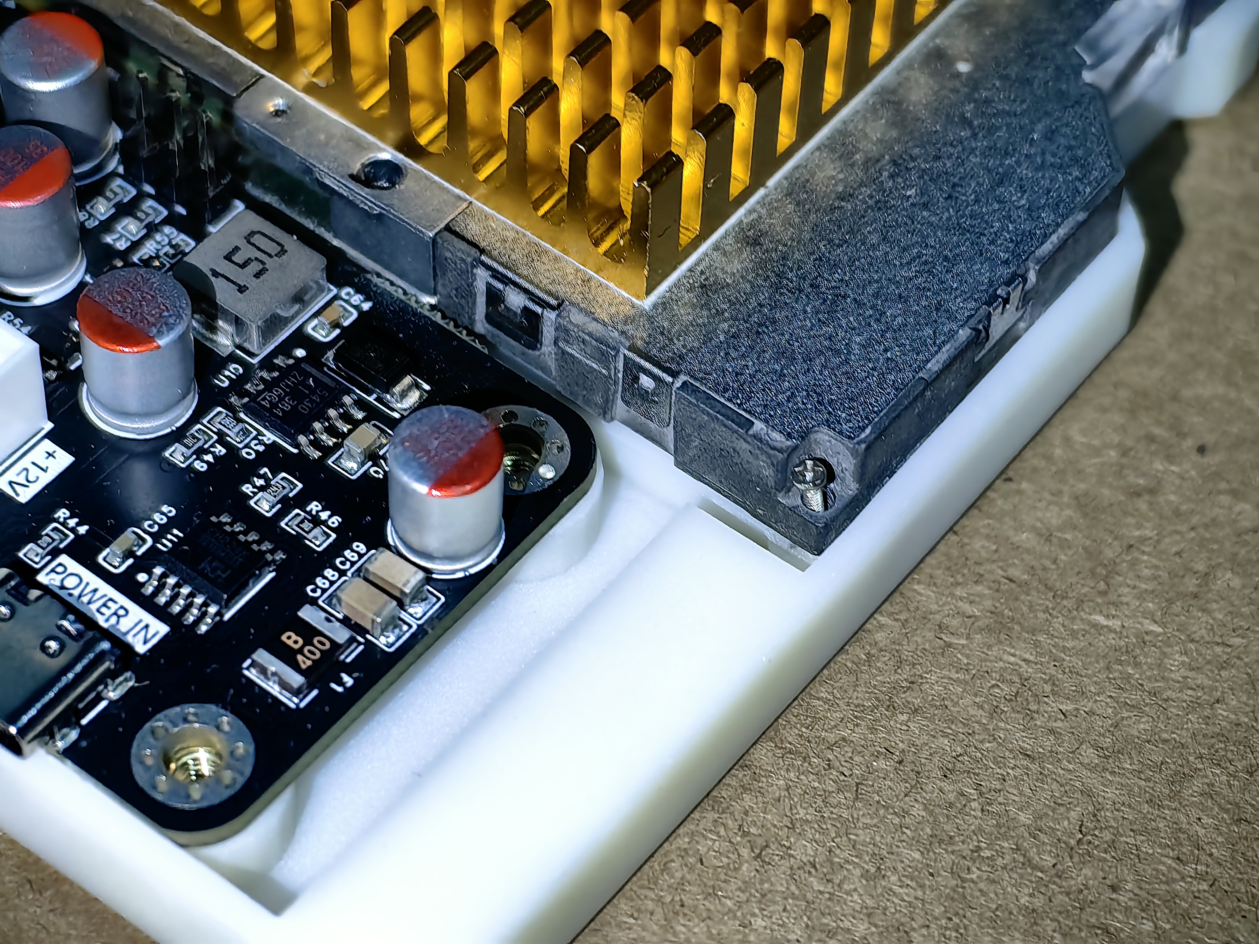
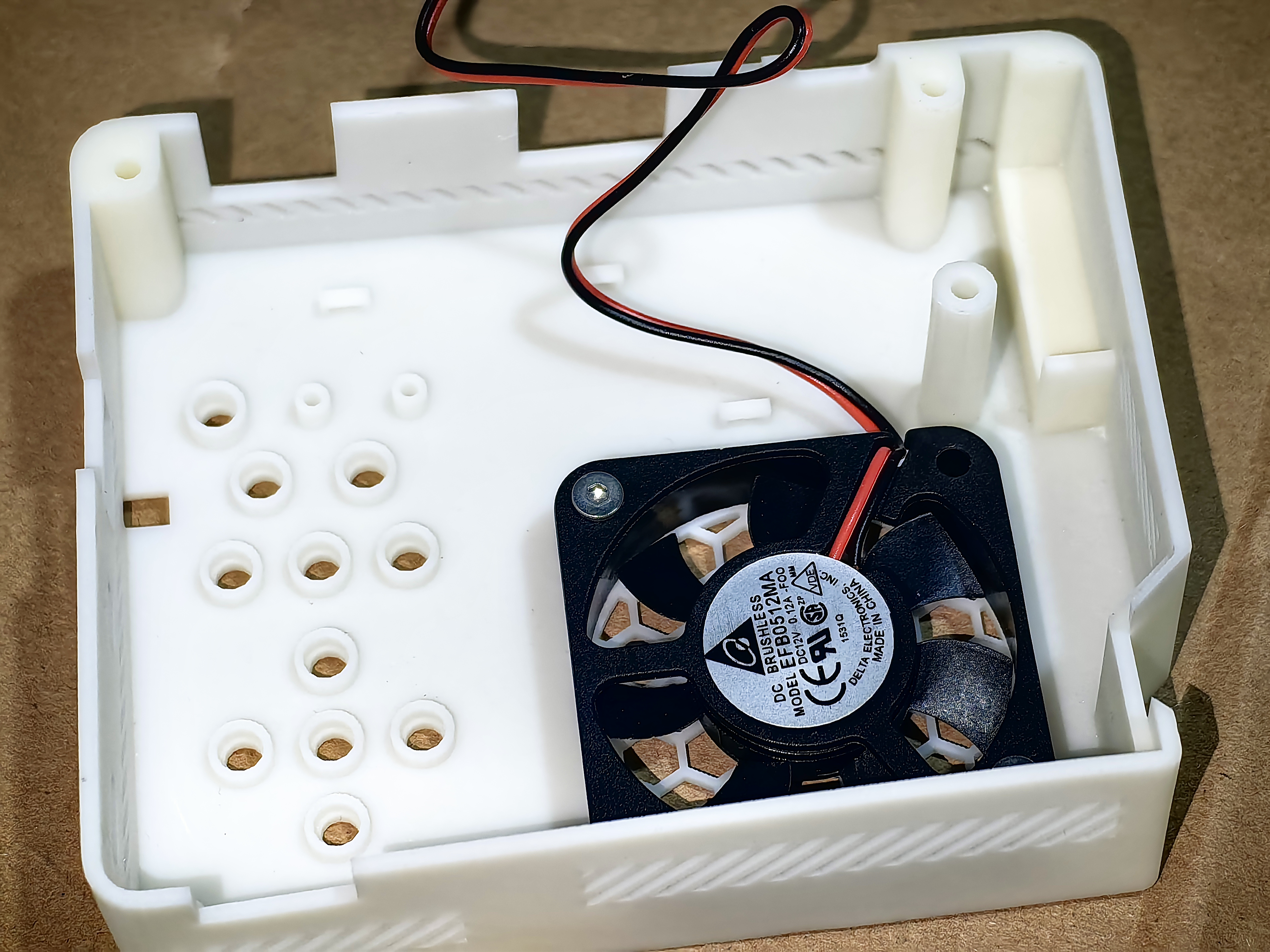
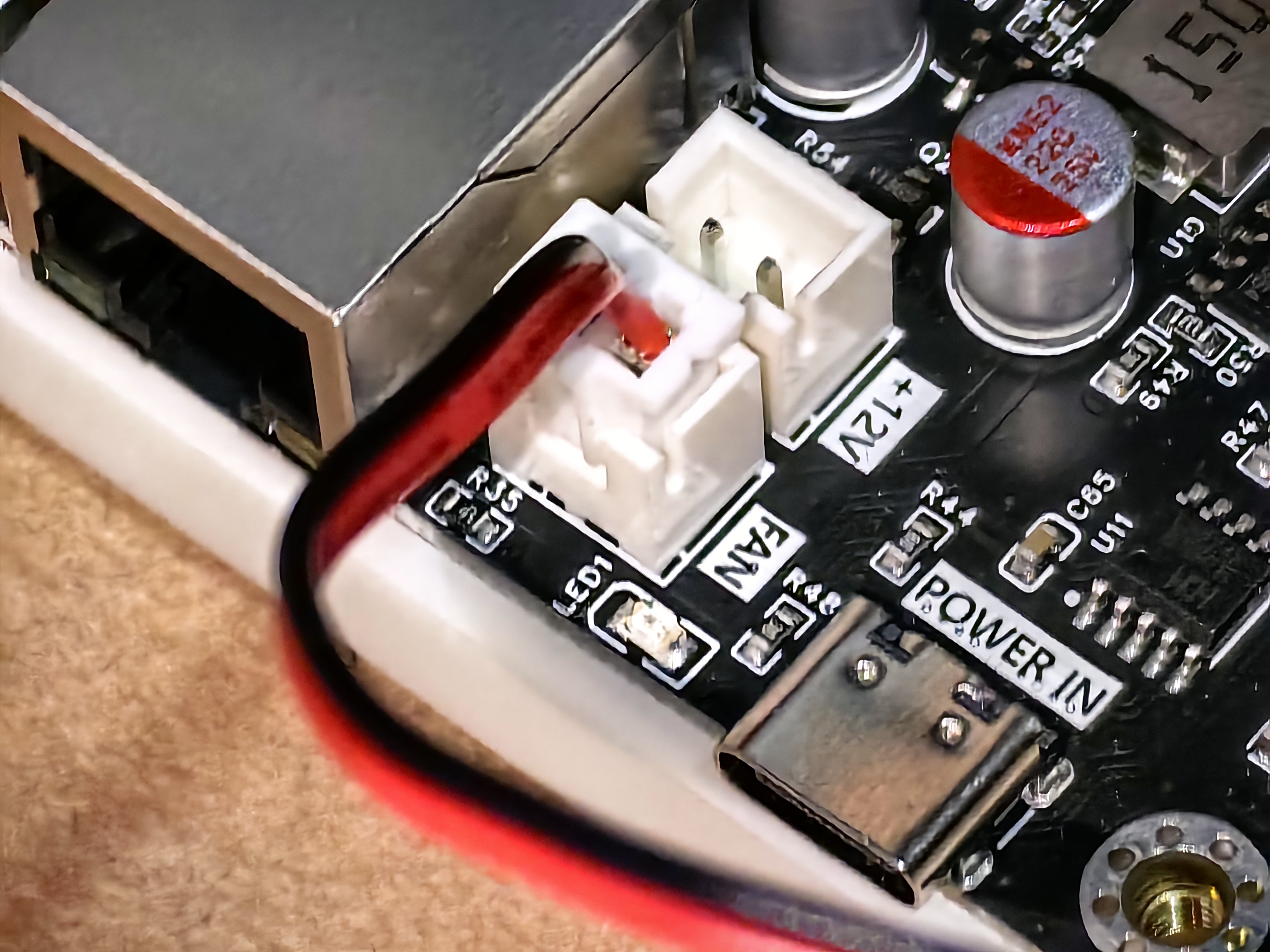
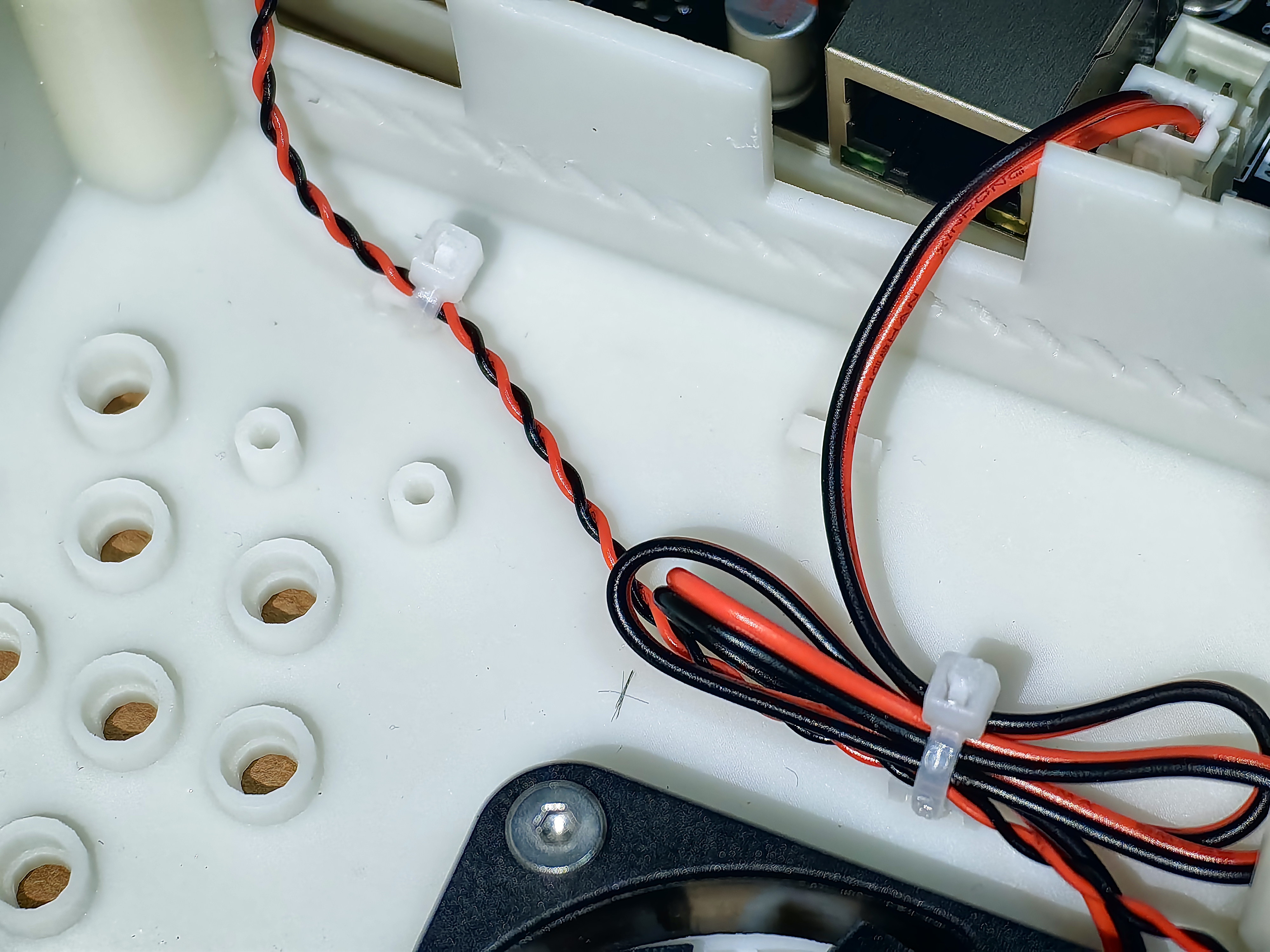
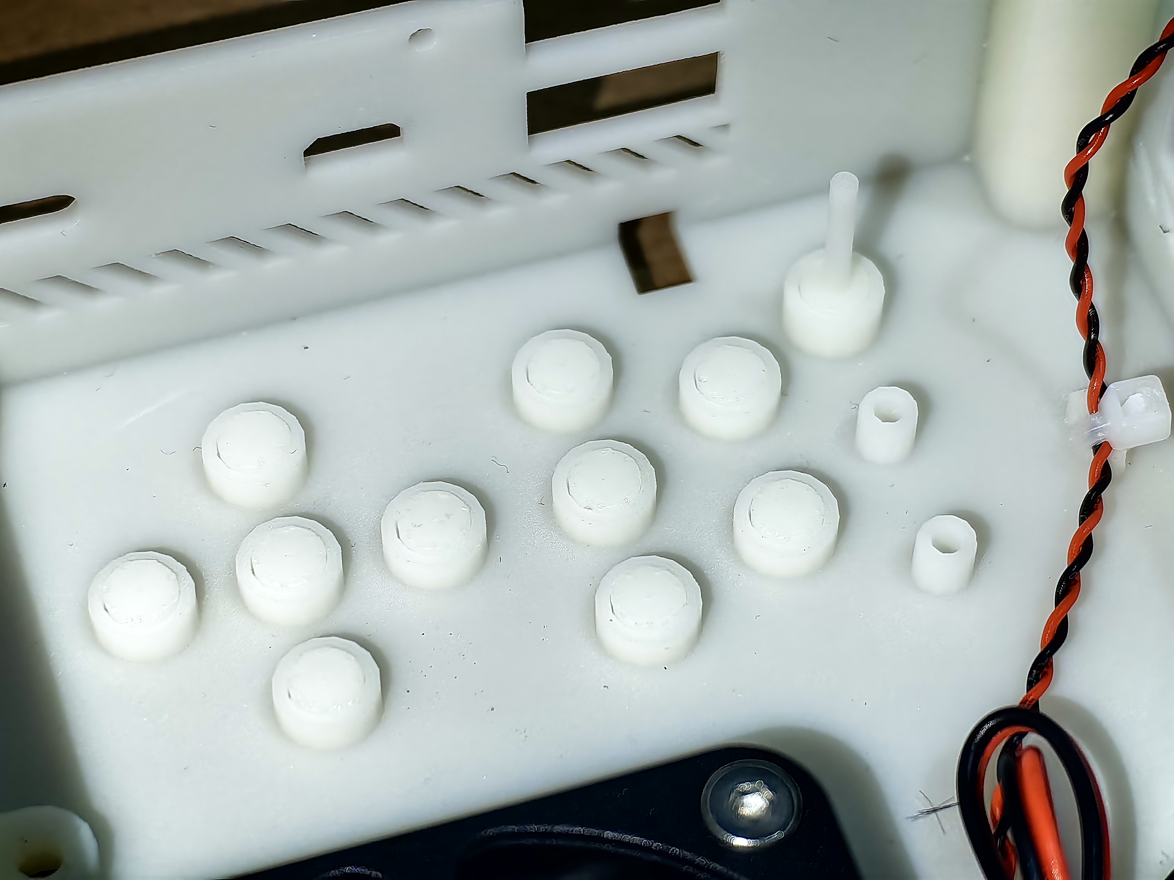
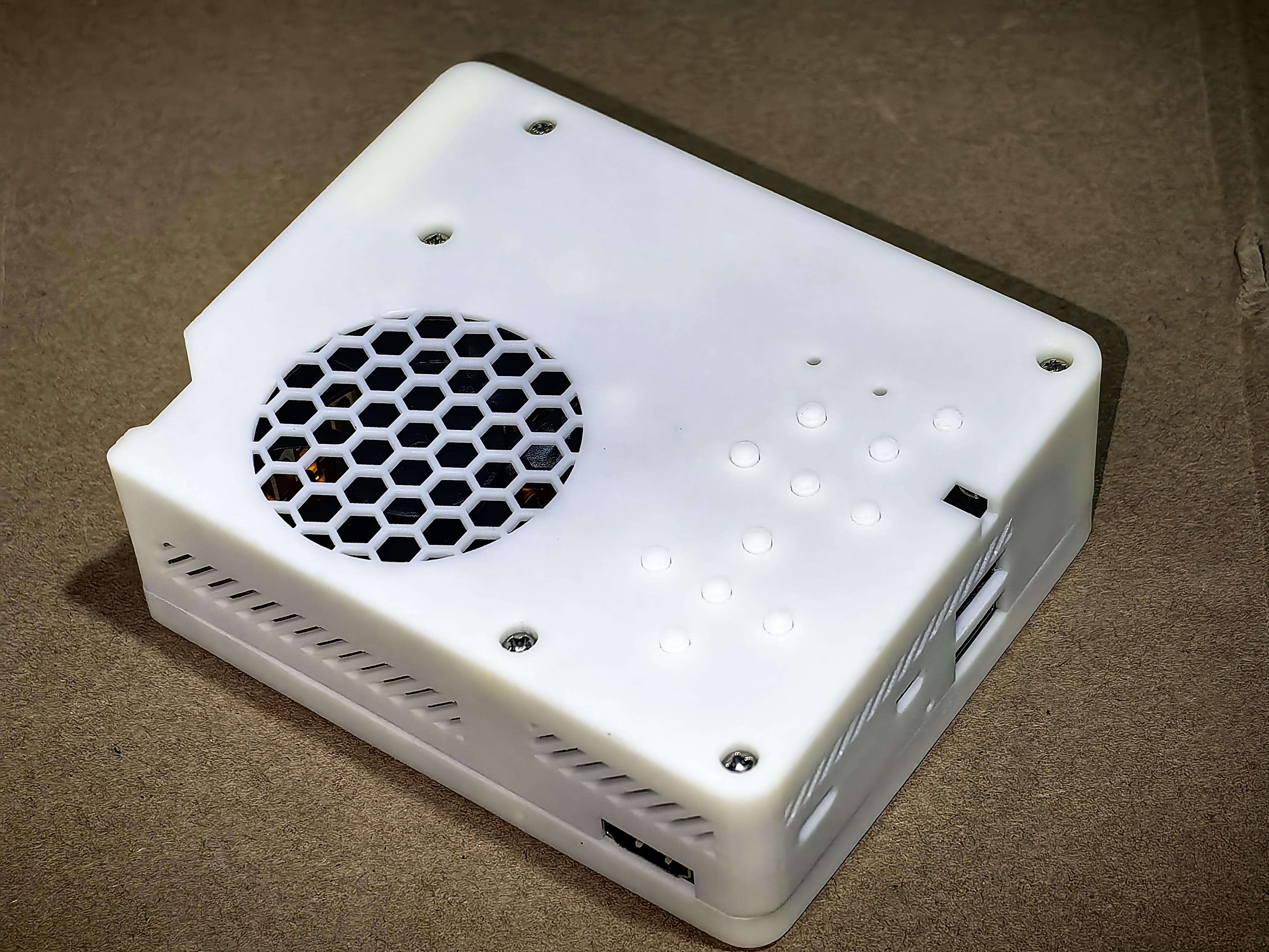
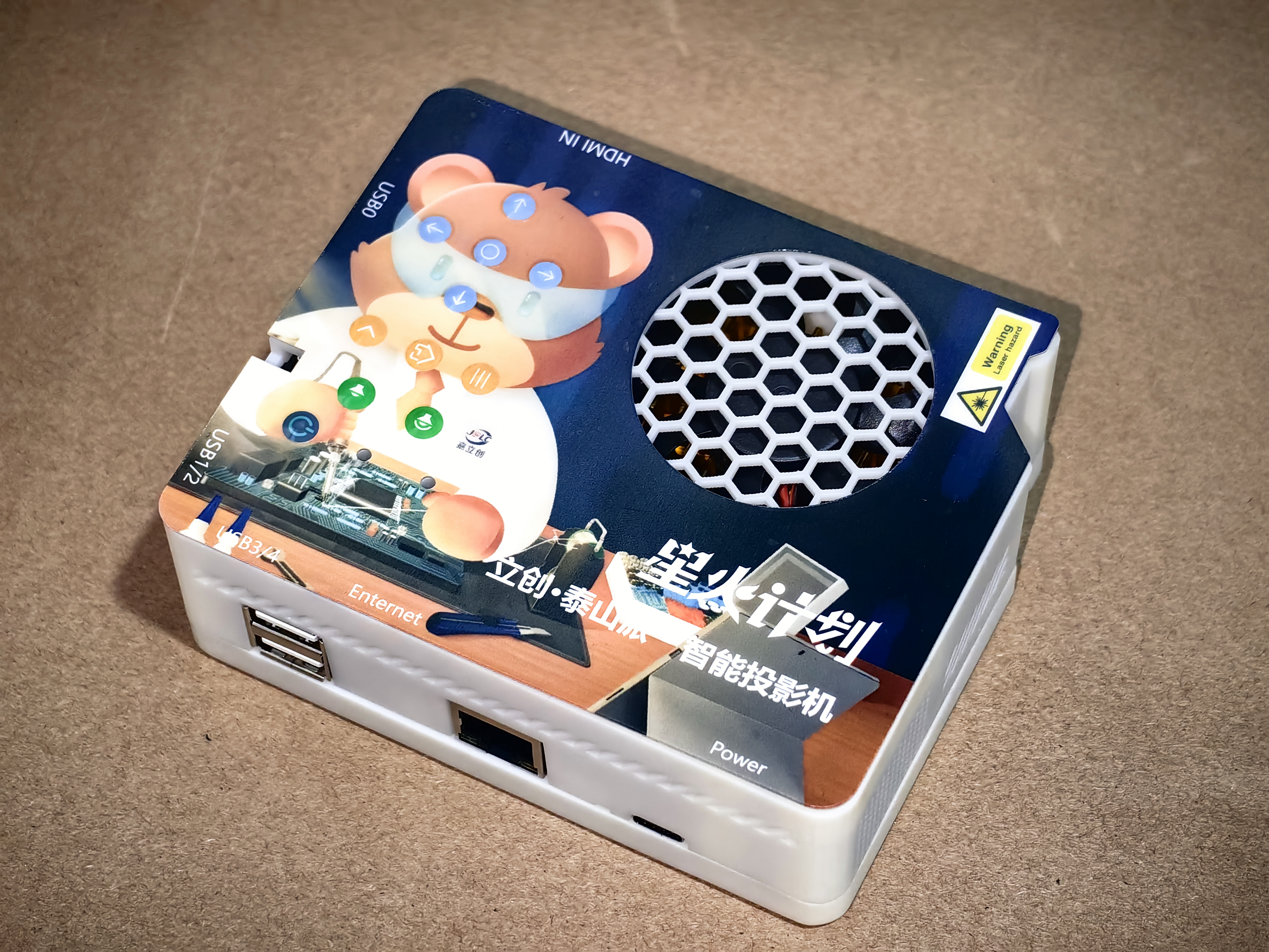
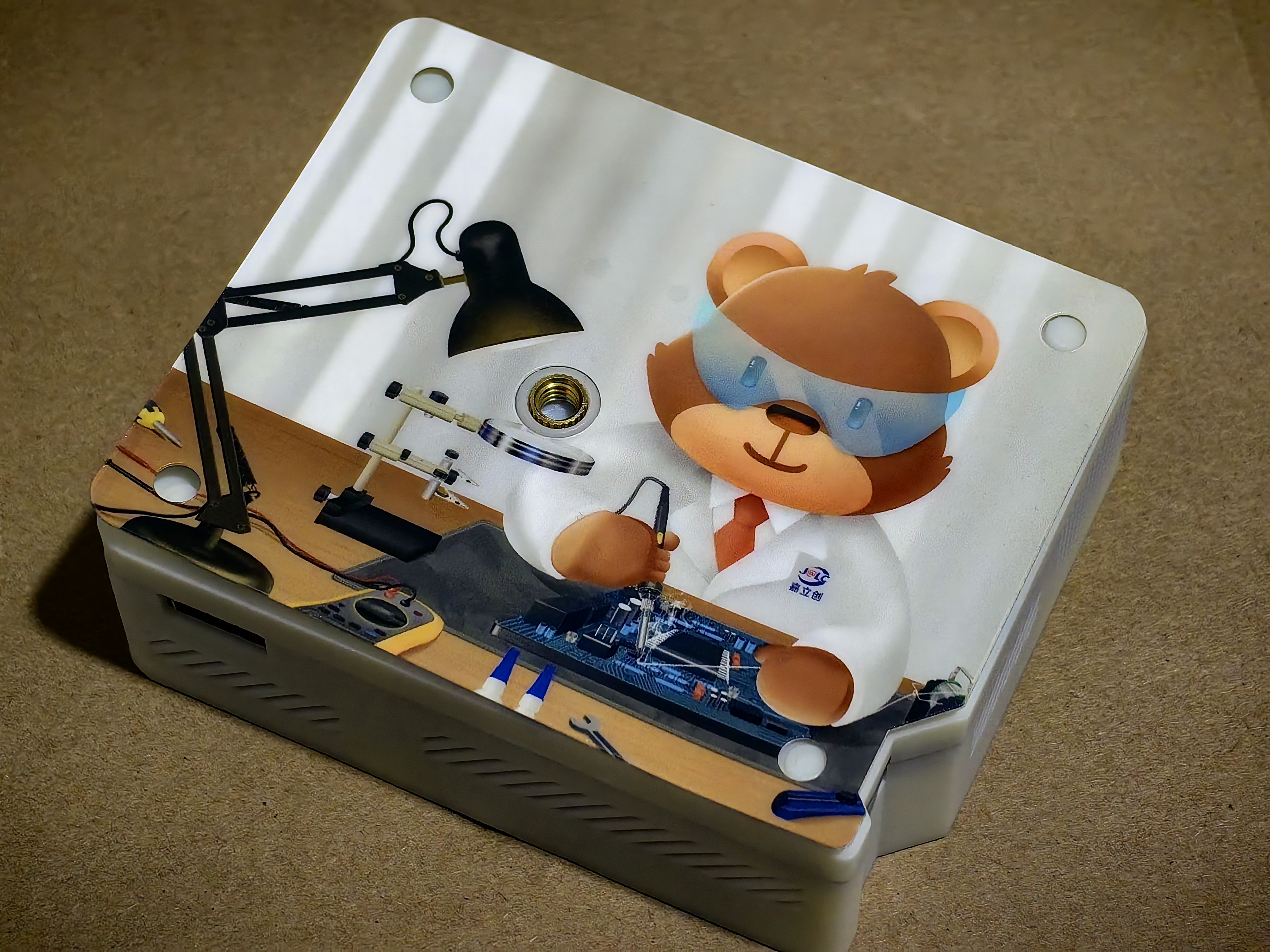
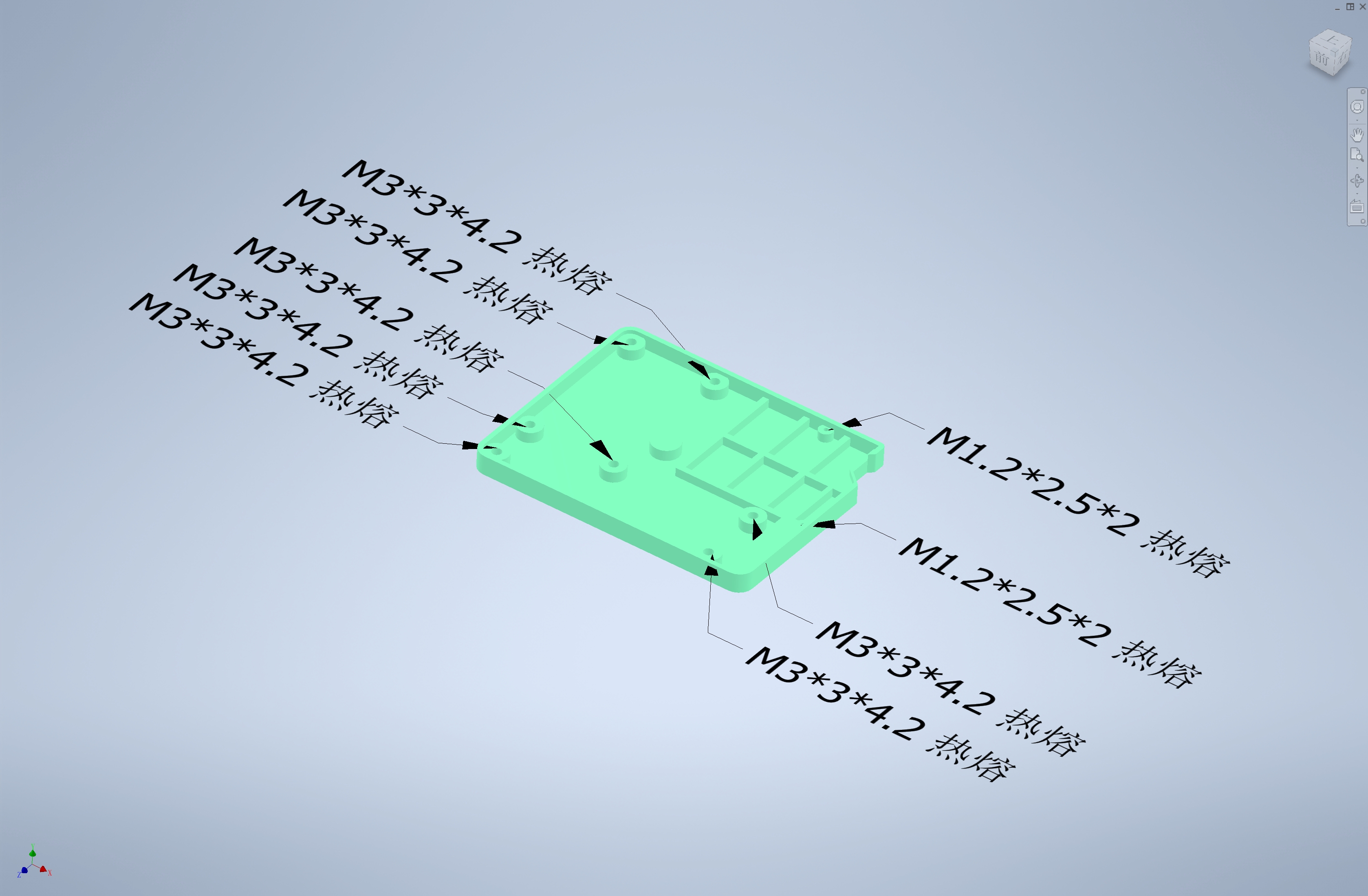
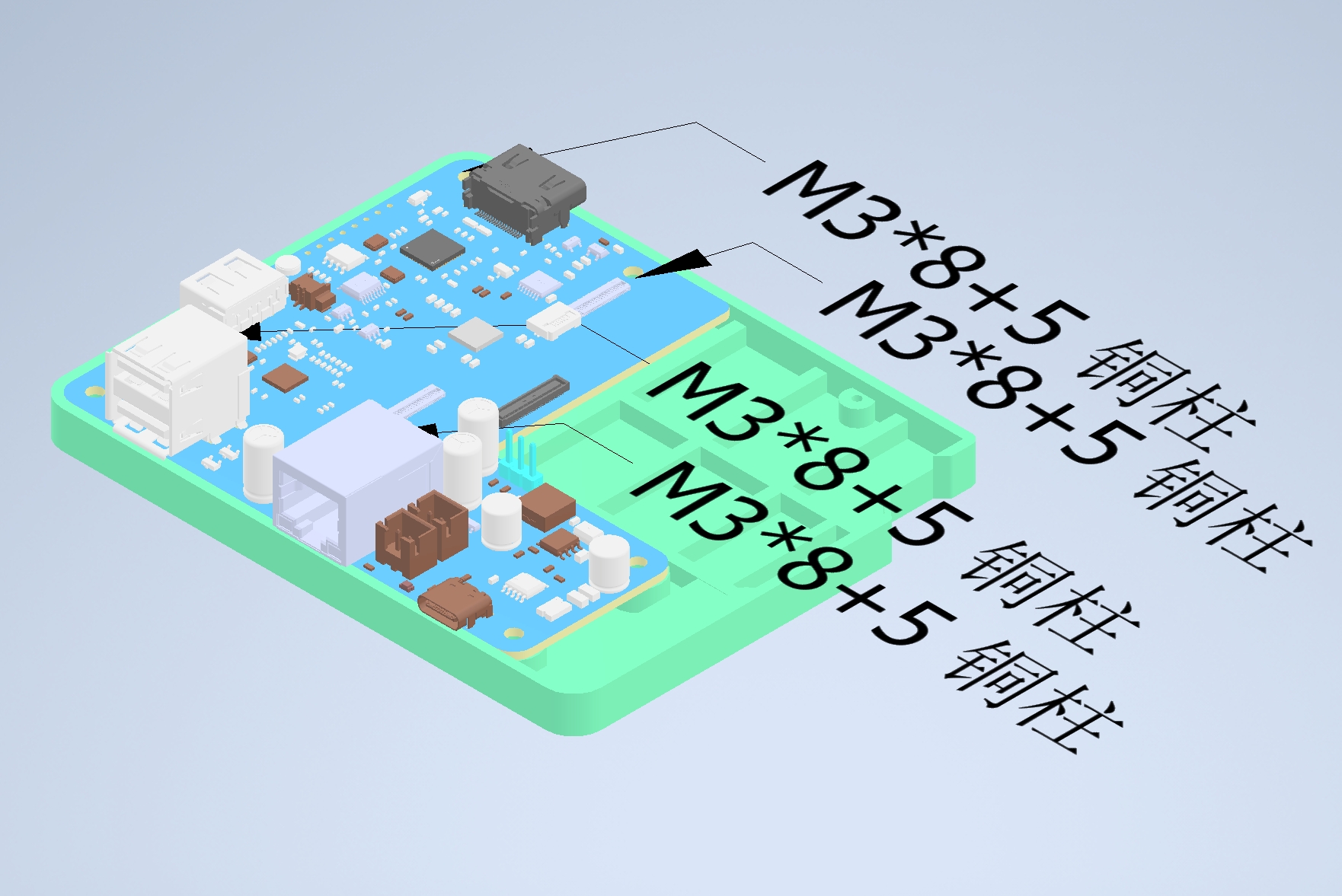
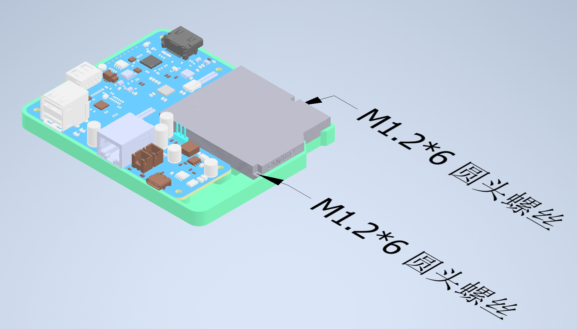
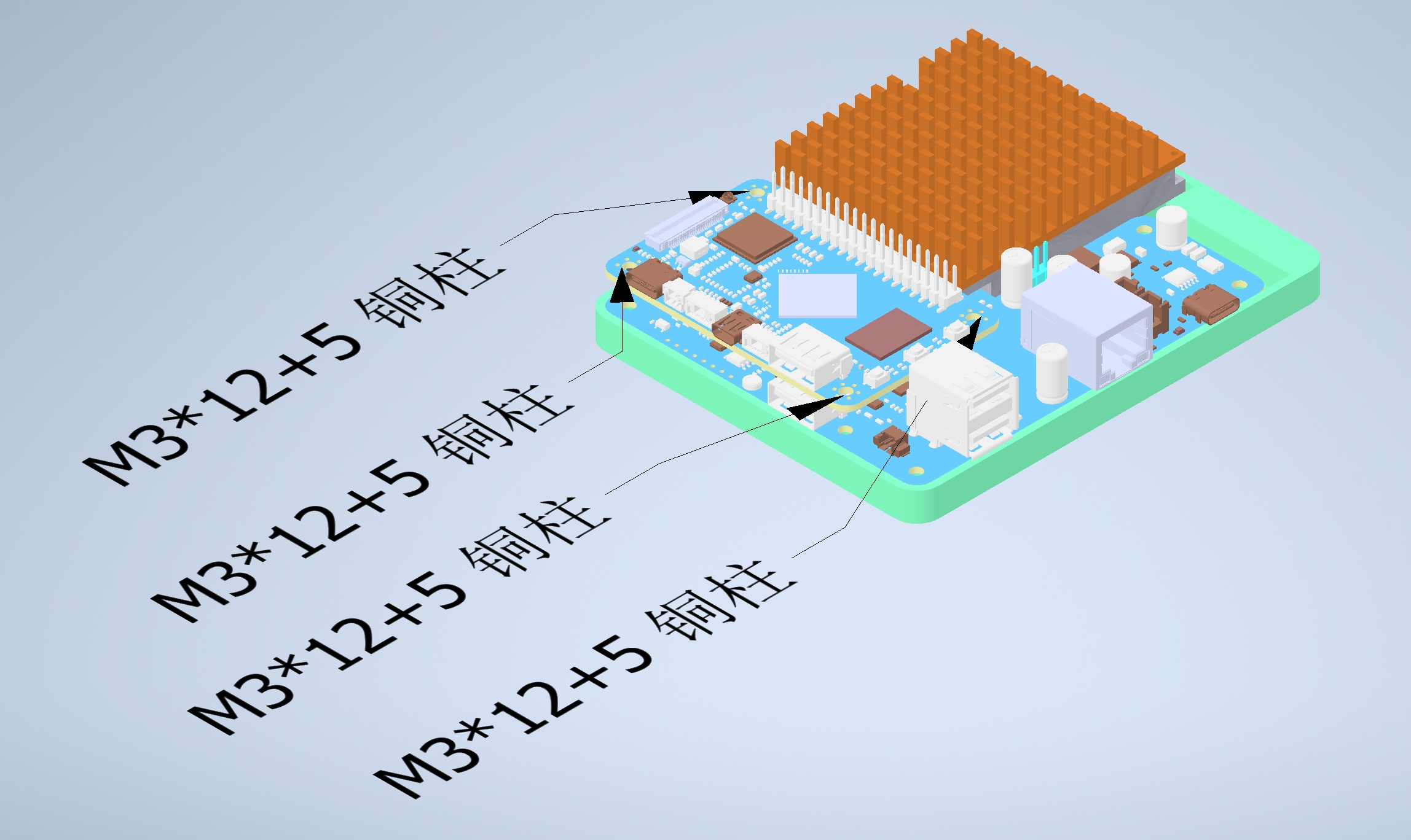
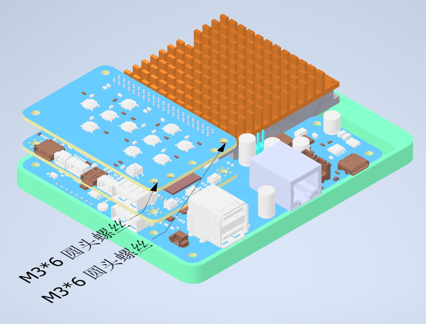
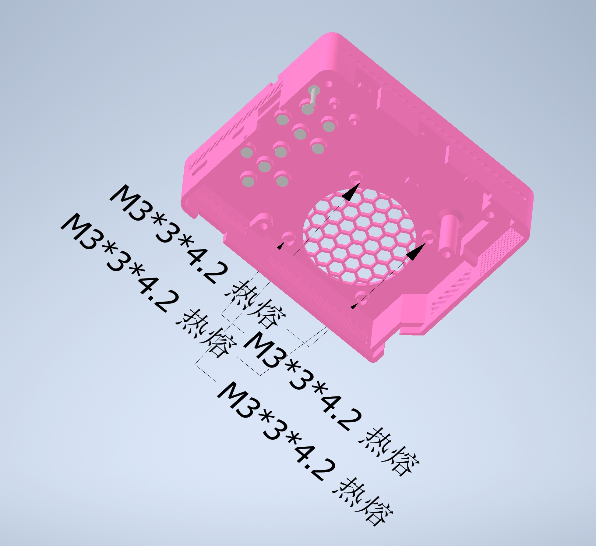
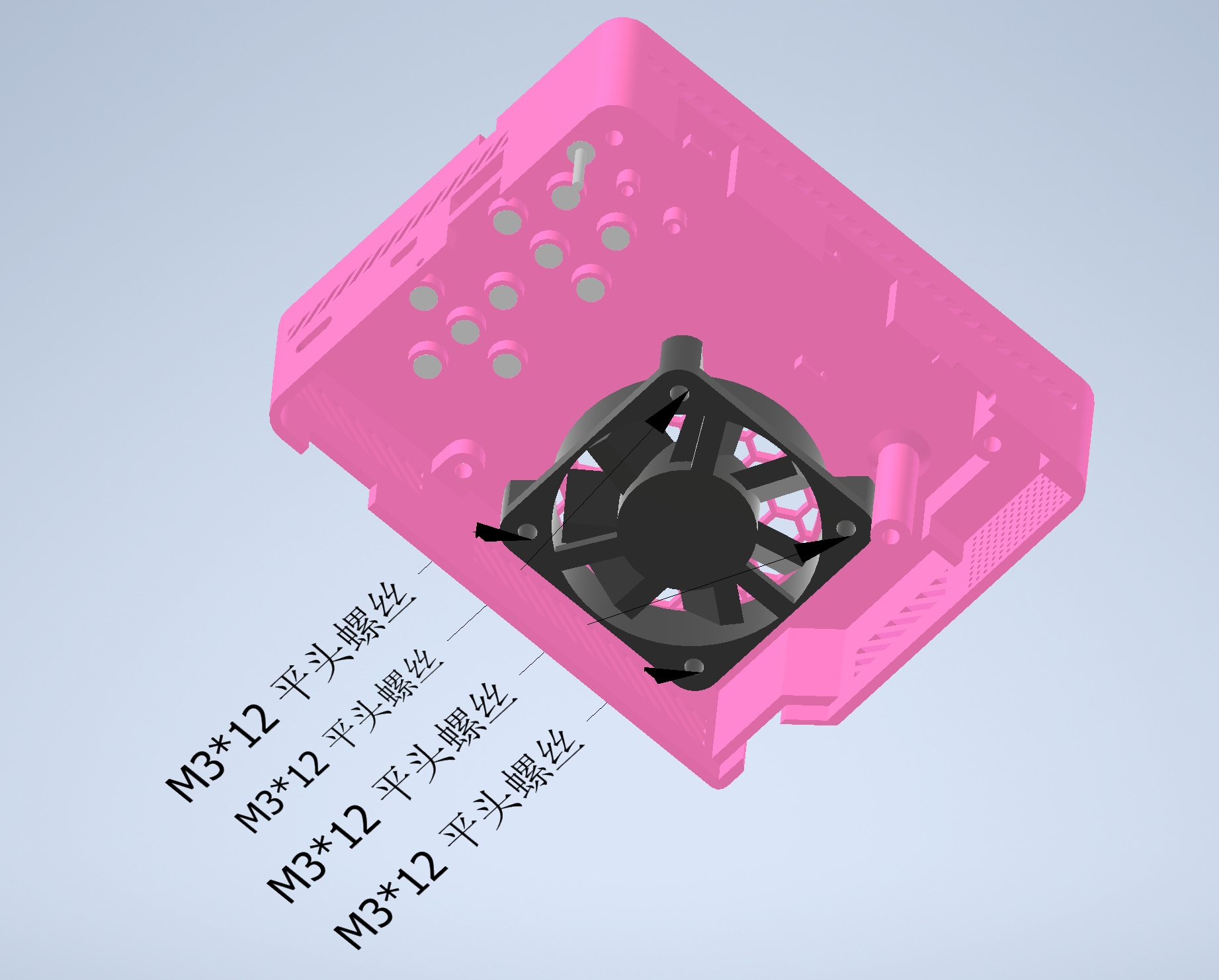
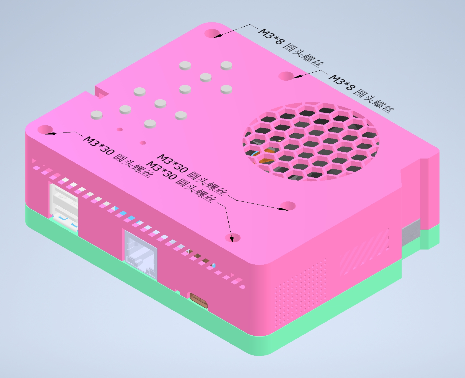
open -source license. It is shared as is without warranty, express or implied. Reading and understanding this project requires substantial knowledge of electronic hardware and software; please assess the risks involved. The author assumes no responsibility for any personal injury or property damage resulting from the use of this project. Exchange, replication, and derivative works are welcome, but unauthorized profiteering through replication is discouraged. If you disagree with the above information, please close this page immediately; if you agree, please continue reading. This project's firmware uses some commercial closed-source apps; please contact us to remove any infringing content. In case of discrepancies between this description and the Gitee hosting information provided later, the latest commit of the latter shall prevail. Project-related features: Android TV system, Android version 11; supports four USB inputs (USB flash drive, external hard drive, mouse, keyboard, air keyboard and mouse, etc.); supports TF card insertion (note that the TF card and HDMI interface are close together and may not be able to be used simultaneously); supports gigabit Ethernet access (throughput test under Debian can reach 940). (Mbits/sec); supports onboard Wi-Fi access; supports HDMI input (HDCP requires a separate key); supports infrared remote control, supporting key values for five common domestic remote controls: Baidu Movie Stick Box, Huawei Box, iQiyi Box, BesTV Box, and Dangbei Box; supports wireless screen casting (achieved via Dangbei screen casting), supporting protocols: DLNA, Miracast, Huawei Cast, etc.; supports mono speaker; supports RTC power-off retention time; supports automatic start/stop of the 12V cooling fan based on the optical engine temperature; a reserved 12V interface is provided for the Taishanpai cooling fan or power supply; supports 1/4-inch interface stands; the control panel has 10 buttons: up, down, left, right, OK, back, desktop, menu, volume up, and volume down. The power button (PWR) on the Taishanpai is led to the outer shell via a long button cap. The REC and RST buttons have openings large enough for a toothpick to pass through to prevent accidental activation; a customized system desktop supports application launch, HDMI input display, optical engine settings, etc. Project Attributes: This project is being publicly disclosed for the first time and is my original work. This project has not won any awards in other competitions. Unauthorized reproduction and commercial use are prohibited. The PCBA design principle uses the ICN6211 bridging chip for MIPI DSI to RGB signal conversion to drive the CXN0102 video signal; the MS2109 chip implements the HDMI capture card function to support HDMI input; the RTL8211F is used as the Gigabit Ethernet PHY chip; the CH334R is used as the USB 2.0 HUD to expand the USB interface; the CH213K ideal diode is used for reverse current protection of the USB interface; and the CH224K is used for PD protocol power reception to accept 12V power. The software SDK patch is based on the LCSC official repo version of the Android SDK: tspi_android_sdk_repo_20240202. The RKTvLauncher desktop in the original SDK has been replaced with the CTV desktop specifically developed for this project. SDK patch: git clone https://gitee.com/fengmoxi/tspi-cxn0102.git cd tspi-cxn0102 chmod a+x projector.sh ./projector.sh System compilation: cd u-boot && ./make.sh rk3566 && cd ../kernel && make ARCH=arm64 tspi_defconfig rk356x_evb.config android-11.config && make ARCH=arm64 tspi-rk3566-user-v10.img -j16 && cd .. && source build/envsetup.sh && lunch rk356x_box_tspi-userdebug && make -j16 && ./mkimage.sh && ./build.sh -u Precautions: To protect your optical engine, do not unplug the power cord directly. Please press the power button to turn it off or put it into standby mode first, and wait for the optical engine to turn off before unplugging the power cord! Assembly process: See the fastener assembly diagram below for the dimensions of the thermosetting nuts and screws! The images in this process may be from an older version of the casing; please refer to the actual product! After inserting the thermosetting nut into the bottom cover, use an 8mm long copper pillar to fix the main control board; use 0.3mm pitch 31-pin co-directional FPCs, 0.3mm pitch 39-pin co-directional FPCs, and 0.5mm pitch 6-pin co-directional FPCs to connect the main control board and the Taishanpai; install the RTC battery; use a 12mm long copper pillar to fix the Taishanpai; insert the control board into the Taishanpai; screw in the M3*6 screws at the positions shown in the diagram on the control board ; connect the optical engine to the main control board via the BTB interface; use two M1.2*6 screws to fix the optical engine; connect the speaker to the main control board; fix the cooling fan to the top cover; connect the fan to the main control board; use cable ties to fix the speaker and fan leads to the top cover; insert 10 short button caps and 1 long button cap into the corresponding mounting positions on the top cover, note that the long button cap is used for the PWR position; close the top cover and tighten the fixing screws; attach the front and back panels, and you're done! Offers three panel styles: minimalist, anime-style, and bear-themed (a tribute to JLCPCB's custom mousepad). Project progress (Changelog).


This project requires long-term maintenance. We welcome like-minded individuals to collaborate and offer valuable suggestions.
2024-05-05
Fixed the issue of lost image quality settings after restarting.
Fixed the issue of lost ceiling settings after restarting.
Updated pre-installed software
. Replaced C68 and C69 capacitors to prevent safety hazards caused by insufficient 12V withstand voltage.
2024-04-29
Adjusted the outer casing wall thickness from 2mm to 1.5mm to prevent difficulties in installing the optical engine due to FDM technology.
Removed the bottom protrusion of the bottom cover to reduce 3D printing difficulty.
Enhanced the fault tolerance of the thermoforming nut implantation
. Adjusted the speaker mounting surface position to resolve interference with a solid capacitor.
Added an optical engine support sheet and moved the cooling fan forward to strengthen the connection between the optical engine and the main control board.
Opened the TF card slot
and updated the panel openings.
2024-04-13
Casing and panel verification.
2024-04-09
HDMI IN display uses the UVC protocol for direct display instead of CameraX's PreviewView.
The Launcher grants USB permissions by default, eliminating pop-up windows.
If HDMI is already plugged in at startup, it will directly open HDMI. The IN display screen
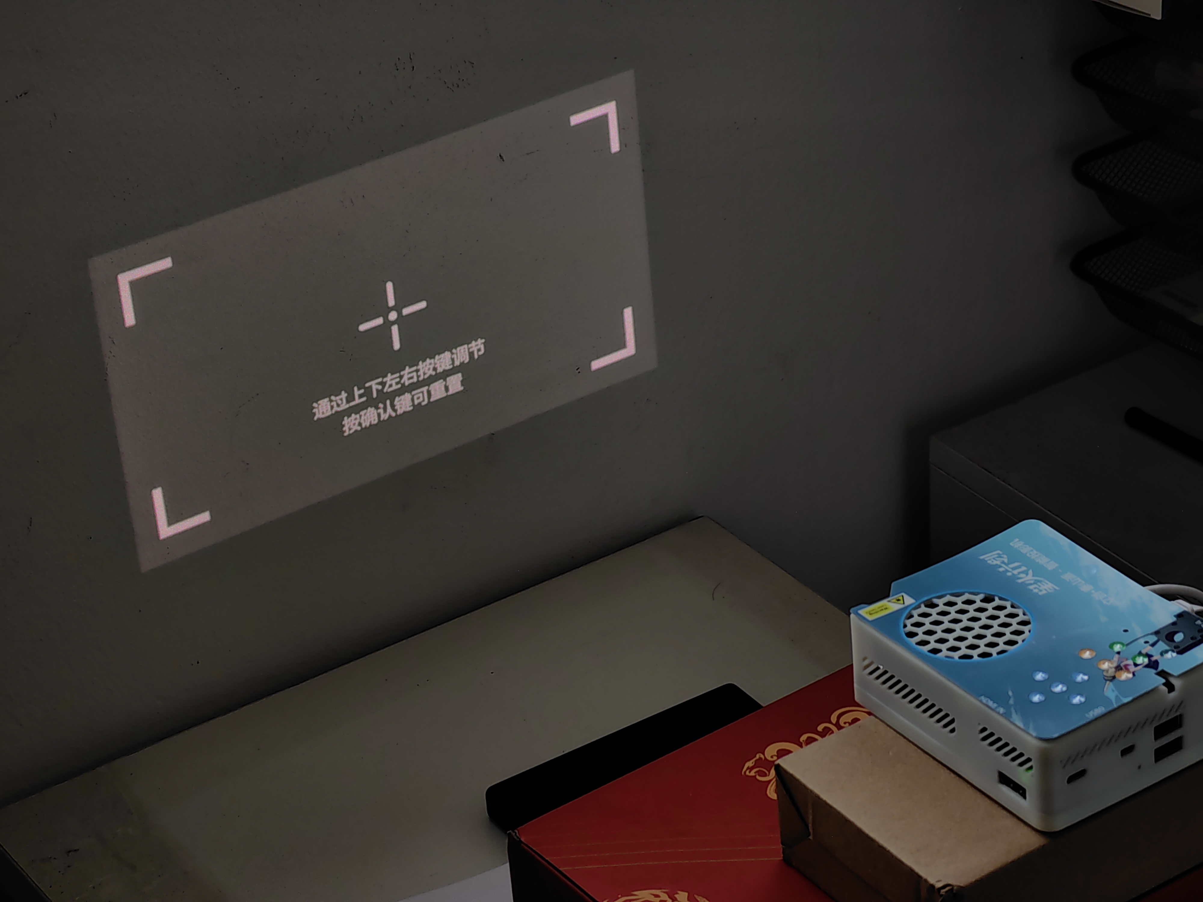
supports optical engine axis and phase adjustment.
(2024-04-06)
Automatic fan start/stop based on optical engine temperature (auto-on at 45°C, auto-off at 35°C).
Fixed the issue of the infrared remote control not responding to the HOME button.
(2024-04-05)
Completed the outer casing design
; completed the top and north side design.
(2024-04-02 )
Completed main control board v1.1.0 verification; completed
control board v1.1.0 verification.
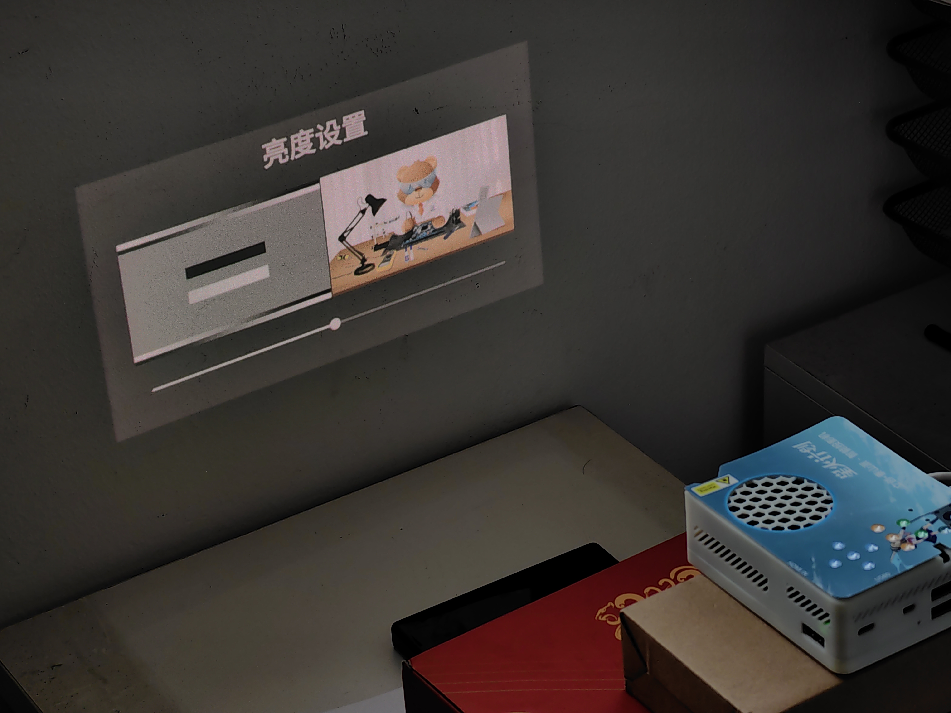
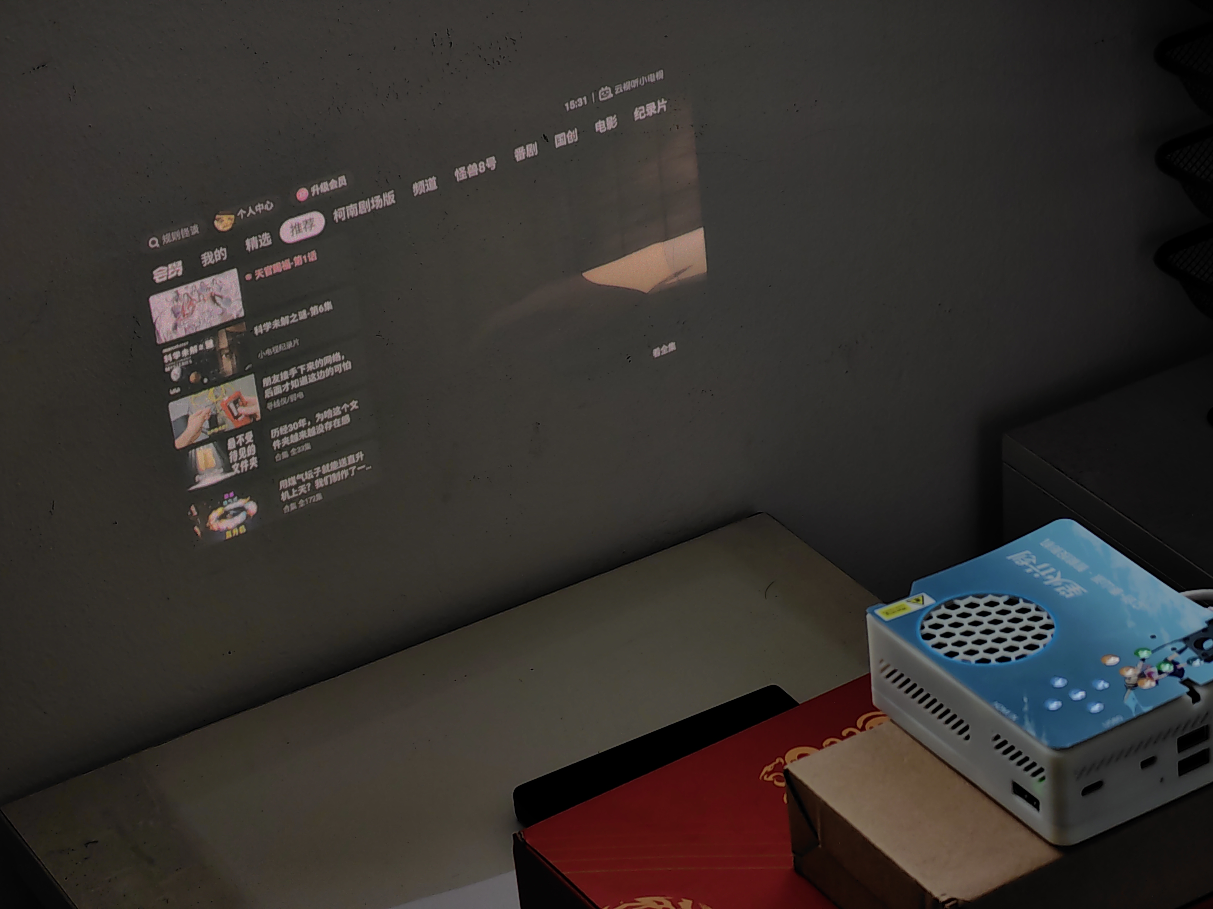
Completed custom desktop APP development (supports optical engine parameter adjustment, HDMI input display, and HDMI plug/unplug response). (
2024-03-22
)
Completed the first layout revision (v1.1.0) for both the main control board and control board.
2024-03-12
Optimized HDMI capture card related circuits.
2024-03-07
Completed MIPI to RGB related initialization code.
Completed CXN0102 power-on, power-off, output on, and output off.
2024-03-04
Completed main control board verification .
Completed control board verification .
2024-02-21 Completed
initial layout of the main control board.
Completed initial layout of the control board.
Material
Description: The following recommended purchase channels are for reference only. I also purchased materials through these channels, and I do not receive any commission or rebate. For pre-sales and after-sales issues, please negotiate with the corresponding merchants. Item
Number,
Model
Number, Reference Number ,
Description:
Recommended Purchase Channel
1
CXN0102
-
Sony optical engine, resolution 1280×720, commonly found in Daling Xiaobao robot disassembly, Magic Mirror,
etc. Search for Xiaobao robot optical engine on Xianyu.
2
MS2109
U4
The HDMI to USB chip requires programming in the EEPROM (part number U8). Recommended purchase channels are: 1) buying a complete chip kit with programming service, or 2) directly disassembling the chip. I have personally purchased from both. [Links provided:
https://m.tb.cn/h.5ttrr5tBDHldpIx?tk=PgyGWkBJooh] [Links provided:
https://m.tb.cn/h.5AWu7xssHUIkFIy?tk=ngNpWKUuKp7 ]
3.
24C16
U5
(see MS2109 instructions)
4.
ICN6211
U2
RGB to MIPI chip, out of stock on LCSC Mall: [Links provided
: https://m.tb.cn/h.5ttHAts4gWU3eXm?tk=o8jaWkBssbR ]
5.
CH213K
U6/U7/U8
0.5A low dropout current limiting diode chip, not available on LCSC Mall
: https://m.tb.cn/h.5Gh2jpi0CUMa9i2?tk=TwVRWkBGywG
6.
Cooling fan
-
50*50*10 [12V], CXN0102 cooling fan, not necessary:
https://m.tb.cn/h.5B9BUkCeAEXgkNm?tk=Kuh2WKUwwL3
7.
Heatsink
-
45*45*10 with adhesive backing, CXN0102 heatsink, necessary!
If a cooling fan is not installed, a larger size and thickness can be used:
https://m.tb.cn/h.5zjbUYSW3MN9YdG?tk=YUfwWKUwd5n
8
Speakers
-
2030 housing, installed in the reserved position on the right side of the main control board
: https://m.tb.cn/h.5A7zpKciF3zMhrd?tk=pdv1WK9PGgf
9
RTC Battery
-
CR2032 B wiring sequence :
https://m.tb.cn/h.gZjCNx1mEw4ek6T?tk=8aUtWJPf5BG
10
39-pin ribbon cable
-
0.3mm pitch, 39-pin in the same direction:
https://m.tb.cn/h.ga5sStpNX8yU9AV?tk=IAICWJPelFF
11
31-pin ribbon cable
-
0.3mm pitch 31-pin co-directional
https://m.tb.cn/h.5AGUPNnS3sHFoyR?tk=KNx8WJPVt2W
12
6-pin ribbon cable
-
0.5mm pitch 6-pin co-directional
https://m.tb.cn/h.gaI6VUzcpUkeXOo?tk=EC9RWJPVdeR
13
3D printed top cover
- STL file
attached
-
14
3D printed bottom cover - STL file attached - 15 3D printed short button caps - STL file attached, for 10 buttons on the
control panel, 10 need to be printed - 16 3D printed long button caps - STL file attached, for Taishanpai onboard PWR buttons - Fastener list number type size quantity recommended purchase channel 1 Hot melt copper nut M1.2*2.5*2 2 https://m.tb.cn/h.5AecjZTscUgBwE5?tk=0RQUWKg1TYF 2. Hot melt copper nut M3*3*4.2 11 https://m.tb.cn/h.5Ae23zj2jWMR4cB?tk=5bFtWKgXl5B 3. Hot melt copper nut 1/4*6*8 1 https://m.tb.cn/h.5BPfntPv4sAEYfh?tk=vRMQWKg2MMV 4. Flat head screw M3*12 4 https://m.tb.cn/h.5BP51S5Po4Scomq?tk=Uec7WKgXbgW 5. Single-head hexagonal copper post M3*8+6 4 https://m.tb.cn/h.5zaxeKBh4UIOuIQ?tk=kD5AWKgXpQ5 6 Single-head hexagonal copper post M3*12+6 4 https://m.tb.cn/h.5AeX5M5636MGRgX?tk=6wc0WKg2AUy 7 Round head screw M1.2*6 2 https://m.tb.cn/h.5Ae2Sv6fPK1Bs7l?tk=v3nKWKg2C3V 8 Round head screw M3*6 2 https://m.tb.cn/h.5BPUHP0yzUOR38J?tk=cDfgWKg2rss 9 Round head screw M3*8 2 https://m.tb.cn/h.5zay0kverOrU4nP?tk=VWt6WKgXIjb 10 round head screws M3*30 3 https://m.tb.cn/h.5zay7SfLXJuvE9o?tk=9H5nWKgdNsK Fastener assembly diagram Firmware and shell acquisition link: https://pan.baidu.com/s/1C0nd4XRrlDxFH-a9CVPCKA?pwd=TSPI Extraction code: TSPI Software data acquisition SDK: https://gitee.com/fengmoxi/tspi-cxn0102 App: https://gitee.com/fengmoxi/tspi-cxn0102-app Acknowledgements Thanks to the R&D team of "LCSC Taishanpai Development Board" for bringing us a good-looking, easy-to-use, and affordable development board; thanks to Mr. Wu, the person in charge of LCSC development board, and Mr. Chen of the Spark Program for their support and help for this project; thanks to Arzhe, Yingmao, and other friends in "LCSC Development Board Exchange Group 8" for providing optical engine related materials in the initial stage of this project. The open-source Android TV motherboard uses the LCSC Taishanpai Development Board; the MIPI to RGB conversion part references the open-source project "Taishanpai MIPI DSI to RGB Adapter". Screenshots are shown.


 京公网安备 11010802033920号

 AM29SL160CB-100ECN


