【FL PC】Taishanpai Mini PC

Performance Parameters
【Taishanpai Development Board Includes】
CPU: RK3566, 4-core Cortex-A55, 1.8GHz
GPU: ARM G52 2EE
Memory: 2GB LPDDR4
Storage: 16GB eMMC
Other Interfaces: TF Card Slot, MicroHDMI, 2.4G WiFi, Bluetooth, USB 2.0 1, Type-C 1, Debug Serial Port * 1
【Expansion Board】
Storage Interface: M.2 interface hard drive (2242 size, SATA protocol)
Other Interfaces: 3.5mm headphone jack, Type-C port 1, USB 2.0 3, Gigabit Ethernet port * 1, Type-C power interface, GPIO expansion socket
Display: 3.4-inch 412x960 RGB capacitive screen
Open Source License
This project is licensed under the "CC-BY-NC-SA 4.0" Creative Commons license. Please do not use it for commercial purposes. Please indicate the source when reprinting.
Project Attributes
This project is being published for the first time and is my original project. The project has not won any awards in other competitions.
Project Update
2024/5/14 First Draft
2024/5/17 Bilibili Video Project Introduction Bilibili Link
The project introduction
has finally come to a temporary end, and I'd like to express my excitement here. This is my second Linux-related open-source project. I learned while doing it through the Taishanpai Training Camp organized by LCSC Development Board, and I'd say I've made some progress. I went from hardware to Linux software drivers, from ARM Cortex-M series microcontrollers like the STM32 to Cortex-A55 processors like the RK3566. Although I still relied on typing commands while referring to documentation, I have a general understanding of the whole process. Enough rambling, let me introduce this open-source project.
The initial goal of this project was to create a PC-like host based on the "Taishanpai" development board for learning and developing Linux-related technologies. Therefore, I designed two expansion boards to add interfaces to meet the needs of using it as a "PC host". It also includes built-in cooling fans, speakers, microphones, and other components. The overall dimensions are 5.4 x 5.2 x 11.3 cm. Features include a full range of interfaces, a compact size, and an adapter for a GPIO socket, while retaining the three buttons and tri-color LEDs found on the development board.
Application scenarios: PC host, desktop decoration, smart home control, NAS storage...
1. Hardware
This project consists of two PCB boards besides the Taishanpai development board (an additional adapter board is needed if a display screen is required), which I have named the EXP expansion board and the IO expansion board.
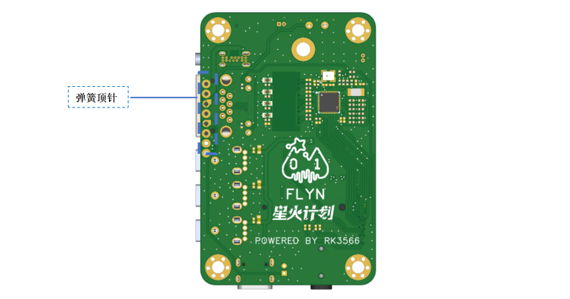
1.1 EXP Expansion Board
First, let's introduce the EXP expansion board. This board mainly uses FPC cables and spring-loaded pins (POGO PINs) to bring out the power interface, network port, USB port, SATA interface, and headphone jack from the Taishanpai development board. The interfaces are shown below:
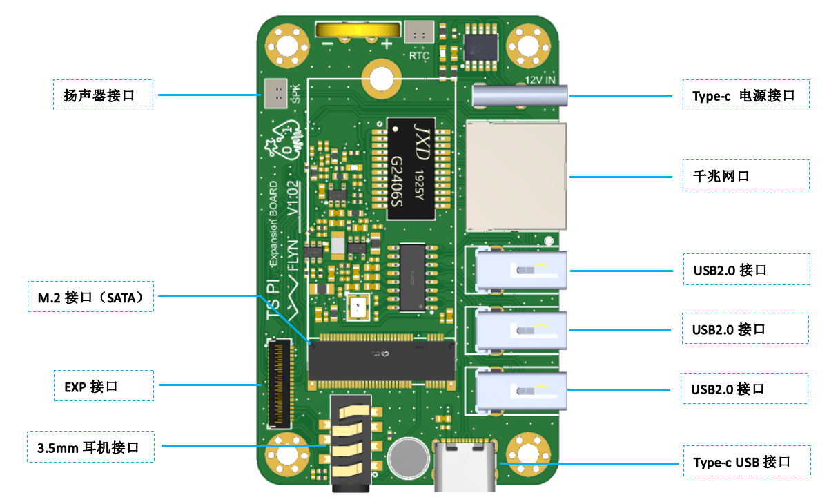
The USB expansion chip uses the SL2.0A 1-to-4 HUB chip, expanding the USB3 interface of the EXP interface into four USB 2.0 ports, facilitating the connection of external USB flash drives, keyboards, mice, etc., and can also be used to connect USB peripherals such as USB cameras for development. Note that USB3 was originally a 3.0 interface, and some of its pins are shared with SATA1. They cannot be used simultaneously. You need to change it to a 2.0 interface in the device tree, using only the USB3_HOST1_DP and USB3_HOST1_DN pins.
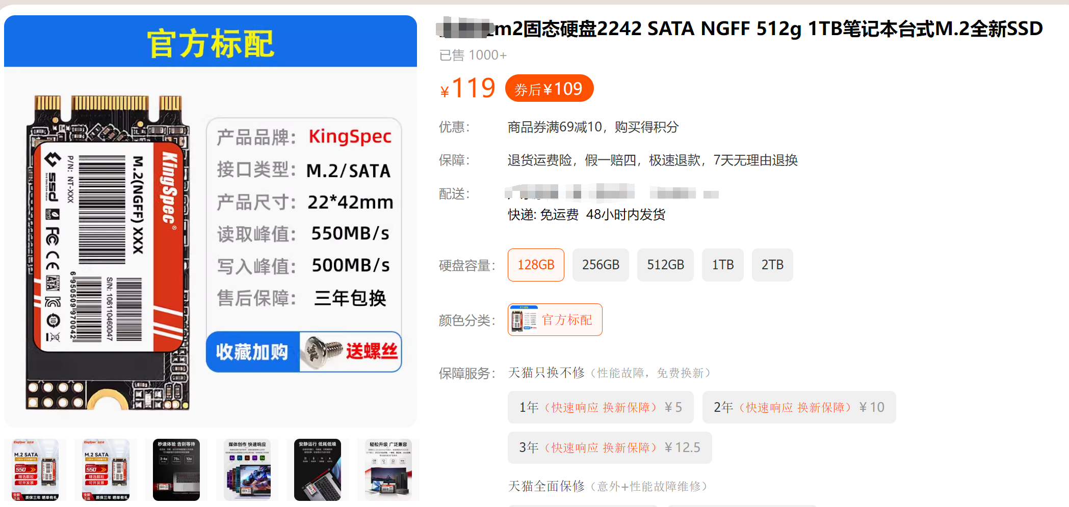
Additionally, the host controller's SATA1 interface is used to create an M.2 slot, which can connect to a 2242-inch SATA hard drive. I tested it with a 128GB hard drive I bought on a second-hand marketplace for 40 RMB including shipping. For a more reliable option, you can search for hard drives with this interface protocol on Taobao or JD.com (Note: no advertising intended). Do not buy mSATA or NVMe hard drives; the former is too large, and the latter has the wrong protocol!
The GMAC's PHY chip is the Realtek RTL8211F; refer to the expansion board design provided by LCSC for reference. This allows the host to connect to the internet via Ethernet cable.
1.2 IO Expansion Board
The IO expansion board mainly brings out the 40-pin expansion port from the Taishanpai development board to the side, and uses the PWM14 pin to design a circuit to drive the cooling fan. A DC-DC circuit is also designed to convert 5V to 12V power for the fan. This board is separate from the EXP expansion board and connects to all external expansion I/O. Users can design flexibly, such as adding an MP6050 to the board to achieve automatic screen rotation, or directly making a module to insert from the rear socket. This is the characteristic and fun of open source projects!

1.3 LCD Adapter Board
This mini-PC can be equipped with a 3.4-inch capacitive touchscreen. This screen is independent of the two expansion boards mentioned above. The capacitive screen model is HD34004C40, the RGB interface driver chip is ST7701S, and the touch driver is CST328. Related information has been uploaded to the attachment. It can be purchased on Taobao (Note: no advertising content).

Because the Taishanpai does not bring out the RGB interface, an adapter board needs to be designed to convert the MIPI interface to an RGB interface. Like most RGB screens on the market, this screen requires initialization via SPI pins. The Taishanpai MIPI interface socket only provides backlight and MIPI pins. To separate it from the IO expansion board and avoid using its IO pins, an additional SMT32G030F6P6 is added to the adapter board for initializing the LCD screen. This board references the projects of the following two open-source authors; thanks to them for their contributions:
okll's "Taishanpai MIPI DSI to RGB Adapter" project and
Fengmoxi's "Taishanpai 4-inch 86-inch Screen Adapter Board" project.

This adapter board is directly attached to the back of the LCD screen. Note that the header pins are used for burning the SMT32 firmware; it's best not to solder them, but use spring-loaded pins to insert them for firmware burning. Secure the back with insulating tape to prevent short circuits caused by contact with the LCD screen's metal backplate. The encoder switch is for compatibility with LCD screens with the same interface definition but different driver chips, such as a 4-inch RGB square screen or a 4-inch RGB rectangular screen; soldering is not required for this project. Additionally, note that the screen's backlight current is a maximum of 20mA, so the backlight current-limiting resistors R95 and R96 on the Taishanpai must be changed to 22R!!!
2. Structure
As mentioned earlier, the host has built-in components such as fans and speakers. I designed a 3D layout for these components, including the PCB board, focusing on compactness, heat dissipation, and aesthetics. (Aside: I think that for a DIY project to be attractive, aesthetics are just as important as functionality. I spend roughly the same amount of time on functional and structural design, and some projects even have functional designs completed in one day, while structural design can take several days or even a week).
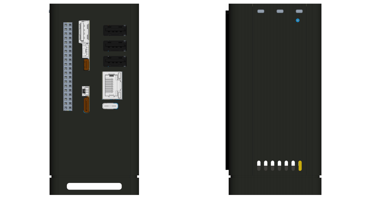
2.1 Shell Design
Thanks to the generous sponsorship of the LCSC platform, I naturally chose a CNC shell, which definitely surpasses 3D printing in terms of texture (no exaggeration). The entire shell consists of a front panel, back panel, left side panel, right side panel, top cover, and base. There are quite a few shell parts this time, and I will explain the purpose of this design below.

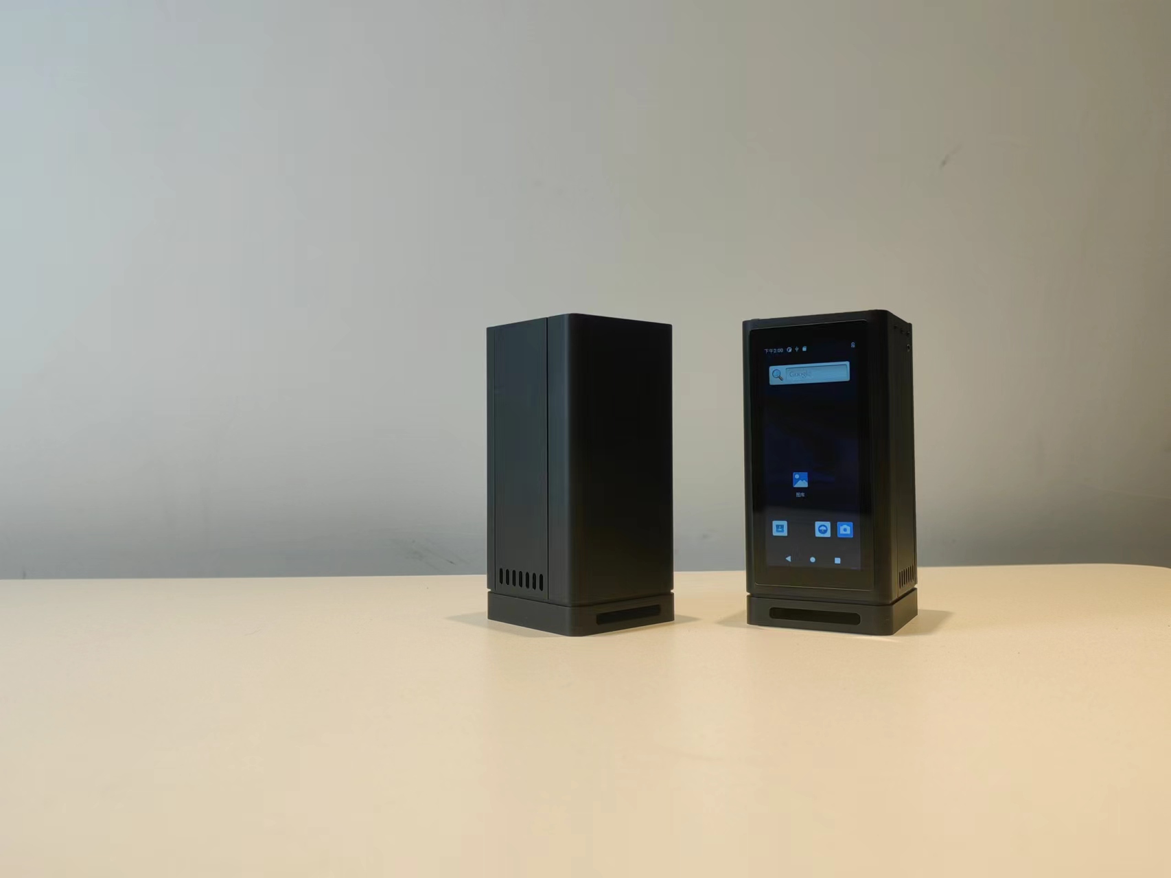
Front panel: The front panel is mainly used to install the display screen. The front panel in the picture above has a slot in the middle to install a 3.4-inch long strip screen. If a display screen is not needed, you can choose the version without the slot.
Backplate: The back panel houses the interface leads for several PCB boards; almost all interfaces are routed from the back. If the I/O expansion board has a new interface design, this backplate will need to be modified.
Left Side Panel: A left side panel is designed for convenient installation of the internal hard drive. Remove the top cover, pull the left side panel upwards to install the hard drive, without disassembling the entire casing.
Right Side Panel: For future firmware upgrades and development, the buttons and tri-color indicator lights from the Taishanpai are retained. The button and light pillars are mounted on the right side panel; simply insert the right side panel from top to bottom during installation.
Top Cover: Because of the built-in Wi-Fi antenna, the top cover uses an acrylic panel, which also allows for easy labeling. The top cover provides a Type-C USB port and a headphone jack.
Base: The base secures the internal cooling fan and the entire PCB board, and the recessed center houses the speaker, with sound emanating from the bottom.

2.2 Thermal Design
The Taishanpai development board uses the Rockchip RK3566 processor, a high-performance, low-power quad-core application processor chip primarily used in tablets, AI TV boxes, speakers with screens, facial recognition payment POS machines, e-readers, cloud terminals, video phones, and NAS storage. If you use the official heatsink, the temperature is surprisingly high during use...
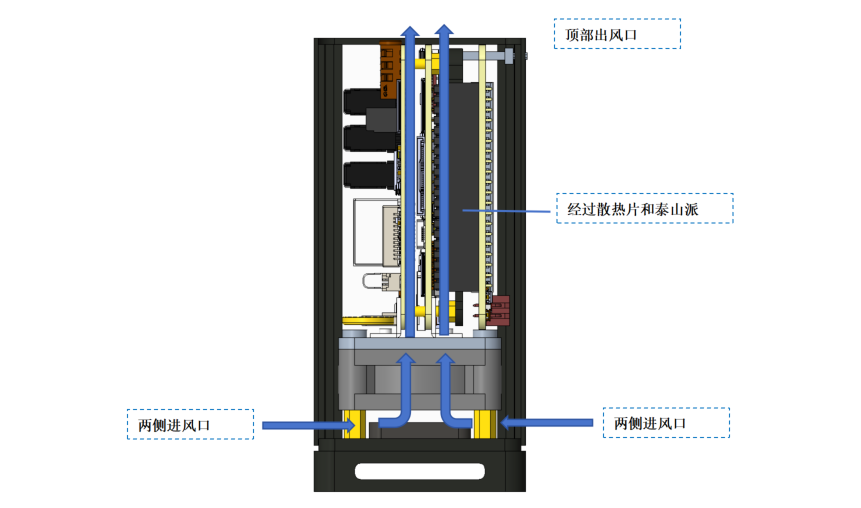
I designed a larger heatsink (unverified, the component hasn't arrived yet) sandwiched between the Taishanpai and the IO expansion board, and installed a cooling fan at the bottom. Cool air is drawn in from the bottom side and blown upwards, exiting through the vent on the top cover. The airflow loop passes through the entire heatsink and the Taishanpai, theoretically effectively reducing the internal temperature (theoretically because I lack experimental evidence).
2.3 Audio Equipment
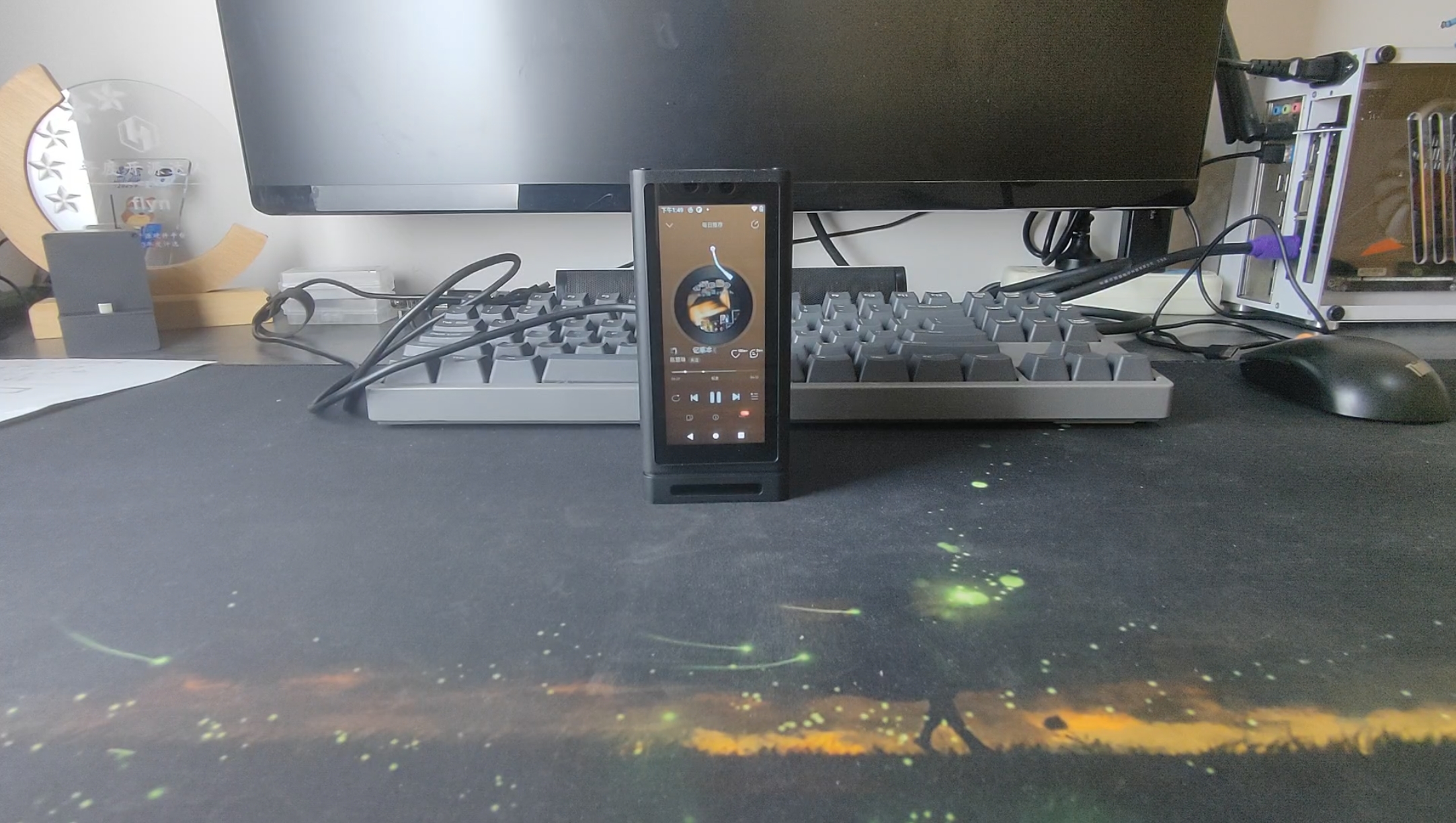
Speakers The speakers used are 8Ω 2W waterproof cavity speakers, measuring 35 * 25 mm and approximately 8 mm thick. They are designed to be mounted at the bottom, with sound transmitted through a through-hole under the base. If the volume is insufficient, you can connect external speakers via the USB port on the back.
The microphone is located at the top, with a microphone port on the top cover.
The headphone jack is also located at the top.

3. Software
3.1 STM32 Driver for LCD Adapter Board
This code is generated using STM32CubeMX and written in Keil, so it will not be explained in detail. When the STM32 detects the reset signal, it begins initializing the LCD screen. The code is relatively simple; just refer to lcd_config.c. The following is the lcd_config_task function, which runs in a loop within the main function.
void lcd_config_task(void)
{
//static uint8_t status = kStatus_idle;
static uint8_t status = kStatus_reset;
static uint32_t tick;
static lcd_t *lcd_select = NULL;
if (rst_key_is_pressed()) // Detect reset_key signal
{
status = kStatus_reset;
}
switch (status)
{
case kStatus_reset:
HAL_GPIO_WritePin(LCD_RST_GPIO_Port, LCD_RST_Pin, GPIO_PIN_RESET);
tick = HAL_GetTick();
status = kStatus_config;
break;
case kStatus_config:
lcd_select = read_lcd_selected(); // Read lcd model id
if (lcd_select)
{
if (HAL_GetTick() - tick > lcd_select->reset_time)
{
HAL_GPIO_WritePin(LCD_RST_GPIO_Port, LCD_RST_Pin, GPIO_PIN_SET);
lcd_select->config(); // Configure LCD
status = kStatus_idle;
}
}
else
{
// No corresponding LCD
status = kStatus_idle found;
}
break;
case kStatus_idle:
default:
break;
}
}
3.2 The development board
currently uses the Android system, compiled based on the SDK in the official Taishanpai documentation and the Ubuntu 18.04.6 environment.
The official SDK is basically compatible; only minor modifications to the device tree are needed. If an LCD screen is required, a touch driver needs to be added. The touch driver was written as I learned, so it's just for now. It will be uploaded to Gitee later after it's properly organized.
3.2.1 Partial Code Explanation
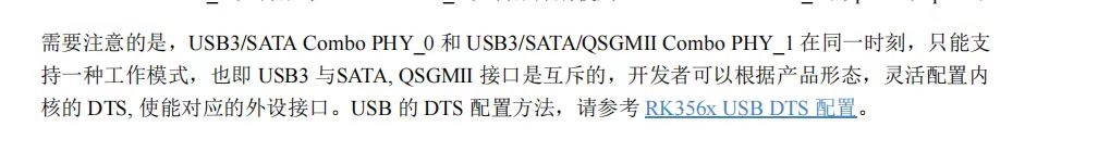
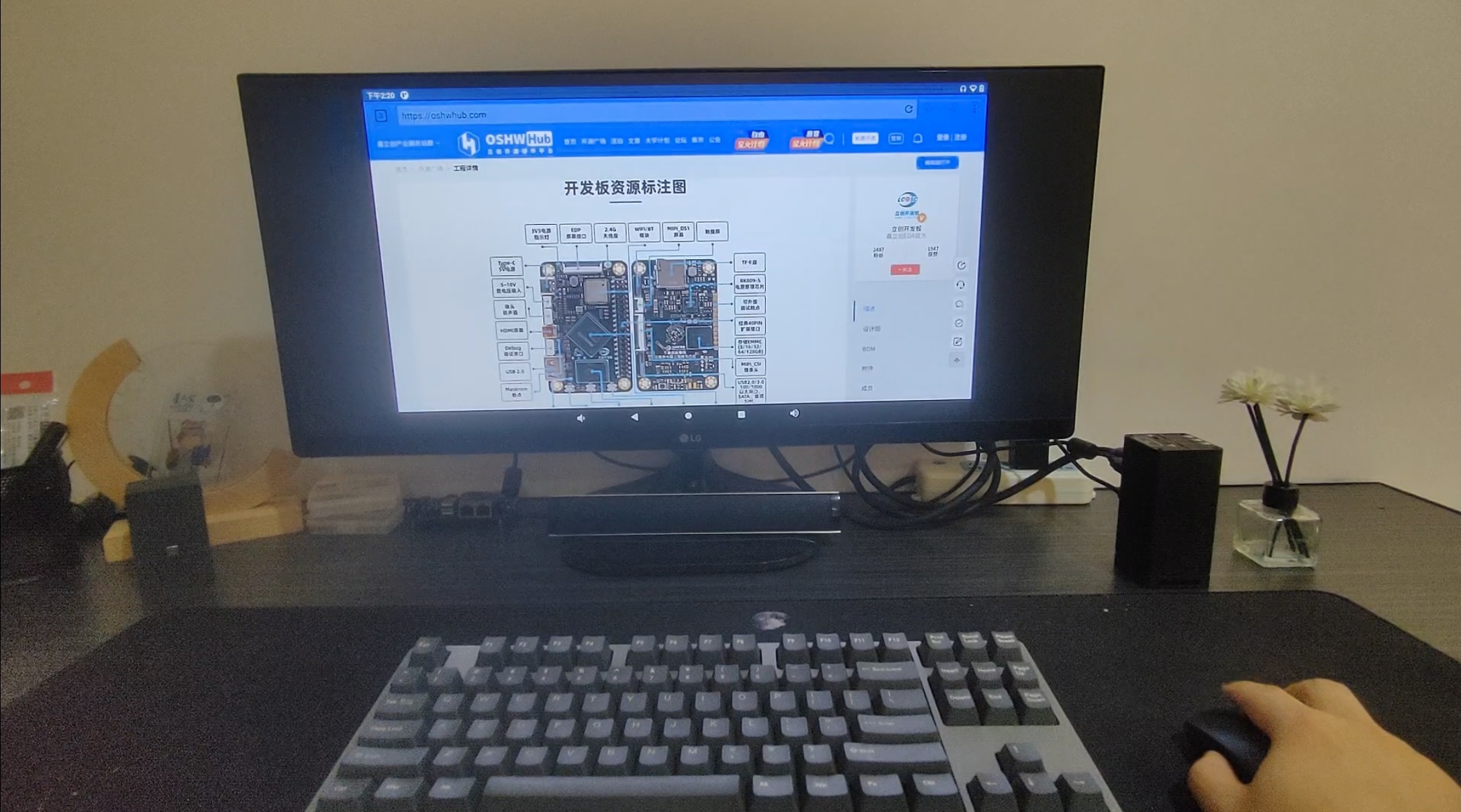
and Display Selection: The PC host can be connected to an external monitor via the HDMI interface of the Taishanpai development board, or a 3.4-inch elongated screen can be added. This can be switched by modifying tspi-rk3566-user-v10.dts. Although MIPI and HDMI interfaces can be used simultaneously, the RK3566 only allows simultaneous display on different screens. This means that when using a 3.4-inch screen, the HDMI display will also show a portrait view of that resolution, making the user experience less than choosing one of the two options. (The image below is from the Taishanpai development board documentation.)

USB 3.0 and SATA1: According to Rockchip's documentation, USB 3.0 and SATA1 cannot be used simultaneously. However, I only used the DP and DN pins of the USB, and there is no pin overlap with SATA. The resourceful Mr. Wu suggested changing USB 3.0 to be shared by both USB 2.0 and SATA, and provided a device tree modification solution. Thank you, Mr. Wu! ^^
&usbhost_dwc3 {
phys = <&u2phy0_host>;
phy-names = "usb2-phy";
maximum-speed = "high-speed";
status = "okay";
};
&combphy1_usq {
rockchip,dis-u3otg1-port;
status = "okay";
};
&sata1 {
rockchip,enable-ssc;
status = "okay";
};
* Fan Driver: A driver for the cooling fan already exists, located in `drivers/hwmon/pwm-fan.c`. Hardware control is via PWM14, but because a 2-wire fan is used, PWM directly adjusts the power supply's on/off state, resulting in significant noise during adjustment. Therefore, it's currently set to level 2 (0, 255). The fan can achieve automatic system temperature control through Linux's Thermal mechanism. I'll update this after further research (meaning I don't know how now).
* Touch Driver: The selected 3.4-inch LCD screen uses the CST328 touch chip. The seller also provided the corresponding driver code, but I didn't use it. I rewrote the driver according to the touch explanation in the official documentation. If you want to compile the touch driver directly into the kernel, please copy the driver file to the `kernel/drivers/input/touchscreen` directory and modify the Kconfig file and Makefile file in the `touchscreen` directory. Then, open menuconffig, find CST328_Touchscreen, enable it, save the configuration, compile the kernel, and then burn the boot.img file in the kernel directory separately using the **RKDevTool** tool. For more detailed steps, please refer to Section 6, "Touch Driver," in Chapter 9 of the project examples in "[Taishanpai Development Board Data](https://lceda001.feishu.cn/wiki/AhDkwcP5RiwUHXkzMVOc1JMPnBg)". I directly set it to -y in the Makefile.
source "drivers/input/touchscreen/hyn_cst328/Kconfig"
obj-y += hyn_cst328/

## 4. Assembly
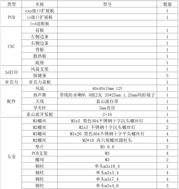
### 4.1 Bill of Materials
### 4.2 Assembly Process
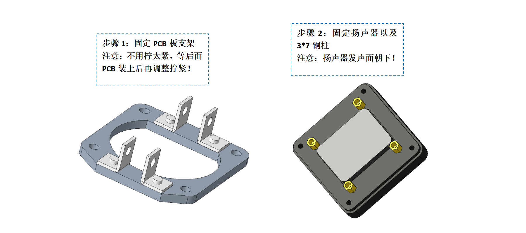
* *

* * *

* * *

* * *

* * * *

## 5. Physical Object
## 6. Documentation
### 6.1 Open Source References and Links
* Official [**Taishanpai Development Board**](https://oshwhub.com/li-chuang-kai-fa-ban/li-chuang-tai-shan-pai-kai-fa-ban) project
* okll's "**[Taishanpai MIPI DSI to RGB Adapter](https://oshwhub.com/okll/tspi-mipidsi-to-rgb-adapter)**" project
* Feng Moxi's "**[Taishan Pie 4-inch 86-screen adapter board](https://oshwhub.com/fengmoxi/taishan-pie-4-inch-86-screen-adapter-plate)**" project
** once again thanks the above open-source authors!
### 6.2 Project Resources
* 3D shell STP file: Attachment
* LCD screen adapter board driver: Attachment
* SDK and patches: To be organized
## 7. In conclusion,
this mini PC took about two months of my spare time to develop from an initial idea to a physical prototype, with many stops and starts. From the ease of drawing on the PCB to the complete ignorance of writing Linux drivers, leaving the comfort zone of MCUs and embracing Linux, I truly feel that this embrace is hard and uncomfortable... Fighting until midnight every night, the most gratifying thing is that my hair is still intact. In the future, I will conduct in-depth research and learning based on this mini PC, hoping to progress together with everyone! (Why do I feel like I've said this somewhere before? - -||)
**Always believe that every setback is a chance to accumulate strength for your future!**
Here, I'd like to thank the LCSC open-source platform, Mr. Wu, the head of the LCSC development board, for his patient guidance, and Mr. Chen, the head of the Spark Program, for his assistance and support. `emmm, the Spark Program is coming soon, and my hair, which I've been growing for two months, will only be able to use this to battle with Mr. Wu then.`
**I hope this "mini-PC" will serve as a starting point, and that more partners with an open-source spirit will join us in building a strong open-source ecosystem!**


 京公网安备 11010802033920号

 1N4749


