
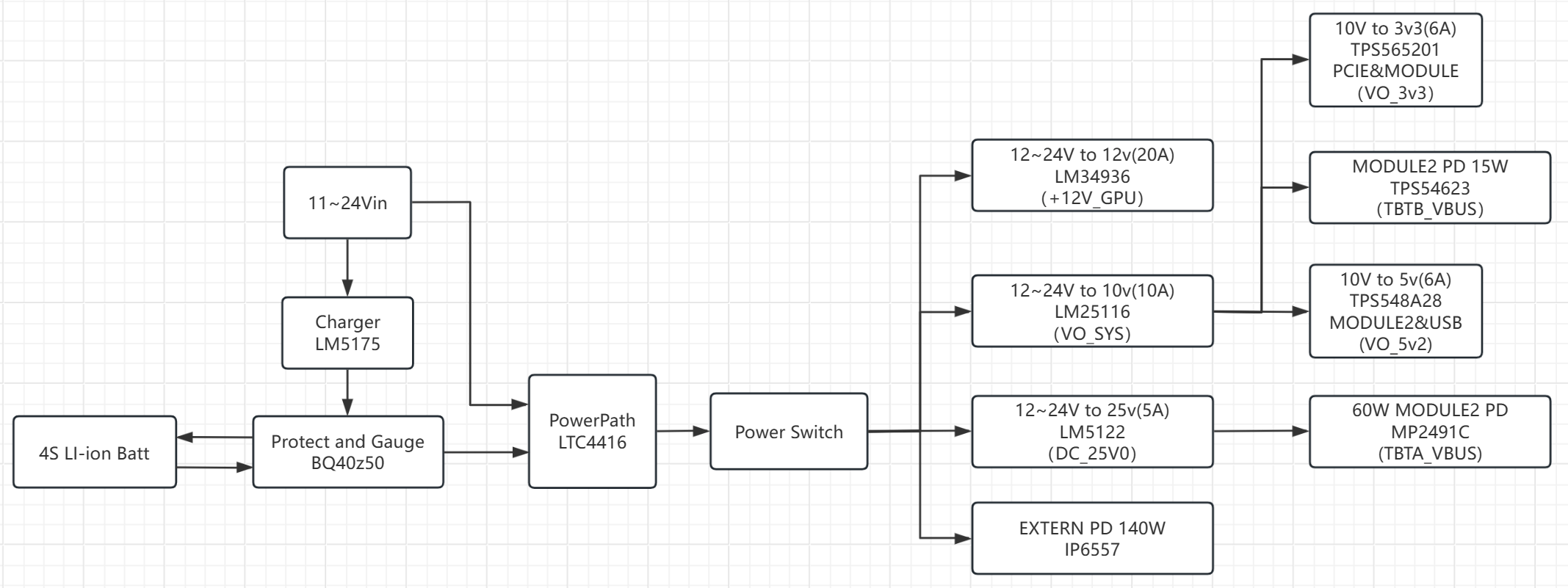
 The system power supply can operate in two states. In the first state, when powered by an external power adapter, the input from the top left (12-24Vin) is the external power adapter input. After entering the system, it splits into two paths: one goes to the Charger, which charges the battery via the BQ40z50 fuel gauge; the other goes to the PowerPath circuit. The PowerPath circuit checks if the main power supply is functioning correctly. If so, it turns on the main power discharge MOSFET and turns off the backup power discharge MOSFET. The main power supply then powers the subsequent circuits. The subsequent PowerSwitch is a power switching circuit that uses a PMOSFET as the high-side switch. When the user closes the mechanical switch, the PMOSFET conducts, powering on all subsequent power supplies.
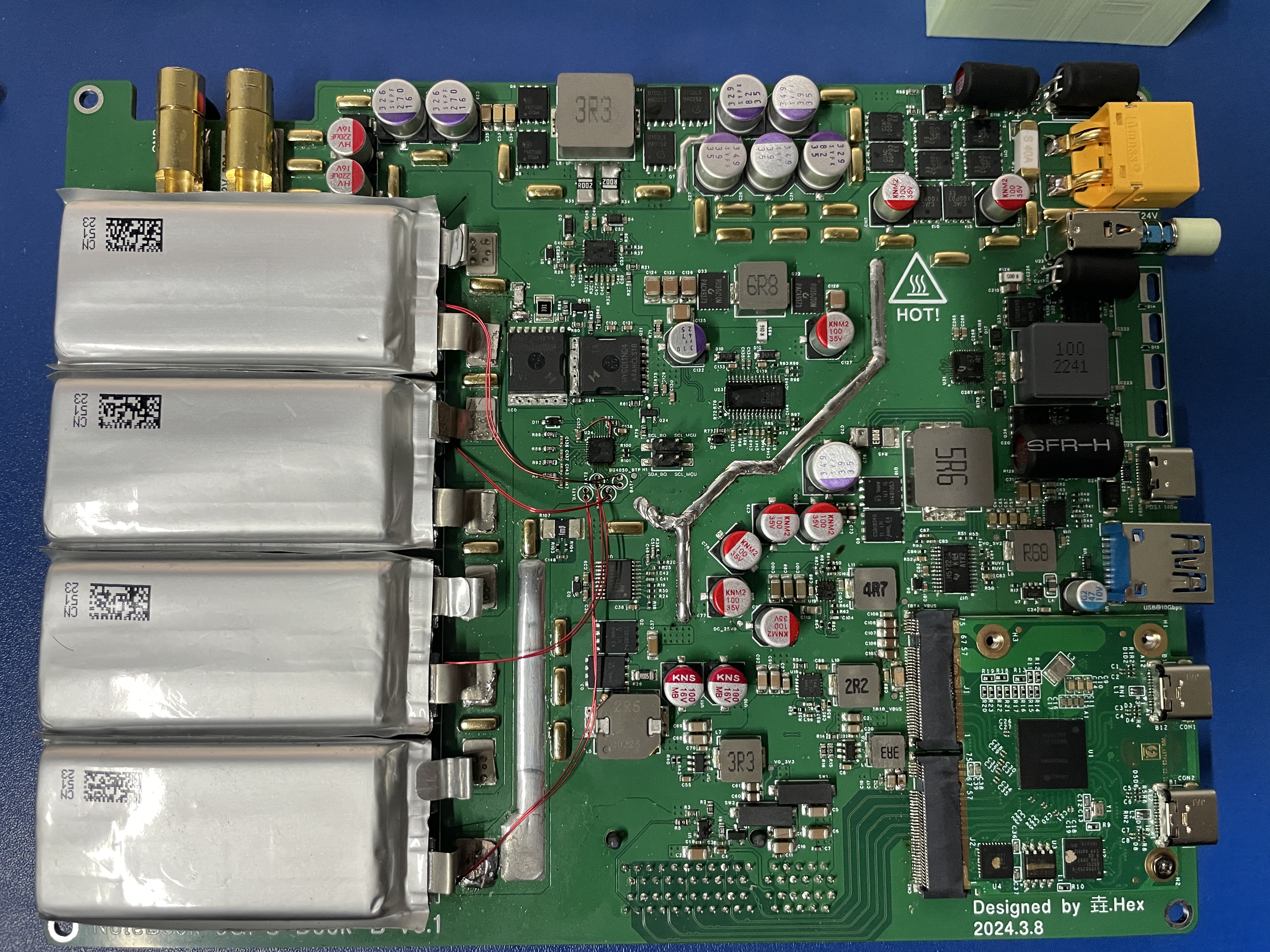
 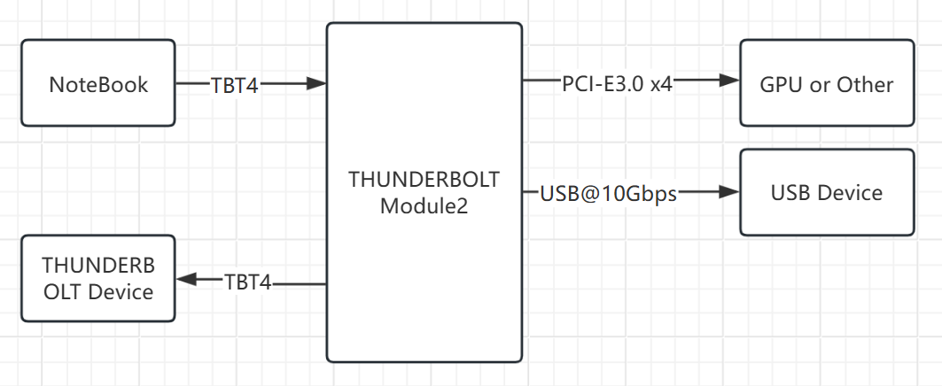 Motherboard PCB 3D diagram is shown in the figure:
 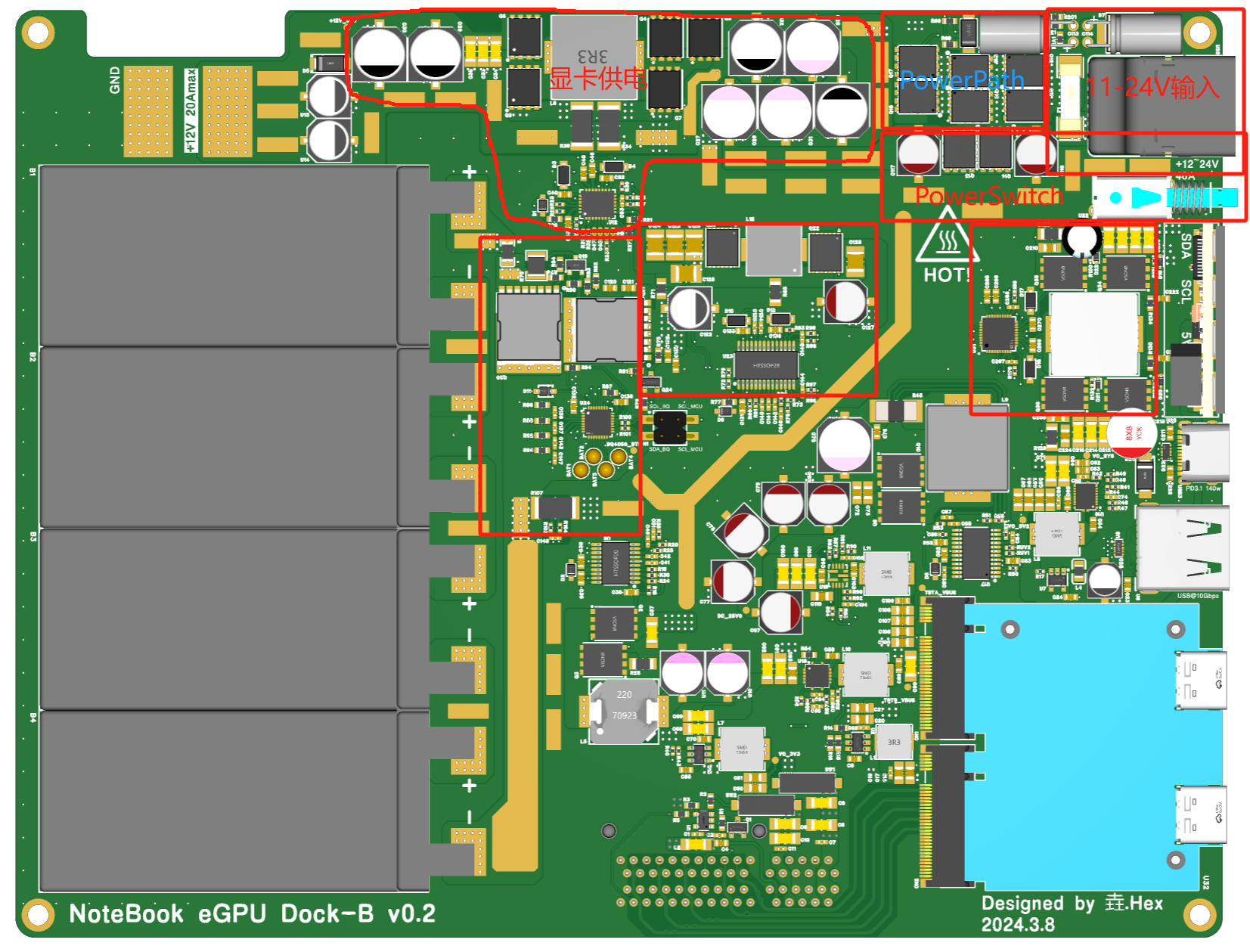 MCU board hardware block diagram is shown in the figure:
  The MCU board is responsible for accessing battery parameter data from the BQ40z50 fuel gauge, power failure alarm, and temperature detection. The MCU selected is STM32F103C8T6.
  1.2 Introduction to the graphics card power supply (LM34936):
  1.3. PowerPath Module Introduction :
  Channel 1 in the figure represents the power adapter output voltage, and channel 2 represents the voltage output by the PowerPath circuit. At approximately 240ms, when the external adapter is powered off (channel 1), the PowerPath circuit switches to the auxiliary power supply, and the voltage drops to the auxiliary power supply voltage (channel 2).
 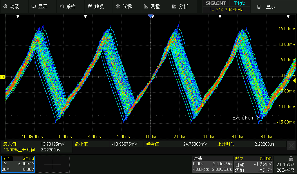 Ripple magnitude is 24mV.
 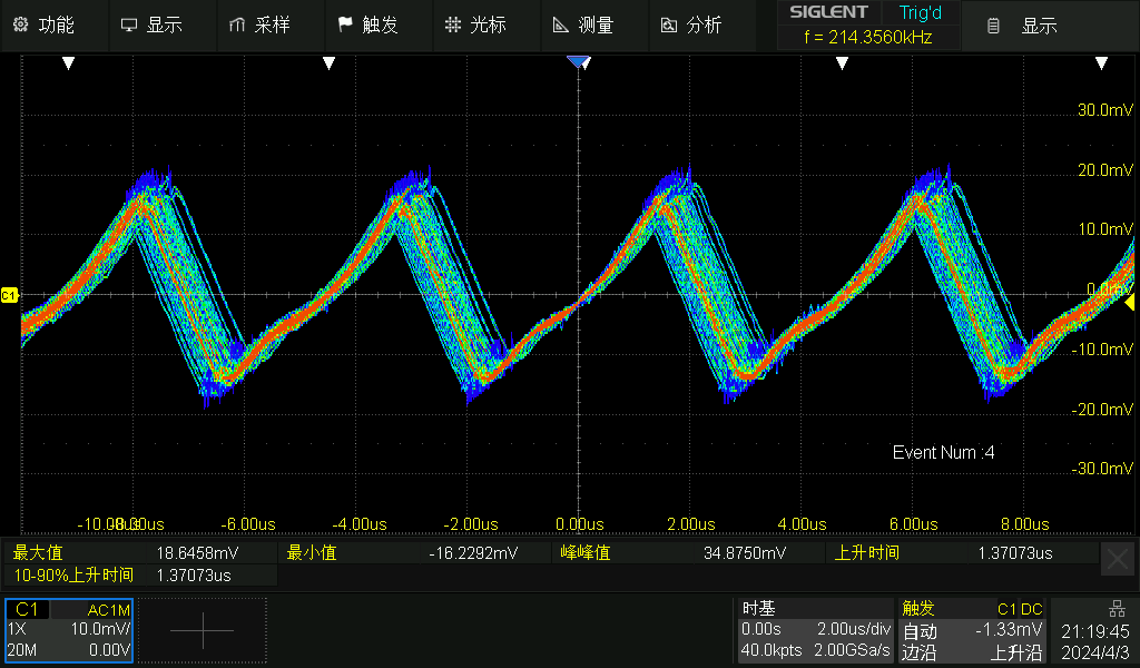 Full-load ripple magnitude is 35mV.
 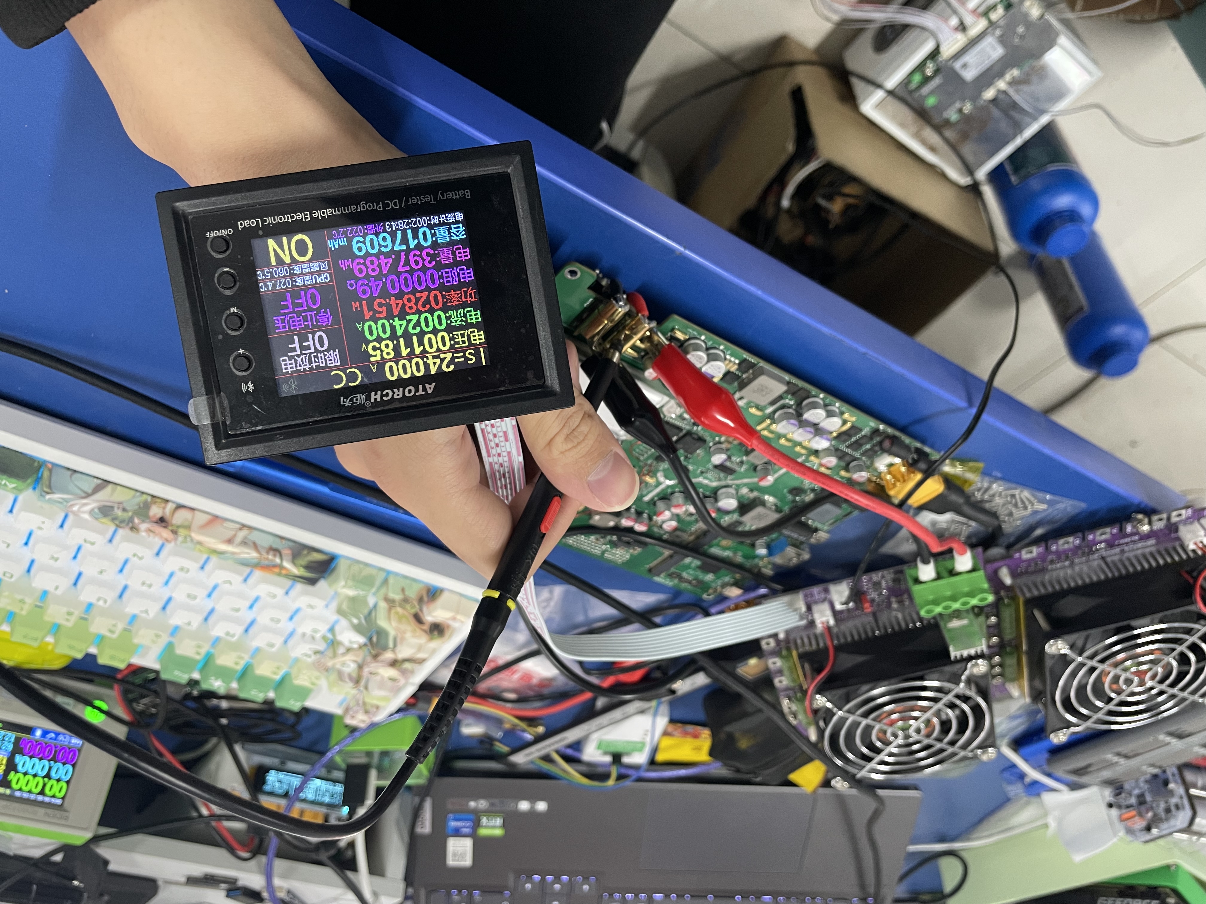 A dynamic electronic load was connected to the power supply. A 100Hz 1100mV square wave signal was generated using a signal generator to control the electronic load to produce a step current signal. The resulting dynamic response of the power supply is shown in the figure:
 In the diagram, channel C2 represents the power supply's output current, and channel C1 represents the power supply's voltage. Channel C1 enables AC coupling, with a bandwidth limit of 20MHz. As the current increases from 0A to 11A, the system overshoot is approximately 72mV; as it decreases from 11A to 0A, the overshoot is 61mV, indicating good dynamic response.
 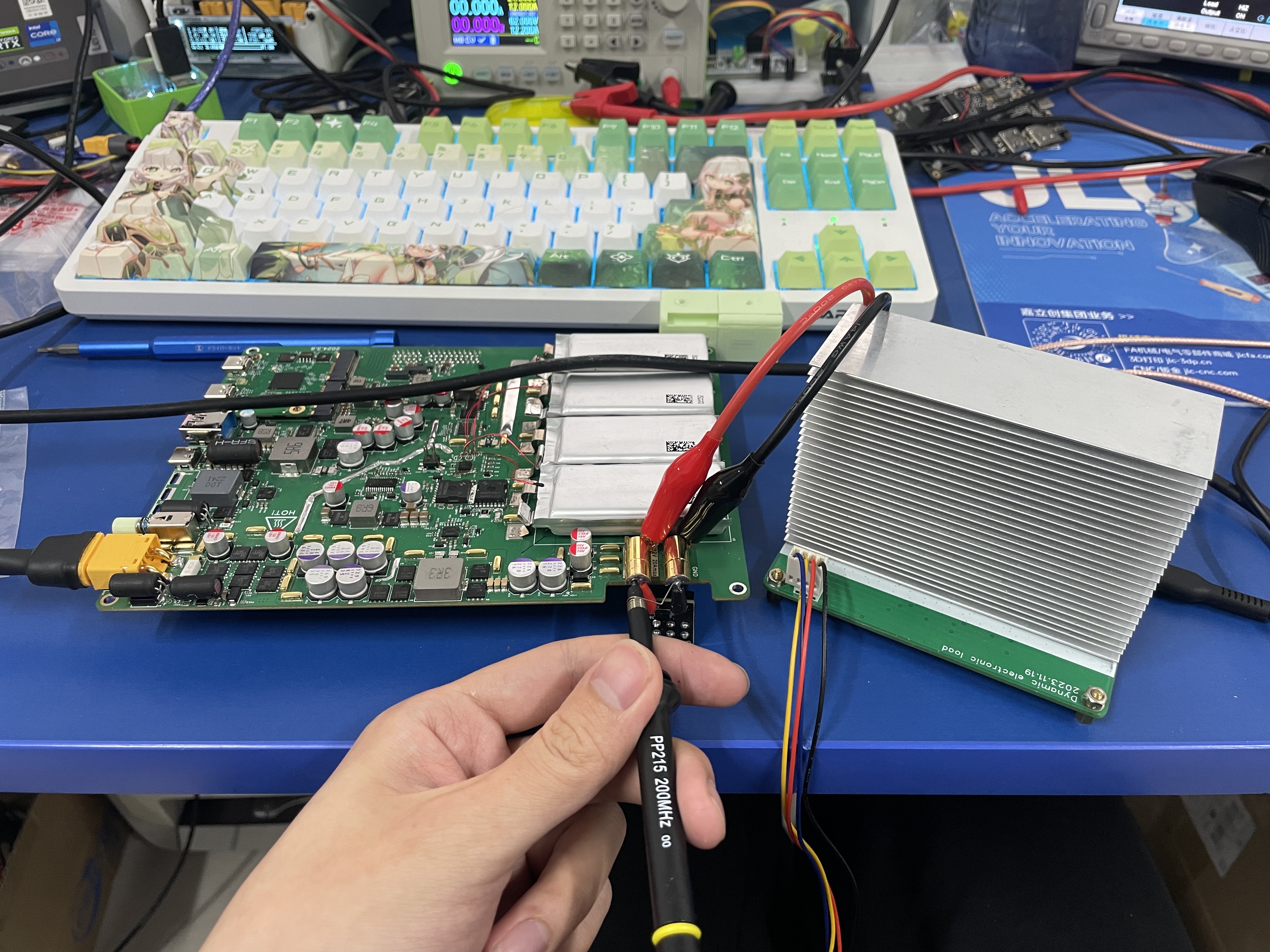 2.2 Thunderbolt 4 Bandwidth Test:
  Graphics Card: MSI AERO RTX3060TI LHR
 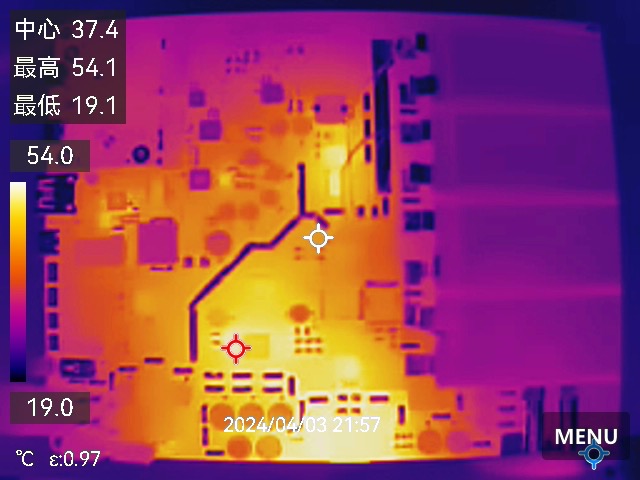 when the adapter was used for power supply, the battery was not fully charged, the system was under full load, and no heatsink was installed:
 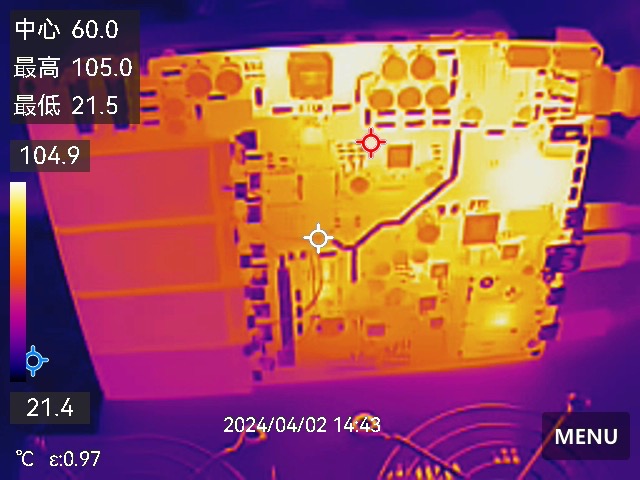 Test Equipment: Hikvision K20

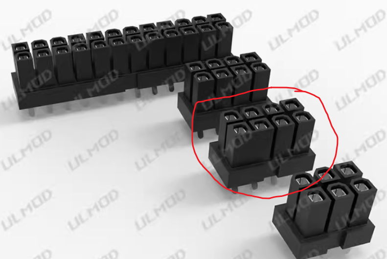
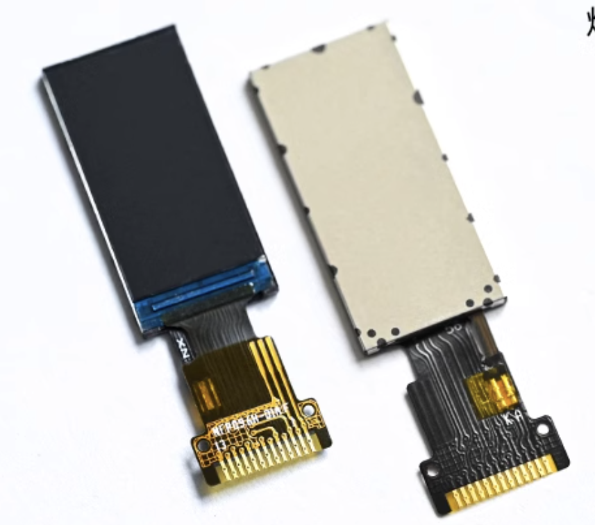
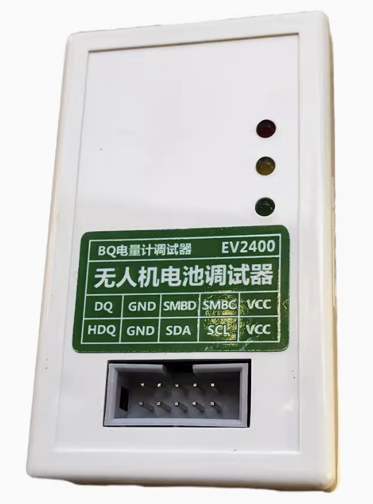
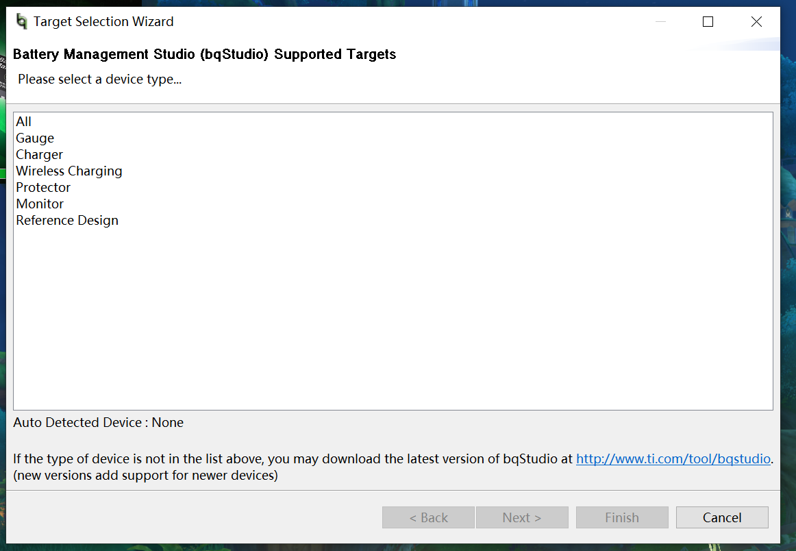
 as shown in the picture; 7*5*0.3mm cold solder pads, used to connect the battery to the motherboard of the graphics card enclosure, 8 are needed, as shown in the picture; 0.96-inch LCD screen, ST7735S main controller, used for the MCU board to display system parameter information, as shown in the picture; screws: M2*4, M2*16, M3*8 ; studs: 4; M3*45+10; power adapter: 12~24V is acceptable, depending on the graphics card used. I used an RTX3060Ti graphics card. The graphics card enclosure also charges the laptop while working, using a HOTA 245W*2 GaN power supply, which works stably in actual testing. If using a 12V power supply, the full-load voltage drop should not be too large. If the input voltage is less than 10.8V, the system will consider the external power supply abnormal and switch to battery power. 8mm heat shrink tubing is used for capacitor aluminum shell insulation. 2. PCB Fabrication 2.1 Prototyping This project requires prototyping three PCBs: GPU_Dock_MotherBoard, MCU_Board, and an 8-pin connector. When ordering the GPU_Dock_MotherBoard PCB, select the JLC04161H-3313 laminated structure. Impedance control is required, ±20%, and the board thickness is 1.6mm. The other PCBs are also 1.6mm thick and do not require impedance control. 2.2 Soldering 2.2.1 Some Precautions Solder the battery last! Solder the battery last! Solder the battery last! The PCB component layout is relatively dense. If SMT is not selected, it is recommended to solder the chips first, then solder the resistors and capacitors; otherwise, if the chips have solder joints, the soldering iron will not be able to remove them. After all components are soldered, do not insert the Thunderbolt Module 2 module. Power on and test first. Once the power supply is normal, insert the module and test again. If the computer recognizes the graphics card, perform a stress test. If no problems occur, then solder the battery, being careful not to short-circuit. 2.2.2 PCB after soldering. 2.2.3 Soldering Precautions: Ensure insulation on the front of the PCB: The NTC resistors with reference numbers BAT1~BAT4 are MF52B103F3450, or you can use B3450 10K resistors instead. Since these NTC resistors use through-hole pads, the graphics card backplate directly contacts the front of the PCB. You need to grind the leads flat on the front of the PCB and then apply insulating paper to prevent the graphics card backplate from short-circuiting the resistor. The same applies to reference numbers C217 and U22. Ensure capacitor insulation: Capacitors with reference numbers C113, C114, C217, and C221 need to be covered with heat shrink tubing before soldering to prevent short circuits in the aluminum casing. Note the battery soldering order: Solder the battery with reference number B4 first, then B3, and so on. NTC Resistor Locations: This project uses a total of 6 NTC resistors. Four NTC resistors detect battery temperature, and two NTC resistors detect the temperature of the graphics card power supply and power path management. The four NTC resistors for detecting battery temperature need to be glued to the battery; 704 silicone rubber can be used. The NTC resistor for the graphics card power supply needs to be glued to the inductor with the L6 bit number, and the NTC resistor for power path management needs to be glued near Q14 and Q13. 2.3 After programming and PCB soldering, power on the device and check if each power supply is working properly. If all power supply voltages are normal, the module and graphics card can be inserted. After insertion, use Thunderbolt 4 to connect the graphics card enclosure to the computer. The computer should be able to recognize the new GPU. If it is recognized, it means that the soldering of the main components is correct. 2.3.1 Fuel Meter Configuration: Configuring the fuel meter requires an EV2400, which can be purchased from Taobao for around 120 RMB. The EV2400 is shown in the image. You also need to download Battery Management Studio from the Texas Instruments website, or use the one uploaded to your cloud drive. Connect the debugger's SMBD and SMBC interfaces to the SDA_BQ and SCL_BQ pins of the graphics card enclosure's motherboard, respectively. Since the PCB does not have a pre-installed GND interface, you can use a Thunderbolt cable to connect the computer and the graphics card enclosure's motherboard, ensuring they share a common ground. After connecting, open Battery Management Studio. Normally, this interface should pop up: If this interface appears, "Auto Detected Device: None," it indicates that the fuel gauge and computer have not communicated successfully, as shown in the image. At this point, you can select any device to enter the configuration interface and check if the EV2400 is successfully connected to the computer. If the software can read the EV2400 version, the EV2400 connection is fine. You need to check for any issues with the circuit soldering.
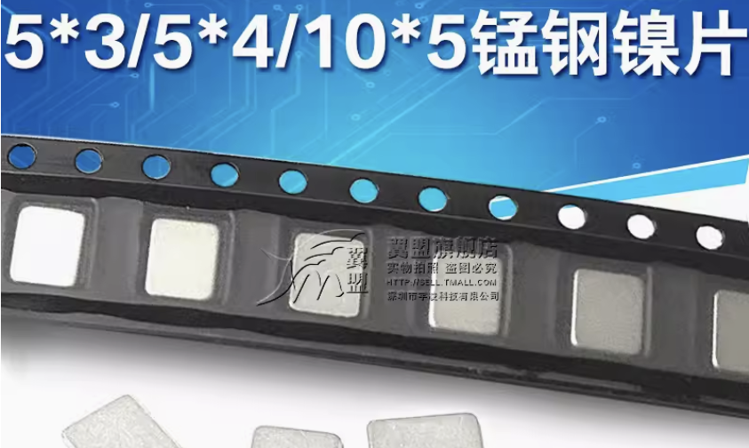

 If the EV2400 version number cannot be detected, check if the EV2400 is properly connected to the system and whether Windows provides a prompt after plugging in the EV2400. If the system provides a prompt but the host computer software still cannot detect the version, it may be a system environment issue. You can try running Battery Management Studio on another computer or in a virtual machine.
 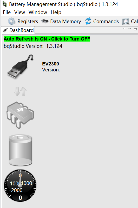 The fuel gauge on the PCB is BQ40Z50-R1, which is flashed with R1 firmware by default. The configuration in the cloud drive link is based on R2 firmware and needs to be upgraded. Refer to the fuel gauge configuration video for details.
All reference designs on this site are sourced from major semiconductor manufacturers or collected online for learning and research. The copyright belongs to the semiconductor manufacturer or the original author. If you believe that the reference design of this site infringes upon your relevant rights and interests, please send us a rights notice. As a neutral platform service provider, we will take measures to delete the relevant content in accordance with relevant laws after receiving the relevant notice from the rights holder. Please send relevant notifications to email: bbs_service@eeworld.com.cn.
It is your responsibility to test the circuit yourself and determine its suitability for you. EEWorld will not be liable for direct, indirect, special, incidental, consequential or punitive damages arising from any cause or anything connected to any reference design used.
Supported by EEWorld Datasheet
EEWorld
subscription
account

EEWorld
service
account

Automotive
development
community

Robot
development
community

About Us Customer Service Contact Information Datasheet Sitemap LatestNews


Room 1530, 15th Floor, Building B,
No.18 Zhongguancun Street,
Haidian District,
Beijing, Postal Code: 100190
China
Telephone: 008610 8235 0740
 京公网安备 11010802033920号

 LBN140A49


