Project Parameters
: Dimensions: 52x52x16mm (Width x Length x Height)
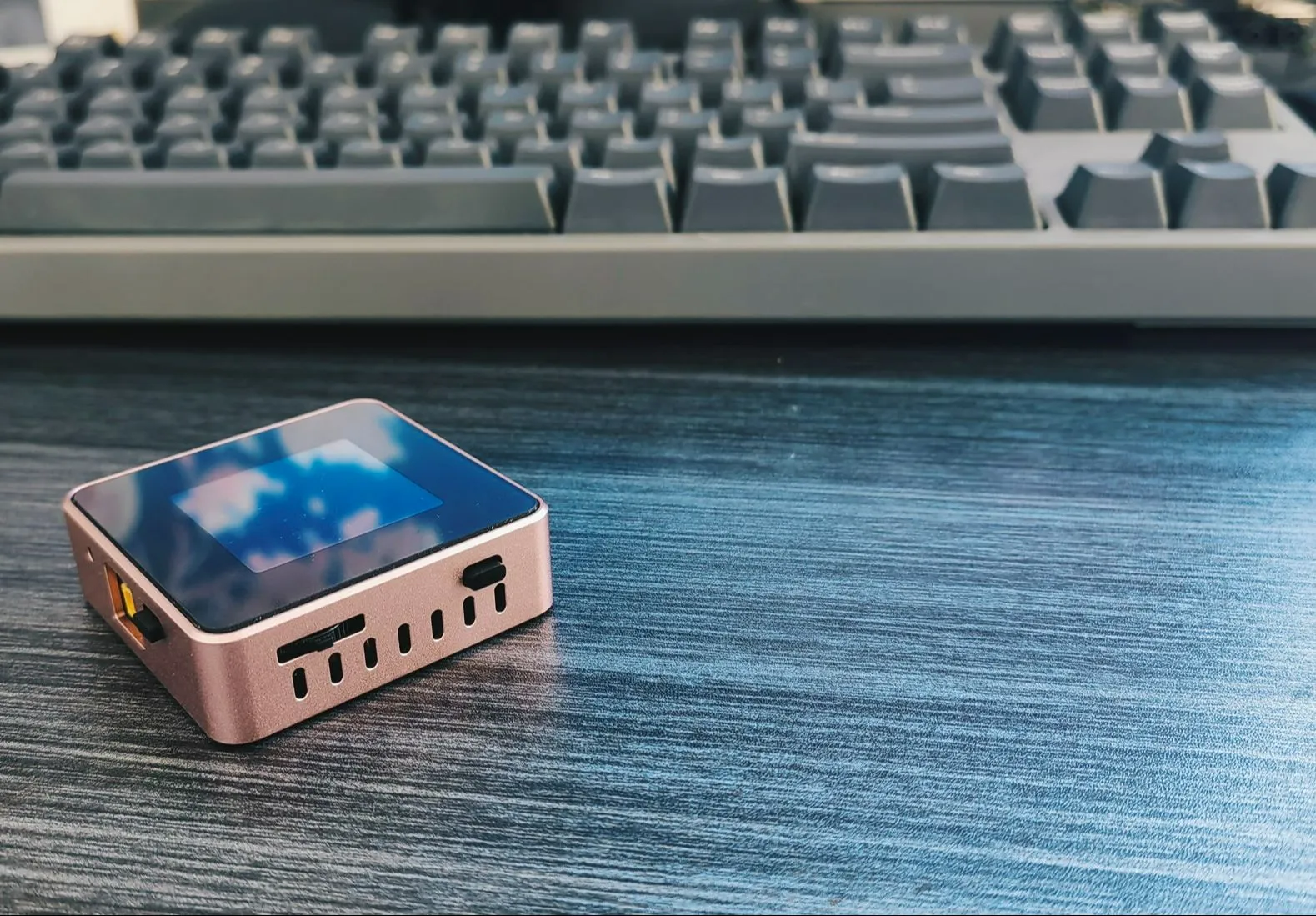
Interaction Method: 1.54-inch 240x240 resolution TFT screen, 1 rotary switch, 2 tactile switches
Power Input Interface: Type-C port (supports PD protocol), XT-3.0 male connector, 4mm banana plug interface (3D shell optional)
Power Output Interface: Power metering port Type-C, adjustable power output XT-3.0 male connector, 4mm banana plug interface (3D shell optional)
Adjustable Power Output Range: 0.4-35V, 0-5A
USB Power Metering: PD protocol detection, QC protocol
Open Source License
: This project is licensed under the "CC-BY-NC-SA 4.0" Creative Commons Attribution-ShareAlike license. Commercial use is prohibited. Please indicate the source when reprinting.
Open Source Code: https://gitee.com/yllff/flpower
Project Attributes:
This project is being publicly released for the first time and is my original work. This project has not won any awards in other competitions.
Project Update
2024/4/2: Added some introductory content and updated the Core V2.1 board.
【【Open Source】Mini CNC Power Supply (Part 1) 【Daily Fun for Electronic Engineers】】
The Core V2.1 board has replaced the encoder, adopted a pulsator switch to reduce costs, and brought out the SWD port and serial port. This is for future feature additions. Note that this version is incompatible with previous casings. Code is compatible.
Added some circuit and code descriptions.
2024/11/10: Updated the Core V3.0 board, Power V3.0 board, and Panel V3 acrylic panel.
【【Open Source】Does My Brother Have a Girlfriend? Do You Mind Having Multiple Watches? ?】
Updated the entire structure, redesigned the internal PCB board,
readjusted the code architecture, updated the UI interaction, and ported Cherry USB, Cherry DAP, and other code to implement virtual serial ports and DAPLINK.
2024/11/13: Supplemented documentation.
2024/11/17: Supplemented documentation.
U21 and U22 on the core board and U21 on the power board are not feedthrough capacitors; they are used for shorting! Some replica builders have already fallen into this trap!
After burning the firmware to the board, it needs to be connected to a PC to import calibration coefficients. Please refer to the attached video.
Power board C7 and C8 have been changed to 20pF; the project files have been updated.
Updating features include:
VCP virtual serial port function (implemented in version V3.0)
, ammeter measurement (implemented in version V3.0)
, DAPLink function (implemented in version V3.0)
, 0-50V waveform sampling channel (this function will be removed)
, 2S battery base module for scenarios without external power supply
, and 4S battery base module for constant current and constant voltage charging of the battery in scenarios without external power supply
(to be implemented).
Project Introduction:
1. The hardware
PCB board consists of two parts: a core board and a power board. They are connected by double-row pins and fixing nuts, and the layout takes into account the height of the PCB stack-up. The core board is a 4-layer board, and the power board is a 2-layer board, with resistors and capacitors primarily using 0603 packages. The main controller is the Arteli AT32F403ARGT7, an Arm Cortex M4 core, 1MB Flash, 96K RAM, and a 240MHz clock speed. It provides three power input methods: Type-C, XT30, and a 4mm banana plug. The built-in FUSB302 enables PD protocol detection. The adjustable power control chip is the SC8701, which can achieve buck-boost output. This design broadens the application scenarios; for example, if only a 5V power supply is available, it can output 2-30V. Alternatively, it can be used with 18650 batteries in scenarios without an external power source. The USB power meter and adjustable power input interface share the same Type-C interface.

1.1
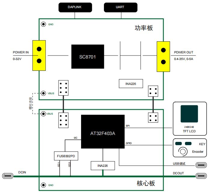
When the frame is used as a power supply, the power is connected to the DCIN (Type-C port) of the core board. If it is a charger with PD protocol, it can be tricked into maximum power mode via FUSB302 (I used a 20V 4.5A charger in my test), and then connected to the power board through the studs between the two PCB boards. The control signals of the core board are connected to the power board through a dual-row header.
The board has compatibility design; there are two shorting points on the core board and one shorting point on the power board. In this version, the shorting method of the power board is as follows:

The shorting method of the core board is as follows:

1.2 The structural
shell adopts an integrated middle frame plus a base plate and an acrylic panel structure. The acrylic panel can protect the LCD screen to a certain extent. I still designed two sets of drawings: 3D printed and CNC aluminum alloy. The 3D printed shell size is 53x53x16mm, and the aluminum alloy shell size is 52x52x16mm. In addition, when designing the PCB size, I considered the size of an aluminum alloy profile, which should be more suitable, but it has not yet been verified. I will wait until JLCPCB adds CNC technology to the profiles next year.
The 3D printed shell has four screw fixing points on the middle frame. The base plate is directly fixed to the PCB board and designed to be flat. It is best to use metal material for heat dissipation. It is recommended to apply thermal conductive silicone to the MOSFET to ensure full contact with the base plate. After the two PCBs are connected, they are fixed to the middle frame through solder terminals on the power board. The advantage of this type of shell (nylon material is recommended for its high temperature resistance) is that it is much cheaper than the cheaper CNC. The disadvantage is that it is a bit soft after printing. Compared with the first version, the middle frame structure is more beautiful and sturdy, and the separation of the base plate can increase heat dissipation.
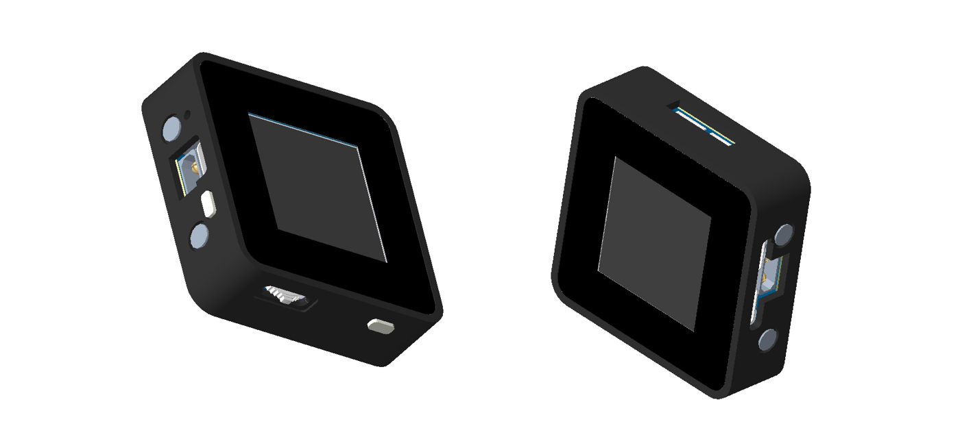
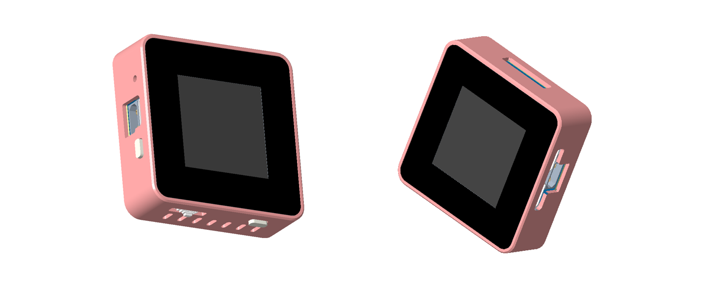
The shape of the CNC aluminum alloy shell is shown in the figure below, and it is fixed by four screws at the bottom. The advantage of this type of shell is that it has a good texture and hardness, which accelerates heat dissipation. The disadvantage is that it is expensive! Also, pay attention to the connection of the shell to GND!
1.3 Principle Analysis
1.3.1 Core Circuit Power Supply Design
The core part of the mini power supply can be powered through the power supply side (USB2) or through the debugging USB port. When both are powered at the same time, the power supply from the debugging USB port side will be selected through the power switching circuit. The power switching circuit is shown below. Let's analyze it briefly. First, when the power supply is on, U11 (ME3115AM6G) outputs VCC1 with a voltage of 3.7V, which is then output to VCC through the body diode of Q5. Simultaneously, because the gate of Q5 is grounded through R27, the drain and source are connected, reducing the power consumption caused by the voltage drop across the body diode of Q5. At this time, 3.3V is obtained through U10 (ME6211A33M3G-N). When power is plugged into the debugging USB port, the EN pin of U11 is pulled low because it is connected to the GND pin of the debugging USB port, and VCC1 becomes 0V. At the same time, the gate of Q5 has a voltage of 5V, while the source of Q5 is approximately 4.4V due to D3. Since Vgs > 0, Q5 is cut off. In this case, VCC is powered solely by VCC2. The advantage of this circuit is that when powered from the power supply side, there is little loss due to the conduction of Q5. Furthermore, when both power supplies are applied simultaneously, the power supply to the power supply side can be shielded, eliminating internal circuit losses and facilitating accurate calculation of the losses in the input and output sections of the CNC power supply.

1.3.2 Adjustable Voltage Design
The hardware utilizes the SC8701 power control chip, a synchronous 4-power transistor Buck-Boost controller. Its output voltage can be higher, equal to, or lower than the input voltage, significantly saving overall space. This chip also provides current limiting protection. Its main characteristics are an input voltage range of 2.7V to 36V and an output voltage range of 2V to 36V, adjustable via a PWM signal. A drawback is that the minimum adjustable output voltage is only 1/6 of the maximum set voltage. That is, if the maximum output voltage is designed to be 30V, the minimum adjustable output voltage is 5V. This is because when the PWM output is 0, Vout = 1/6 Vset.
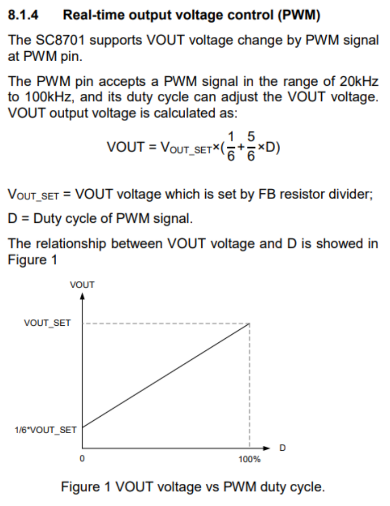
So, is there a way to widen the adjustable range of the output voltage? The answer is yes. We can solve this from another angle by keeping the PWM control pin output high and adjusting the resistor at the FB pin. According to the formula in Figure 6, we know that the resistance values of Vout and RDown are inversely proportional. If we keep the PWM control pin high, that is, let the SC8701 output the maximum set value Vout_set, then changing RDown will also change the output voltage.

However, we need to use an MCU to control the output, so we need to design a circuit. The Air32f103cct6 has a DAC function, but the 12-bit resolution is not enough. The circuit in the figure below can be used to convert the 16-bit resolution PWM signal into an analog signal and convert the voltage range to 0-V_REF.

The DAC signal is connected to the FB point through a resistor. By adjusting the amplitude of the DAC signal, the output voltage can be set. The principle analysis is as follows: when the DAC output is 0V, the current flow is as shown in the figure below. The two resistors are equivalent to parallel connection, and the maximum output voltage Vo is 1.22*(1+100k/((6.2k+2k)/2)), which is about 30.97V. The actual test is about 30.2V, mainly due to the error in the resistance value.

When the DAC output is the reference power supply (2.5V), the current flow is shown in the diagram below. The current flowing through R23 is almost 0A because after voltage division, the voltage at point FB is already 1.22V. Ideally, the SC8701 will not output any voltage, Vo=0V. Actual testing shows approximately 1.4V, mainly due to the instability of the reference power supply and resistance errors. Therefore, when the output DAC voltage is in the range of 0-2.5V, the ideal output voltage range is 0-30.9V, thus achieving a wide voltage output range. The SC8701 is labeled as having an output of 2-36V in the documentation; however, the internal workings have not been thoroughly investigated, and it is uncertain whether the minimum output is 2V.

2. The
MCU software code is divided into two parts: bootloader and app. The bootloader provides a simulated USB drive drag-and-drop upgrade function, allowing for app firmware upgrades without additional software tools, which is quite convenient. The app code is based on FreeRTOS+LVGL, the IDE uses Keil 5.38, and the GUI is generated using SquareLine Studio. The bootloader firmware is downloaded via Keil or JFlash.
2.1 Application Firmware Update:
After flashing the bootloader firmware, the application firmware can be upgraded easily. The specific steps are: first connect one end of the USB cable to the computer, then press and hold the '<' key on the mini power supply and insert the other end of the USB cable into the debugging port. The computer will then eject a USB drive named "FL POWER". Open the USB drive; it will contain a TXT file named "READY". Drag and drop the firmware file to be updated (bin or hex format) into this USB drive. The USB drive will be re-recognized, and the "READY" TXT file will be updated. "SUCCESS" indicates a successful update.
2.2 GUI Interface
: The interface is generated using SquareLine Studio, a visual drag-and-drop UI editor that allows for quick and easy creation of beautiful graphical user interfaces for embedded and desktop applications. Official website: https://squareline.io/. It is free for personal use after download and installation, but is limited to designing only 5 UI interfaces and placing 50 controls. Simple software settings allow for easy and intuitive implementation of animation effects.
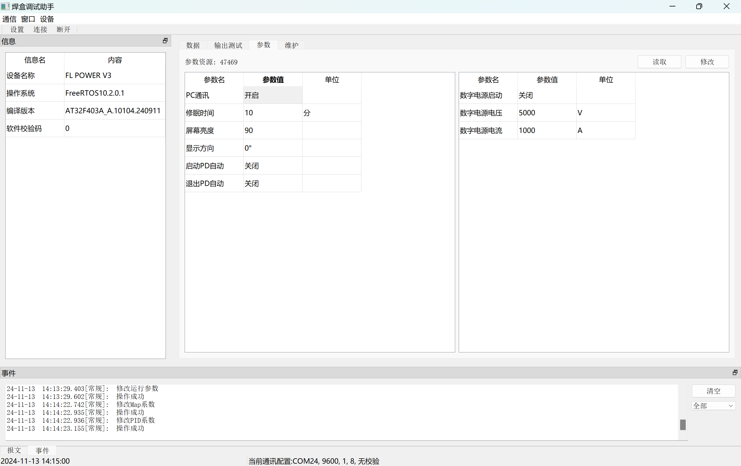
2.3 Debugging Host Computer
: The host computer is compatible with the previous soldering station and currently allows for parameter setting and calibration. The power supply connects to the PC via USB, enabling virtual serial communication.
2.4 Code Analysis
2.4.1 App Application Code
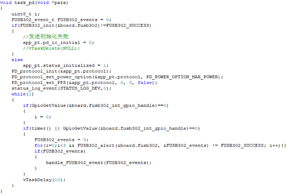
The app code is based on FreeRTOS + LVGL. After BSP initialization, multiple Tasks are created, as shown in the figure below.
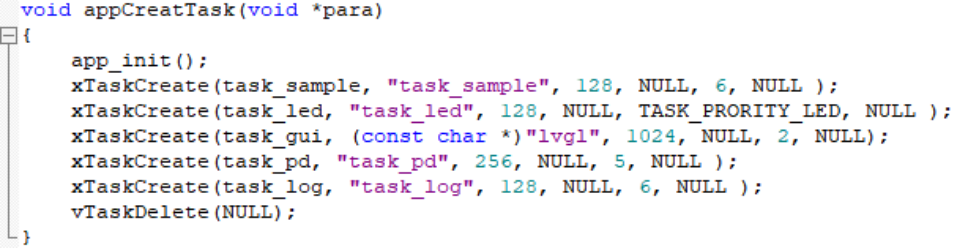
Task_sample mainly collects and calculates the voltage and current values of each channel, task_gui is responsible for LVGL operation, and task_pd is used for PD protocol communication of the power port to obtain the maximum power voltage option, as shown in the figure.
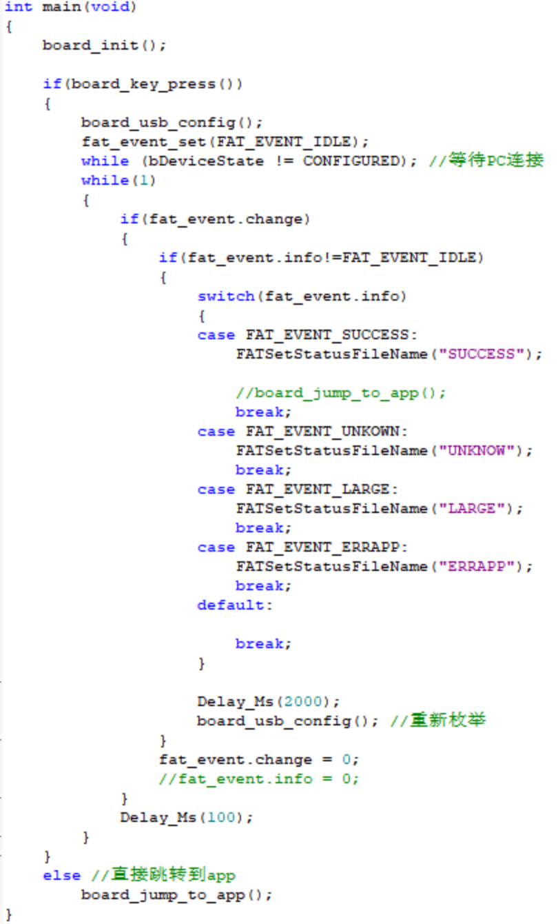
2.4.2 Bootloader Code
The bootloader side code is mainly used for firmware upgrades. When the mini power supply is connected to the computer via USB and the corresponding button is detected as pressed, the upgrade stage begins. The code creates a FAT16 file system and simulates a USB flash drive using the chip's internal Flash (starting from 0x08004000) for storage. The firmware to be upgraded can then be dragged and dropped into the USB flash drive, and the firmware will be copied to the chip's internal Flash. After completion, the power supply is restarted. If no corresponding button is detected after power-on, the process jumps directly to the App application code and executes it. The Main function code is shown in the figure below.
3. Assembly
: Assembly is relatively simple; this section only describes CNC structure assembly. First, connect the two PCBs. Place two button caps inside the middle frame, then place the PCBs into their corresponding positions on the middle frame. Apply thermal paste to the MOSFETs on the back of the power board, and then cover with the base plate and secure with screws. Note that the leads of the through-hole components on the back of the power board need to be flattened to prevent short circuits from contacting the casing.

4. Functions [See video link for details]
4.1 The CC meter
is connected to the circuit via two Type-C ports to detect voltage, current, power, etc. It can display waveforms, supports PD protocol detection, and has adjustable PPS output.
4.2 Buck-boost output :
Supports multiple power supply connection methods. The input voltage range supports 5-32V and has reverse connection protection. The XT30 interface outputs an adjustable voltage of 0.4-35V and an output current of 0-5A.
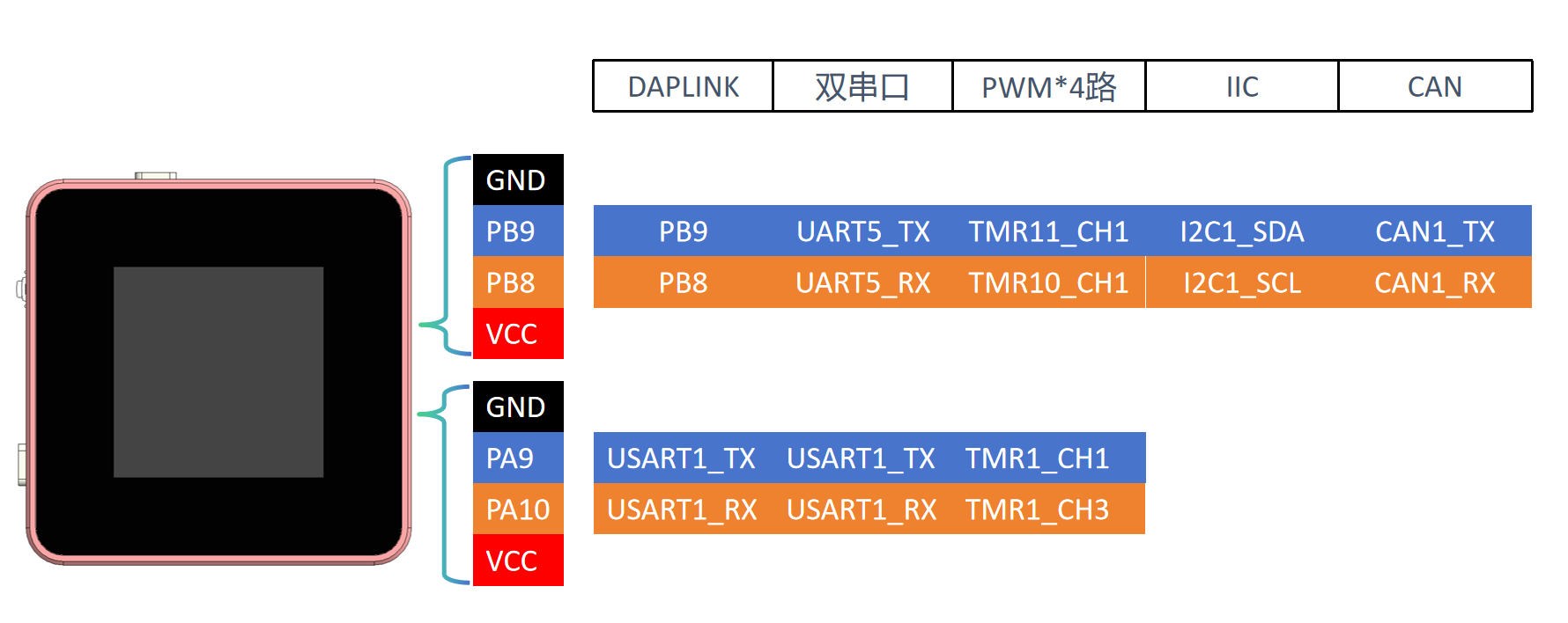
4.3 I/O expansion functions:
Expandable functions are achieved through the USB port and two 4-pin terminals, such as DAPLINK, dual serial ports, etc. The interface will display the relevant configuration data.
5. Usage and Testing
5.1 Usage Introduction
After PCB assembly, the firmware is first burned in. Currently, it is burned in using a J-Link or similar program via the reserved SWD port on the core board. After burning, connect to the PC via USB and update the calibration parameters using the host computer (downloadable in the attachment). Generally, you need to manually recalibrate the input voltage and current, output voltage and current, and the corresponding voltage of the output PWM.
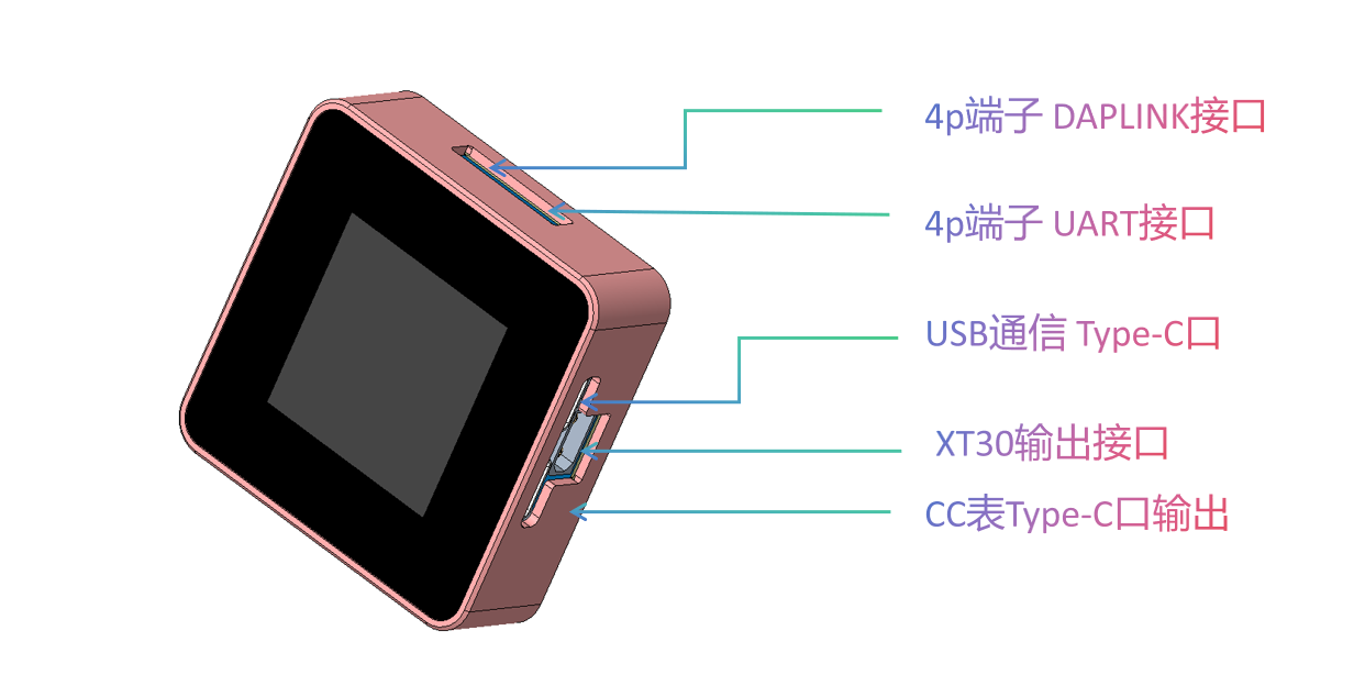
The power supply has 3 Type-C ports and 1 XT3.0 port, 2 buttons, and 1 pulsator switch. Their uses are shown in the diagram below. Currently, the focus is on simplifying operation as much as possible for the CNC power supply function; button functions may be modified as more functions are added later.
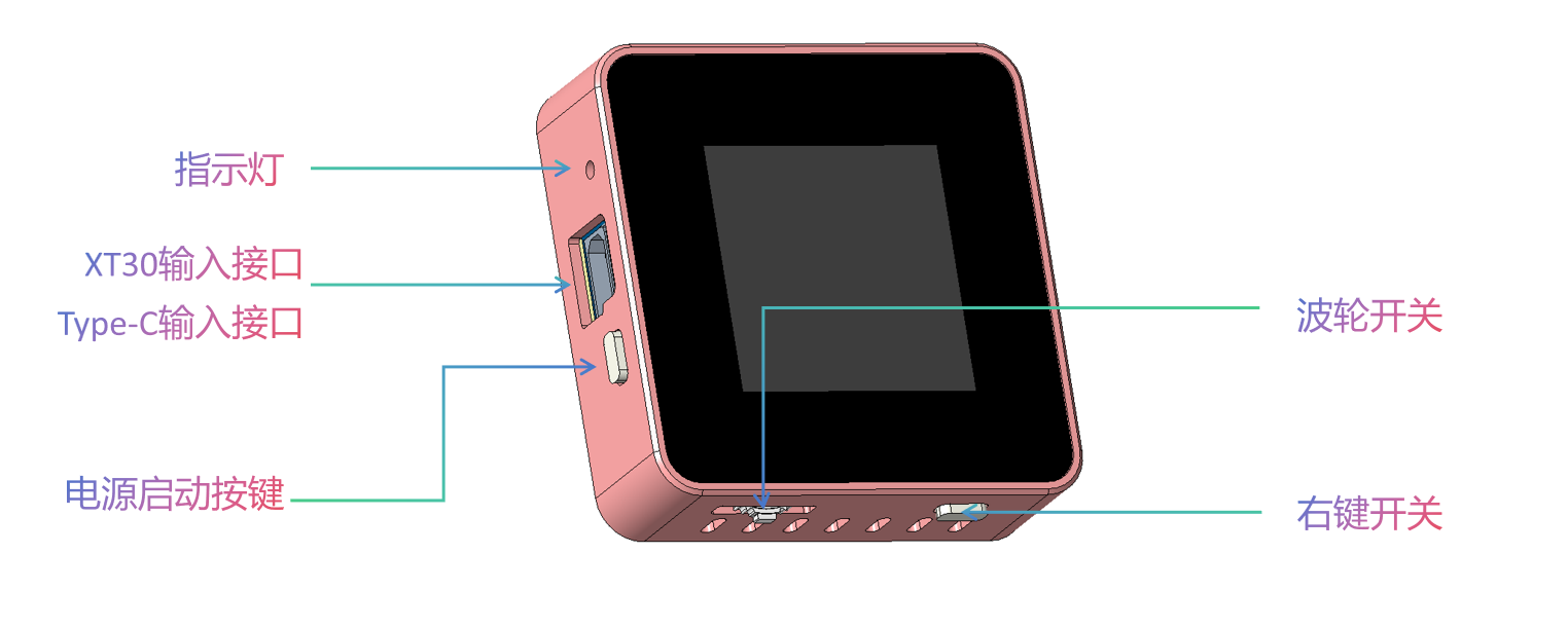
USB Communication Port: Used to connect to a PC to upgrade application firmware and as a separate power supply for the ammeter timing to eliminate internal loss errors. Also used to connect to the host computer software.
Power Input Port: Connects to a 5-32V power supply. Various charging heads can be connected via the Type-C port, or other power supplies can be connected from the XT30. The maximum power setting is selected by default via the PD protocol.
Indicator Lights: Dual-color indicator lights. Blue indicates the breathing light mode is running, which may be used for status indication later. Red indicates DAPLINK connection to a device.
Ammeter Function Output: Directly connected to the power input port, used as an ammeter for timing. Note that the voltage at this port also increases after the input power is boosted via the PD protocol! Caution is required when using external power supplies!
CNC Power Output: 0.4-35V output, XT3.0 interface. Note the positive and negative directions!
Rotary Switch: Switches between menus, focuses controls, and modifies parameters.
Right Function Key: Short press to switch interfaces in the current application; long press to return to the main menu.
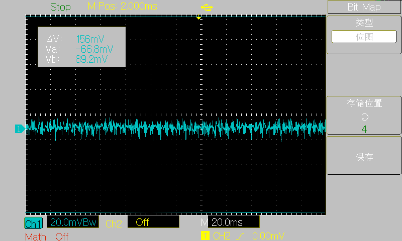
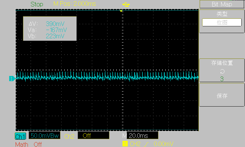
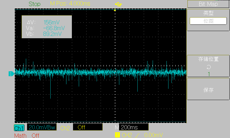
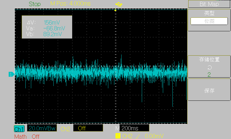
5.2 Load Ripple [Version 2.0, Version 3.0 not thoroughly measured]
Waveforms at various load stages. Due to the maximum power of the input power supply being 60W (20V 3A), the maximum output was only measured at 30V 2A.
[5V no-load]
[30V no-load]

[3.3V 3A]
[5V 3A]
[15V 3A]
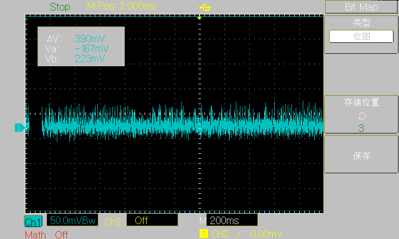
[30V 2A] The project
references
some code from the following authors. I greatly admire their open-source spirit and am very grateful to them!
Hezhou Official Repository: https://gitee.com/openLuat/luatos-soc-air32f103
STM32 USB Flash Drive Upgrade Firmware: https://gitee.com/joeylolipop/stm32-iap-msd
FUSB302 PD Protocol: https://gitee.com/liuzewen/PD_Micro
Cherry USB: https://github.com/cherry-embedded/CherryUSB/
Cherry DAP : https://github.com/cherry-embedded/CherryDAP/
Cherry RB: https://github.com/cherry-embedded/CherryRB
LCSC DAPLINK Debugging Tool: https://oshwhub.com/li-chuang-kai-fa-ban/li-chuang-daplink-diao-shi-gong-ju
Other
main code is still being organized and will be submitted to Gitee later.
Open Source Code: https://gitee.com/yllff/flpower
QQ Discussion Group: 334607120
Important!
1. When prototyping, select 1.0mm thickness for both PCBs! 1.0mm thickness! 1.0mm thickness!
2. The component parameters in the schematic have been basically checked, but it's best to double-check them when generating the list.
4. The V3 version's main controller is AT32F403AGT7!
5. All parts (casing, front panel, PCB) have been modified in the V3 version, please note!
6. U21 and U22 on the core board and U21 on the power board are not feedthrough capacitors, they are used for shorting!! Some replica makers have already fallen into this trap!!!


 京公网安备 11010802033920号

 146-93-318-41-036


