Let's take another look at the pictures of the ESP32S2-Mini Kalimba 17-key music keyboard, especially
the back.
This is a replication project. I recently needed a USB-A network card, so I replaced the port based on Kirito's project. I widened the PCB to make soldering easier, and I might add a casing later
(turning the USB3/2 port into a 10M/100M/000M Ethernet port module).
Implemented based on the RTL8153B, it supports 10M/100M/1000M networks and primarily supports USB 2.0/USB 3.0-A ports.
For personal use, the cost of a single module is approximately 30 RMB.
It will generate some heat when running at full speed, but it's still within acceptable limits.
The board outline CAD file is uploaded; other interfaces (Type-C, etc.) can be replaced based on this.

Instructions/Tutorials:
1. This is a pure hardware module and does not require programming. If your computer doesn't respond or your device manager shows drivers with exclamation marks, please download the attached driver and install the corresponding driver for your system.
2. Regarding the solution for a MAC address of 0: (Actually, MAC address 0 can still be used) Use the attached tool, realtek_usb_lan_tool. Open it, plug it in, and it will automatically recognize the network card. After recognition, set the MAC address, and select EFUSE for model select. Note that EFUSE can only be modified once, so please modify it carefully! See the attached document for detailed instructions on using the tool; there are many references available, so I won't go into detail here.
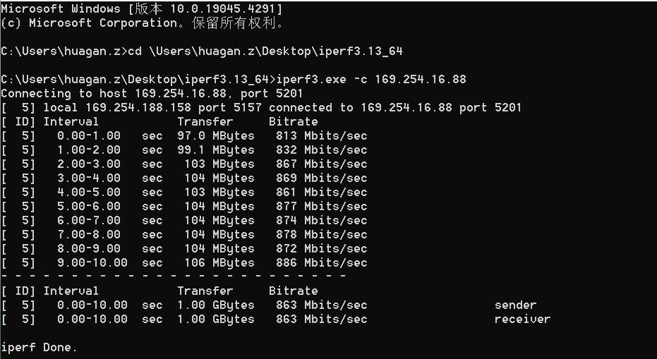
Testing status:
![]()
Tested using iperf.
realtek_usb_lan_tool.zip
Install_USB_Win11_11.0.2.1_20_08162021.zip
iperf-3.17.1-win64.zip
M.dxf
PDF_USB3.0-A Port Gigabit Ethernet Adapter.zip
Altium_USB3.0-A Port Gigabit Ethernet Adapter.zip
PADS_USB3.0-A Port Gigabit Ethernet Adapter.zip
BOM_USB3.0-A port gigabit network adapter.xlsx
93672
Type-C debug serial port separation module
Decoupling of debug serial ports for integrating some development boards into Type-C interface A8/B8 (SBU1/SBU2)
I recently worked on a small gateway project and got my hands on an RK3528 development board. I discovered this rather elegant debug serial port design: connecting the RX and TX pins to two SBU lines (A8 and B8) that are rarely used on the Type-C interface.

The SBU lines are typically used as AUX_P/AUX_N differential lines in the DP protocol when DisplayPort (DP) is enabled. On today's development boards, the PD/QC power-on and USB HOST/OTG interfaces on Type-C rarely use the SBU lines. Since QC power-on and USB functionality require DP/DM, a 16-pin Type-C female connector is commonly used.
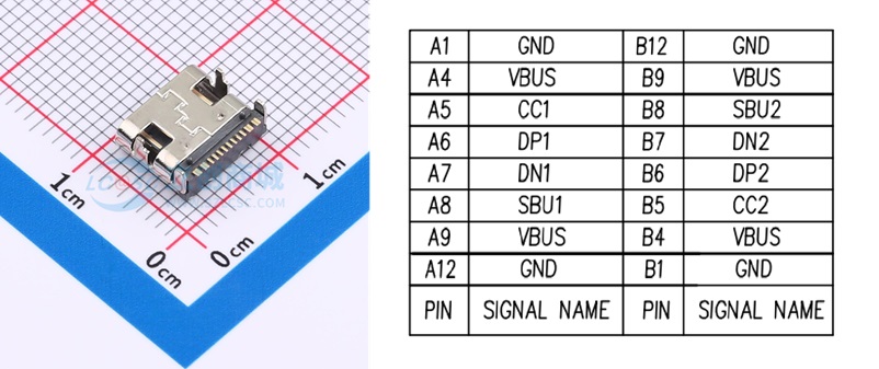
The 16-pin Type-C female connector comes with SBU1 and SBU2, but they are usually unused. Perfectly, the RX and TX pins for the debug serial port can be used for them.
However, most common serial port tools on the market are unlikely to have this connection method. Connecting it to a Type-C test board, not to mention the unequal differential lengths, is ugly and inelegant!
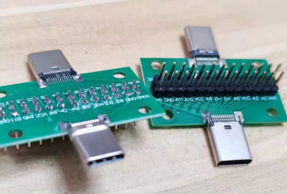
So, I've created an elegant little accessory to complement this elegant design. This design includes both 16-pin and 24-pin female connectors (I personally think the 24-pin version is unlikely to be used and is more difficult to solder). All connectors are from the Soho brand (a 16-pin minus 15-pin option). With a cheap MX1.25-3P to DuPont adapter cable, it can connect to most TTL serial port tools on the market.
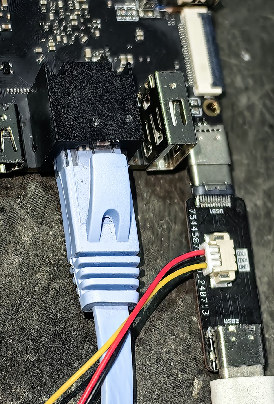
Note: If communication fails, the TX/RX lines may not be crossed; simply flip the Type-C cable.
The small components are relatively simple. Since there are no chips, there is no firmware, and compatibility issues are unlikely.
Except for the two SBU lines, all others are straight-through. If used for power supply, pay attention to the current!
PDF_Type-C Debug Serial Port Separation Module.zip
Altium_Type-C Debug Serial Port Separation Module.zip
PADS_Type-C Debug Serial Port Separation Module.zip
BOM_Type-C Debug Serial Port Separation Module.xlsx
93673
Four-channel power output module based on LM2596S
A four-channel power supply module based on the LM2596 series chip. It includes diode reverse polarity protection and fuse short-circuit protection.
LM2596 Series Chip Overview: Type: It is a buck switching regulator. Input Voltage: The LM2596 series can generally accept input voltages up to 40 volts. Output Voltage: Fixed output versions are available in 3.3V, 5V, and 12V, and adjustable versions are also available, where the output voltage can be set by connecting two external resistors. Output Current: Capable of providing a maximum output current of 3A. Efficiency: High-efficiency conversion, typically achieving 81%-88% efficiency under full load conditions. Protection Functions: Equipped with overheat and overcurrent protection functions to improve system reliability. Package: Typically uses a TO-220 package for easy heat dissipation.
I. Introduction to DC-DC Power Converters
A DC-DC power converter, or DC-DC converter for short, is an electronic device that can convert one DC voltage to another. Its main function is to achieve voltage boosting or bucking while ensuring power transmission efficiency to meet the power supply needs of different electronic components.
II. Principle of DC-DC Power Converters
The working principle of a DC-DC converter is based on switching mode. The following are its core components and basic workflow:
1. Switching Element
: The switching element, typically a field-effect transistor (MOSFET), is the core of the DC-DC converter. It converts the input DC current into a high-frequency pulse signal through rapid switching.
2. Energy Conversion and Storage
: Inductor: When the switching element is on, the inductor stores energy; when the switching element is off, the inductor releases energy.
Capacitor: Used to smooth the pulse signal released by the inductor, providing a stable DC output.
3. Control Circuit: The
control circuit monitors the output voltage in real time through a closed-loop feedback mechanism and adjusts the switching frequency and duty cycle of the switching element to maintain a constant output voltage.
III. Types of DC-DC Power Converters
Based on voltage conversion requirements, DC-DC converters mainly come in the following types:
1. Boost Converter: A
boost converter can convert a low input voltage into a higher output voltage. It is suitable for applications requiring high voltage power supply, such as LED drivers and solar power generation.
2. Buck Converter: A buck
converter reduces the input high voltage to the required low voltage level. It is widely used in power management of portable electronic devices such as mobile phones and computers.
3. Buck-Boost Converter:
A buck-boost converter can increase or decrease the input voltage as needed. Suitable for battery chargers, portable devices, etc.
IV. Features of DC-DC Power Converters
1. High Efficiency:
The high efficiency of DC-DC converters is a significant feature, generally above 80%, with high-performance products reaching over 95%.
2. Miniaturization:
Increased switching frequency allows for smaller inductors and capacitors, facilitating device integration.
3. Stability
: Closed-loop feedback control ensures the stability of the output voltage, unaffected by input voltage fluctuations and load changes.
4. Protection Functions:
DC-DC converters typically have overvoltage, overcurrent, short-circuit, and overheat protection functions, improving system reliability.
This circuit connects four different versions of the LM2596S chip in parallel and provides corresponding DuPont wire interfaces and lead-in terminals for easy connection to various devices. The adjustable

3.3V,
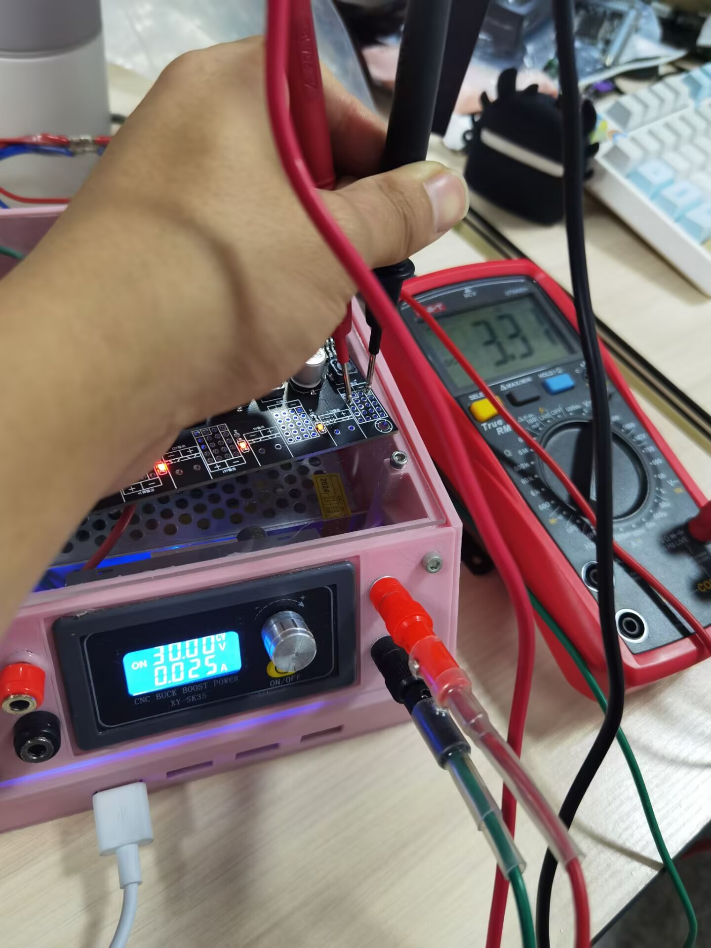
5V, and
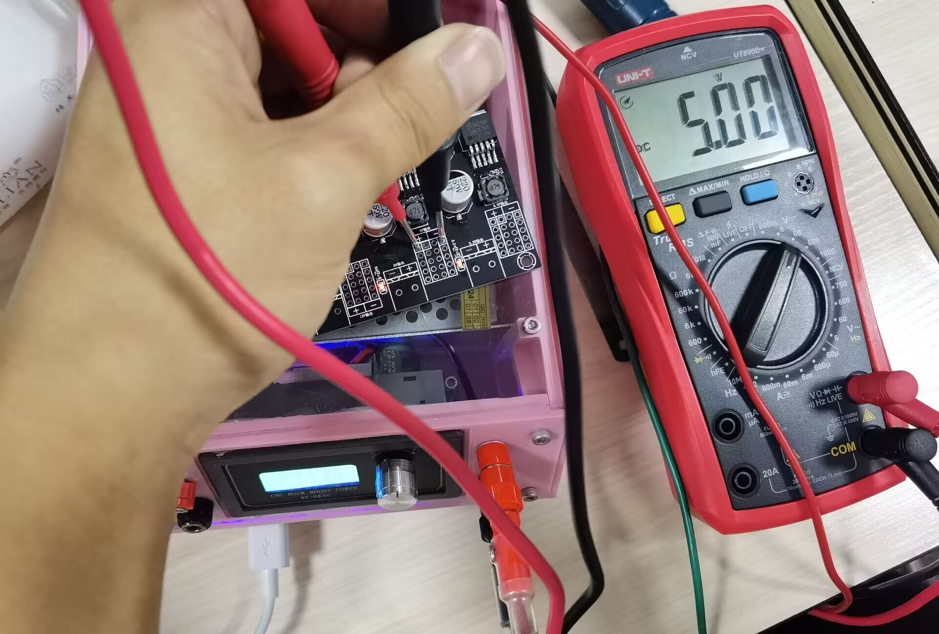
12V output
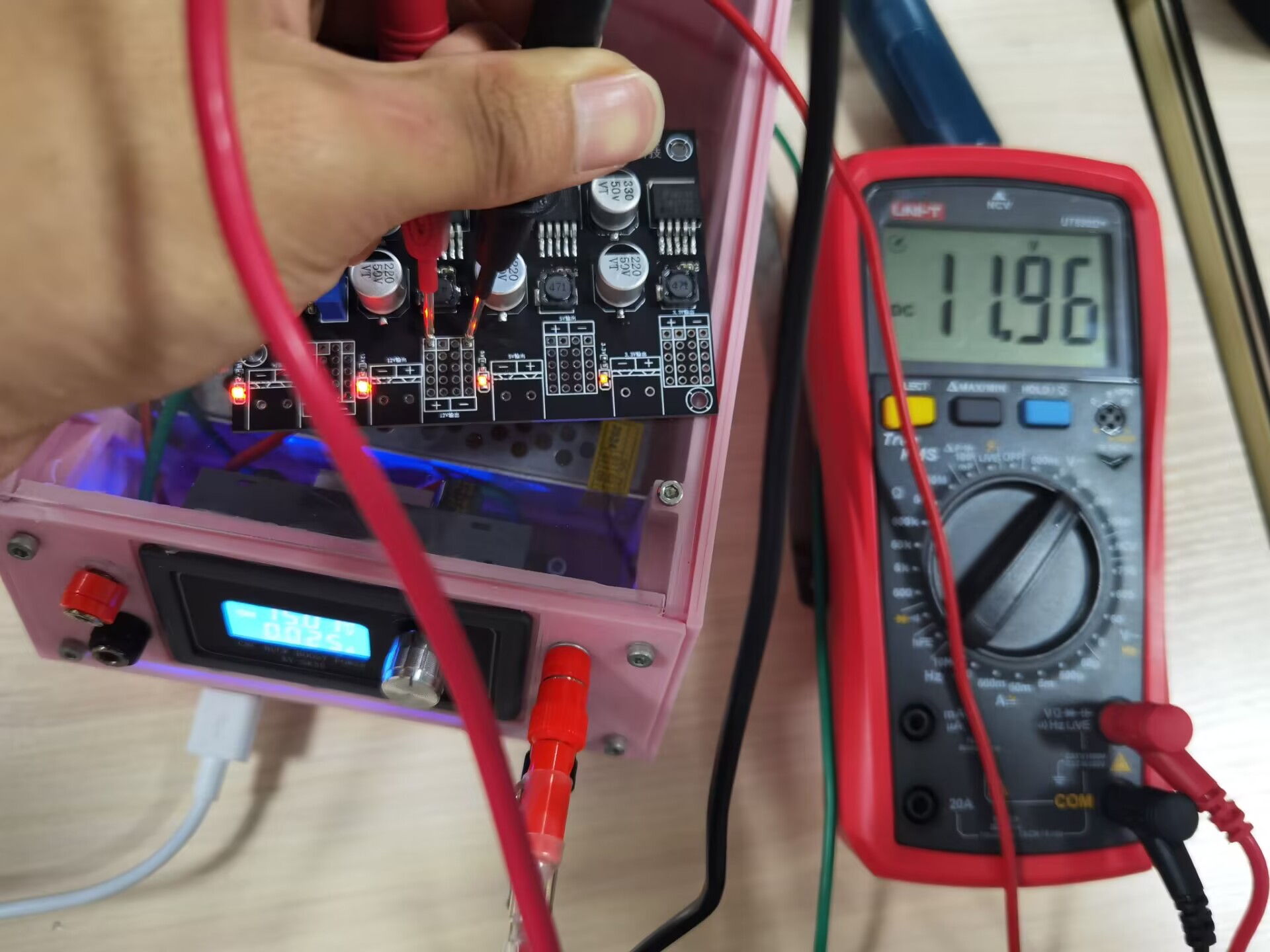
versions
were not tested due to the lack of high-power loads.
PDF_LM2596S-based four-channel power output module.zip
Altium LM2596S-based quad power output module.zip
PADS LM2596S-based Quad Power Output Module.zip
BOM_Four-channel power output module based on LM2596S.xlsx
93674
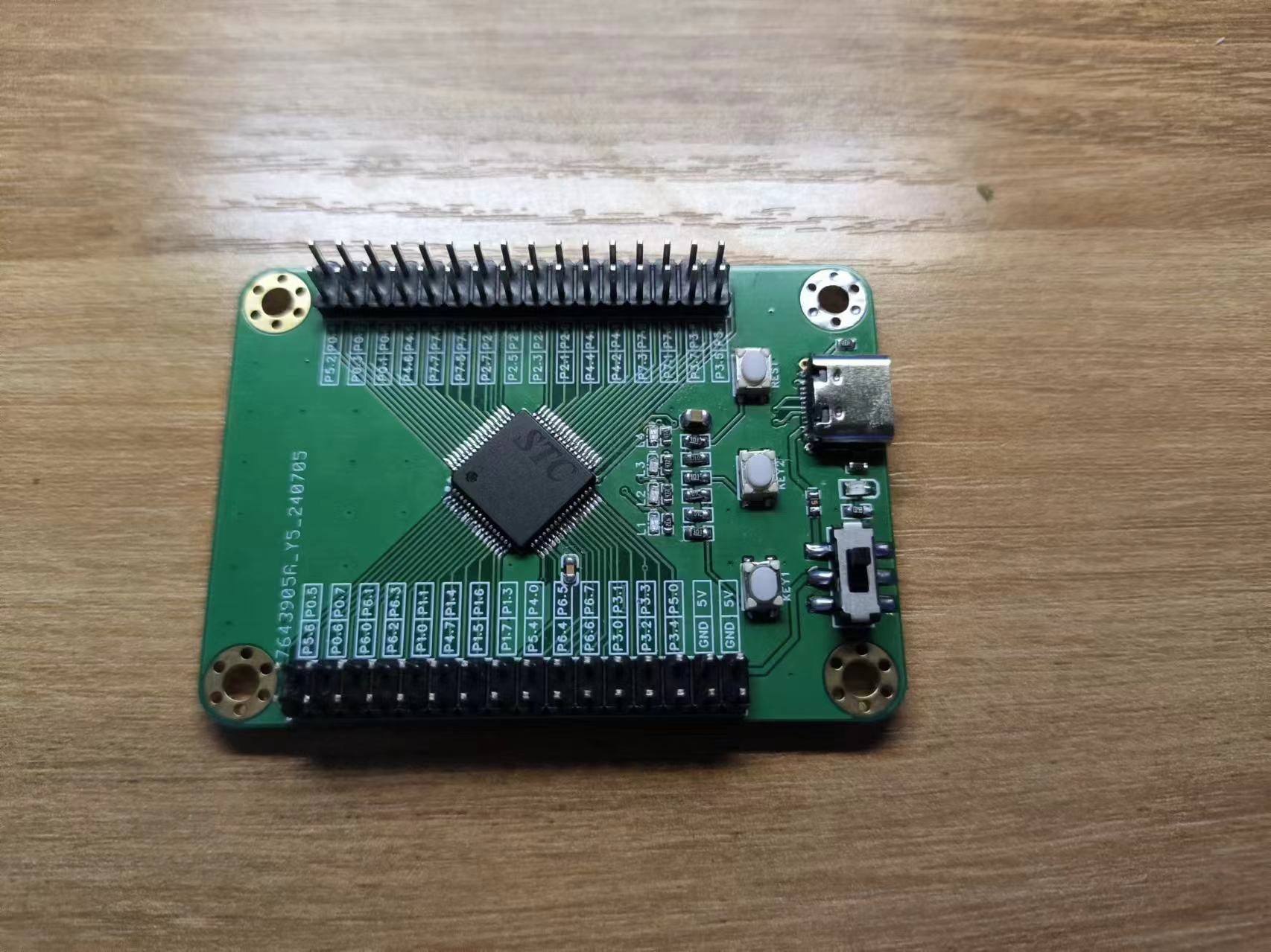
STC Core Board
STC Core Board (STC32G12K128) - Verified
Note the flash package size; it should be the same as the CH340N.
WeChat_20240719013738.mp4
8-digit LED running light - forward and reverse reciprocating flow - array method.zip
PDF_STC Core Board.zip
Altium_STC core board.zip
PADS_STC core board.zip
BOM_STC Core Board.xlsx
93675
JLink v9_typeC_noScrew_ verified
JLink v9_typeC_noScrew_ verified
1. Uses a Type-C interface, STM32F205 main controller, supports JTAG and SWO output. Firmware updated to 9.4 without issues, personally tested. All components used in this project are readily available. If a more suitable component is needed, the ESD protection circuit can be replaced with an ESD5302F.
2. D2 is the SWD write protection circuit; if unavailable, it does not need to be soldered.
PDF_jlink v9_typeC_noScrew_verified.zip
Altium_jlink v9_typeC_noScrew_verified.zip
PADS_jlink v9_typeC_noScrew_verified.zip
BOM_jlink v9_typeC_noScrew_verified.xlsx
93677
DS3231 Real-Time Clock (RTC) Module with EEPROM
A DS3231 module that isn't perfect, but still delivers decent results.
Back in 2022, I actually built a DS3231 board. My soldering skills weren't great then, so I used a lot of through-hole components;
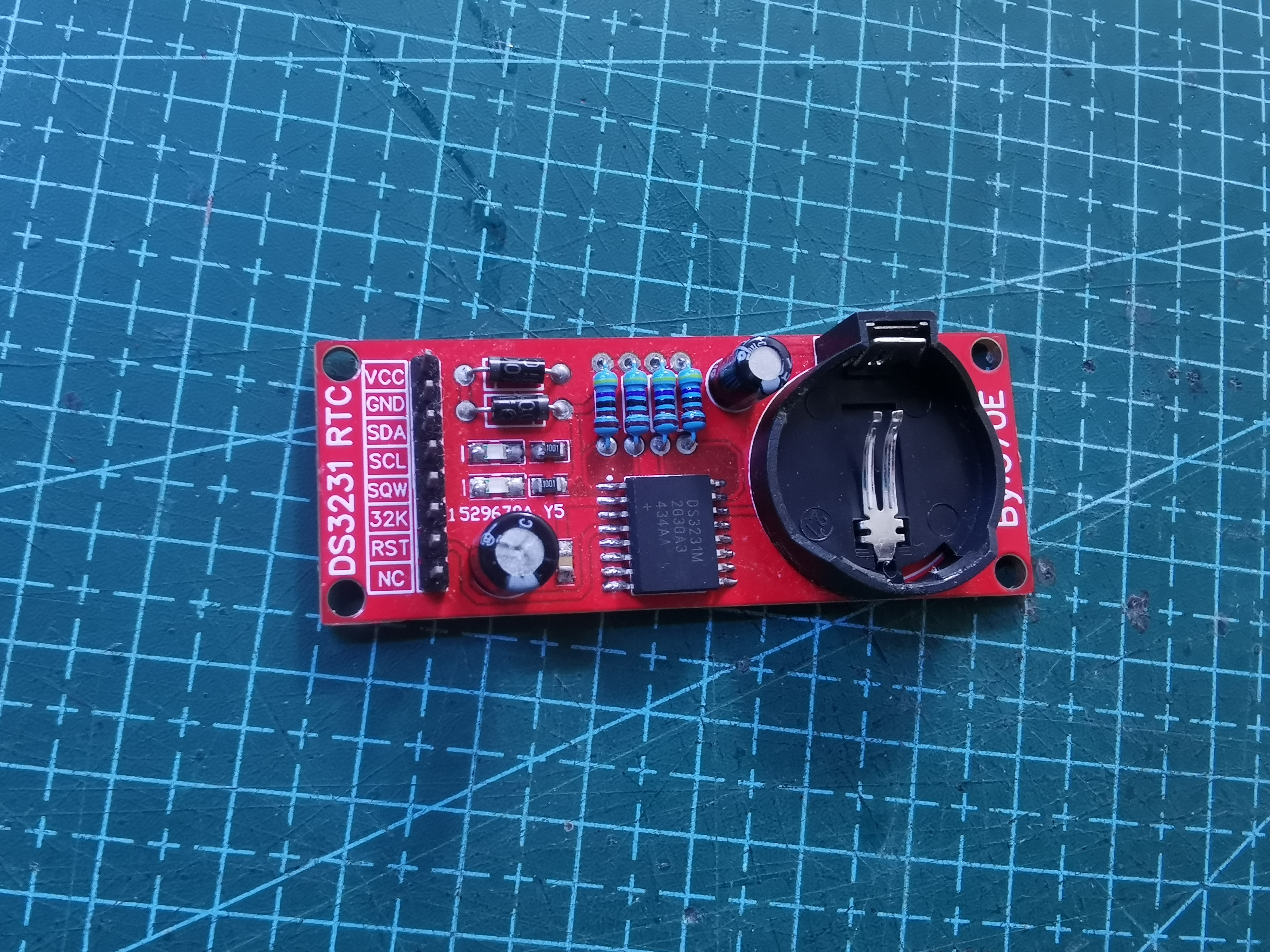
Figure 1 shows the DS3231 module drawn in 2022.
Two years later, in 2024, my soldering skills were barely passable, and I happened to have some stock available at the end of June, so I started this project. The board's dimensions are 50x25mm. The backup battery uses the most common CR2032 battery on the market. It's not too small, but it's not too big either; it can be used on breadboards, perforated boards, or directly connected via jumpers. The circuit diagram is very simple. An AT24C02 memory is added to the IIC bus to store some operational information. To prevent address conflicts with other EEPROMs, R6, R7, and R8 are shorting blocks used to change its communication address. Please pull them high or low as needed. Later, I plan to see if I can use it to make a custom time switch.
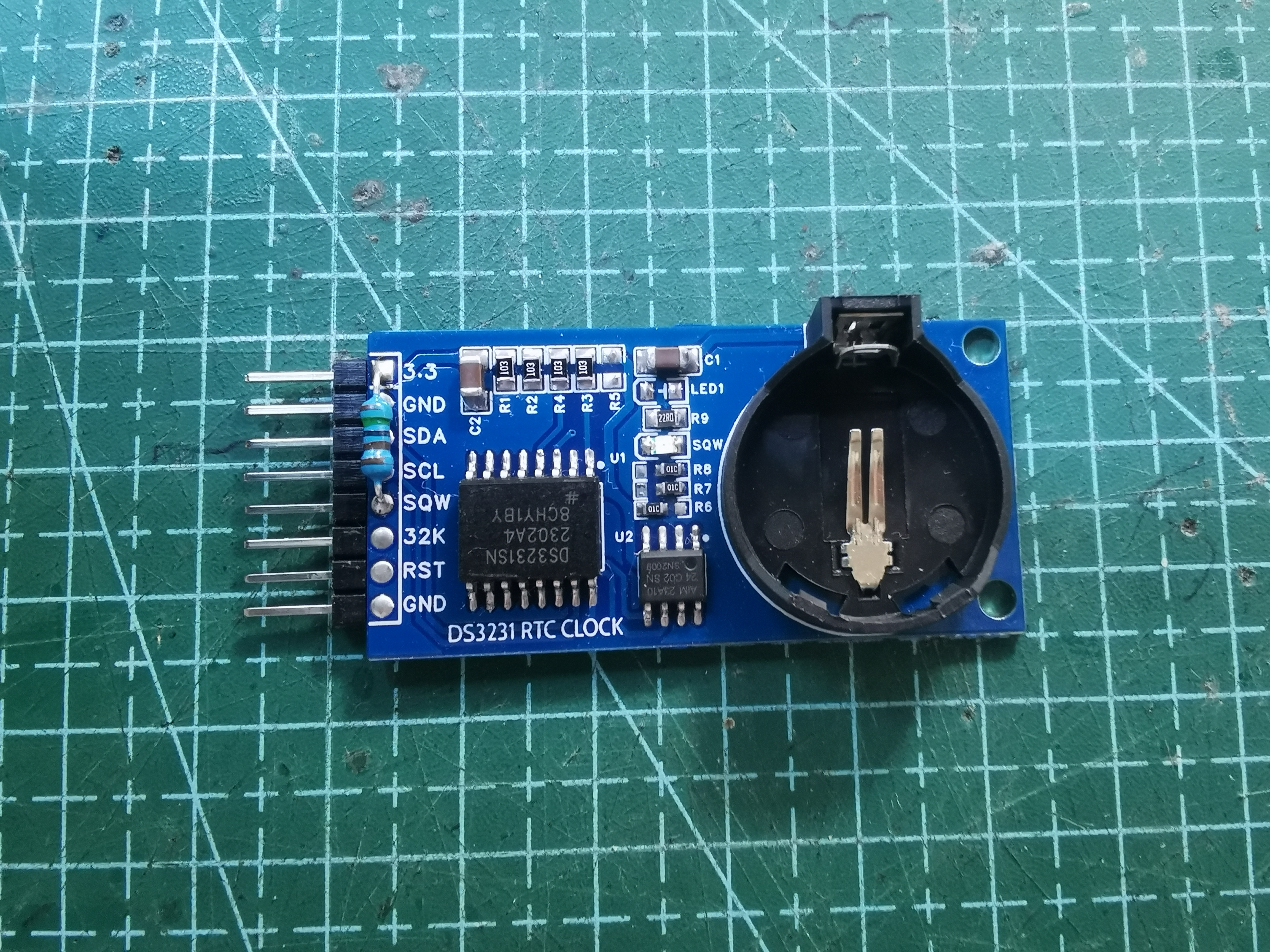
Figure 2. The second DS3231 module I drew in 2024.
I included several programs for this module, including a program to measure the address of IIC devices to determine the addresses of all devices on the current IIC bus, and an Arduino library file for DS3231 read/write that I wrote in 2022. Since I am using an STM32duino, you need to set the IIC bus to pins PB6 and PB7 for testing. Two more points to note: the DS3231 should not be powered by more than 3.3V, as this may cause it to burn out. Also, my board's SQW pin is not pulled up. If you need to use SQW to light up the LED, you need to add an external pull-up resistor and reduce the resistance of R9 (you can see that I added a resistor on my board, from 3.3V to SQW. This way, the SQW pin can drive the LED).
The following is a program introduction:
1. Why did I write this library: Actually, in the video I introduced about the DS1307, the author wrote a library file for the DS3231. Originally, I also wanted to utilize this feature, but it has two serious problems. First, it returns a string value, while sometimes we need to compare times, splitting the string and converting it to a number. This requires code, which is inconvenient. Furthermore, the way foreigners set the time and format is different from Chinese habits, making it easy to make mistakes; I frequently set the time incorrectly myself. The second problem is more critical: I use STM32duino a lot, and these boards throw errors when using libraries written by foreigners, making this RTC unusable on STM32F. Actually, my main goal is to learn how to write libraries, as it greatly simplifies my code and is an important way to understand Arduino. Contributing to others is also a reason; I've always used open-source libraries for free, so I should contribute my own library so everyone can use them too! Therefore, I decided to write this library myself to gain a fresh understanding of this chip.
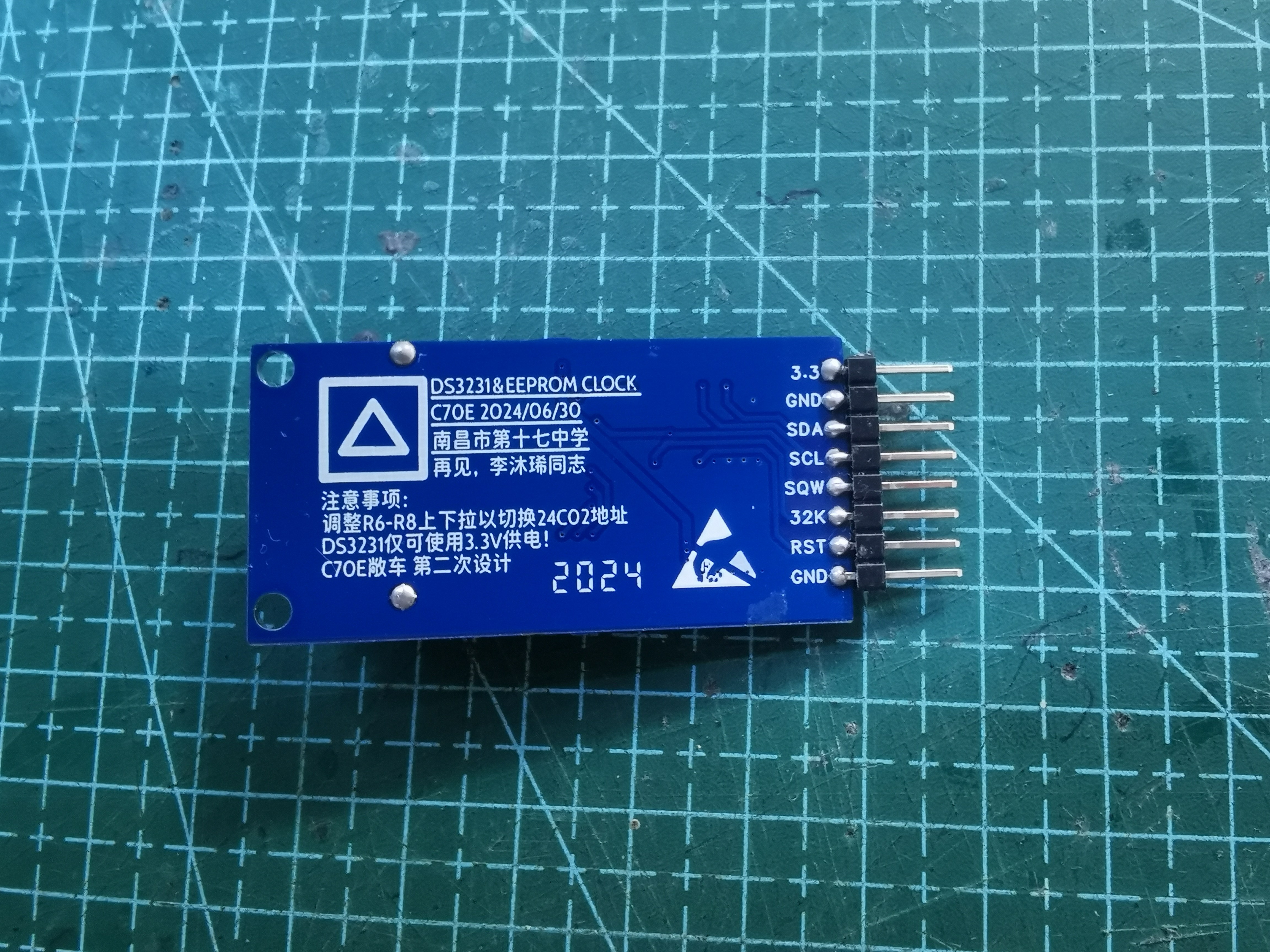
Figure 3. Back of the module
. 2. Executable commands in this library file:
Write time ds3231.SetTime1(a,b,c); This command is responsible for writing the set time into the DS3231 register area; a, b, and c are integer variables, corresponding to hours, minutes, and seconds respectively.
Write time ds3231.SetTime2(d,e,f,g); This command is responsible for writing the set time into the DS3231 register area; d, e, f, and g are integer variables, corresponding to year, month, day, and week respectively;
Write SQW frequency blink ds3231.sqw(h); This command is responsible for setting the DS3231 SQW pin to output a frequency pulse. When h=0, no output is performed; when h=1, a 1Hz pulse is output. Other frequency pulses are not performed, and in fact, other frequency pulses are not used.
Read time ds3231.YEAR(); This command reads the year from the internal register area of the DS3231, an integer variable.
`ds3231.MOUNTH()` reads the month (integer variable) from the internal register of the DS3231.
`ds3231.DATE()` reads the day (integer variable) from the internal register of the DS3231.
`ds3231.WEEK()` reads the week (integer variable) from the internal register of the DS3231.
`ds3231.HOUR()` reads the hour (integer variable) from the internal register of the DS3231.
`ds3231.MIN()` reads the minute (integer variable) from the internal register of the DS3231.
`ds3231.SEC()` reads the second (integer variable) from the internal register of the DS3231.
Read the temperature using `ds3231.temp()`; this command reads the temperature from the internal register of the DS3231, a floating-point variable.
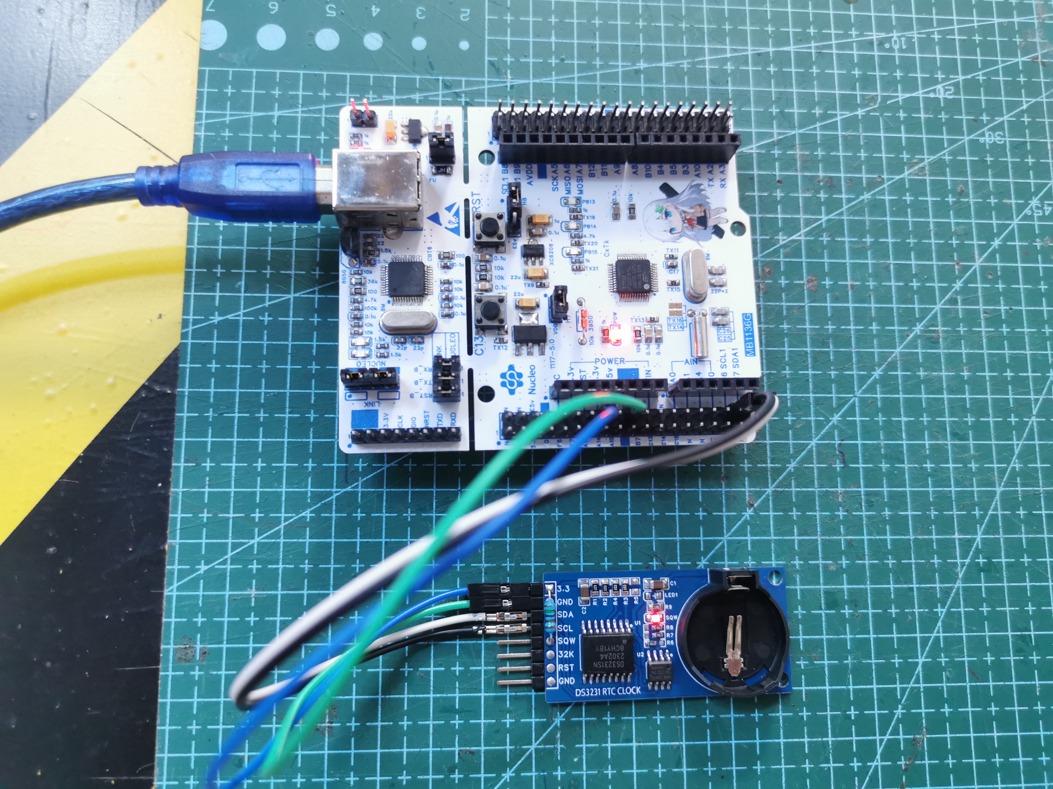
Figure 4. The module is being tested on a self-made Nucleo-48 Kawasaki mirror.
3. This library is based on the Wire library and requires the Wire library to be used. However, the Wire library is usually included with the Arduino IDE. Compatibility has been tested with STM32duino, ATMEGA8A series, and ordinary Arduino, and all can operate normally.
Test method: Burn the demo in the attachment to the MCU. After opening the serial port assistant, you will receive the following message, indicating a successful test.
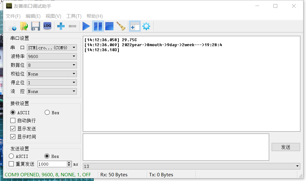
Figure 5. Message returned by the MCU to the serial port assistant (temperature/year/month/day/hour/minute/second).
I'm going to participate in the CW32 training camp later. I hope the project in the training camp will be successful on the first try! See you in the next open-source project! Thank you for watching.
[Project Files] DS3231 RTC Module.zip
[Schematic Diagram] DS3231 Real-Time Clock (RTC) Module.pdf
[BOM] DS3231 Real-Time Clock (RTC) Module.xlsx
[PCB Design Files] DS3231 & EEPROM Clock 2.0.zip
[Test Program] IIC Bus Mounted Device Address Lookup.zip
[Test Program] DS3231 Clock Example.zip
[Library Files] DS3231 Clock Library Files.zip
PDF_DS3231 Real-Time Clock (RTC) Module with EEPROM.zip
Altium DS3231 Real-Time Clock (RTC) Module with EEPROM.zip
PADS_DS3231 Real-Time Clock (RTC) Module with EEPROM.zip
BOM_DS3231 Real-Time Clock (RTC) Module with EEPROM.xlsx
93678
electronic
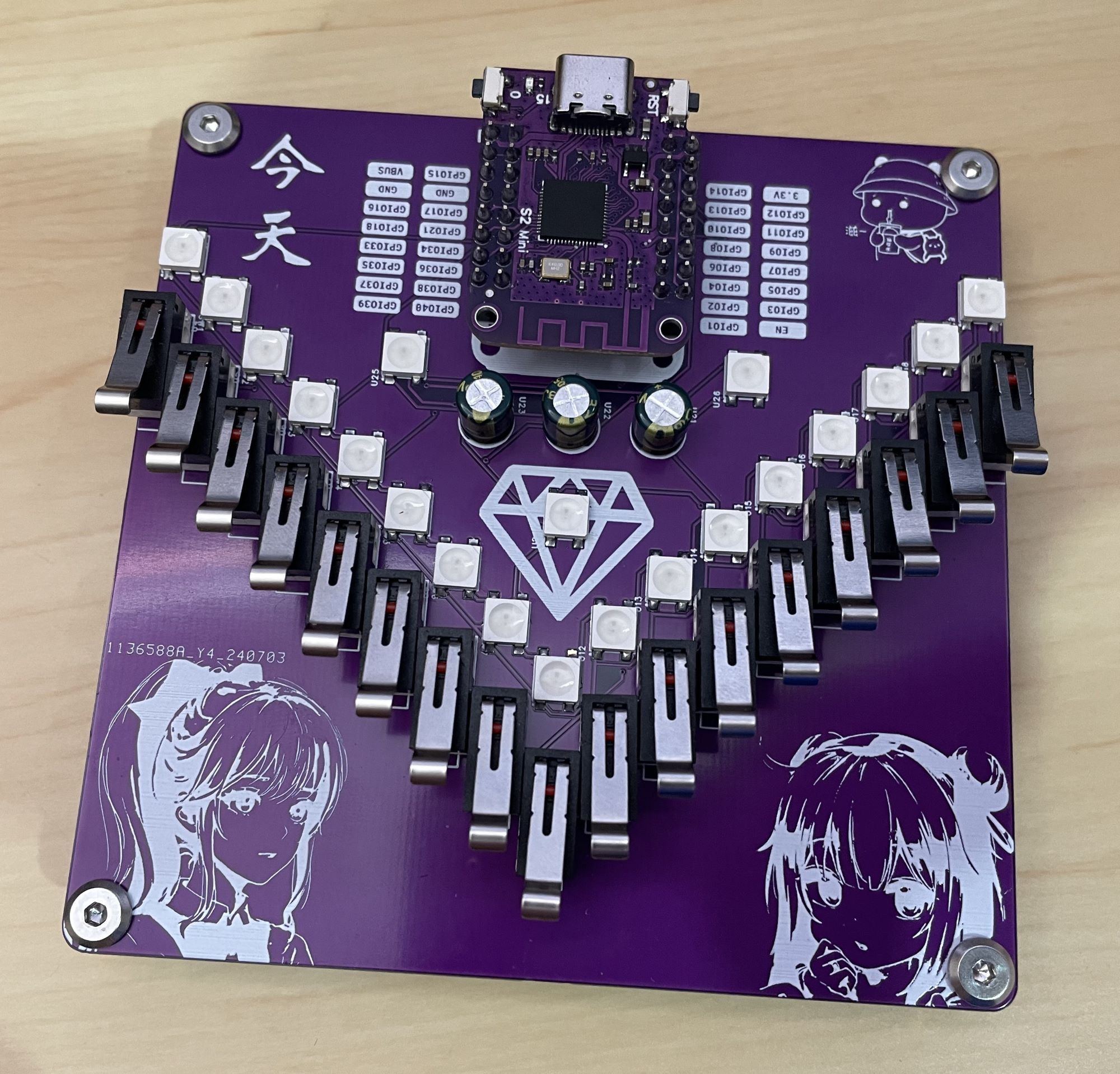 Let's take another look at the pictures of the ESP32S2-Mini Kalimba 17-key music keyboard, especially
  the back.
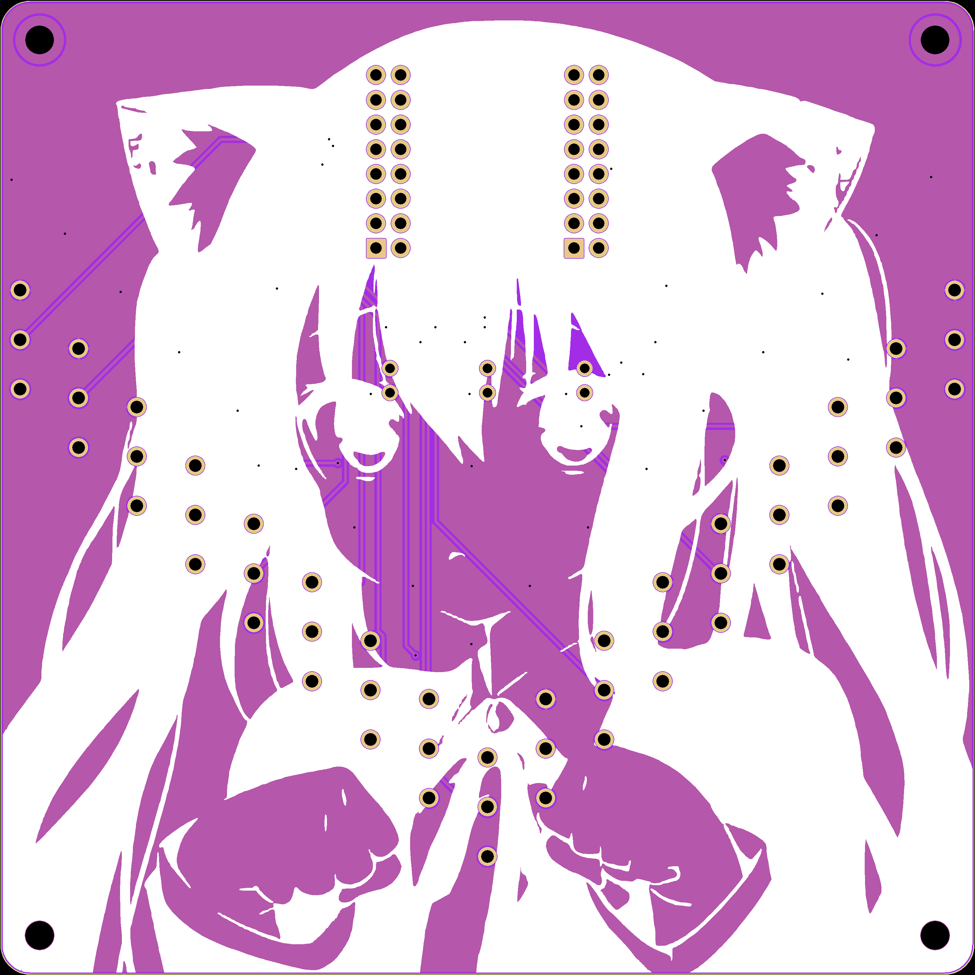


 京公网安备 11010802033920号

 ST93C57CM6013TR


