Last updated: August 25, 2024
Known Issues - Solutions:
Fuse easily blows and does not reset - Shorting the fuse pads
during the first programming session does not automatically enter download mode - Manually press boot to enter download mode. HXC Development Board Type A

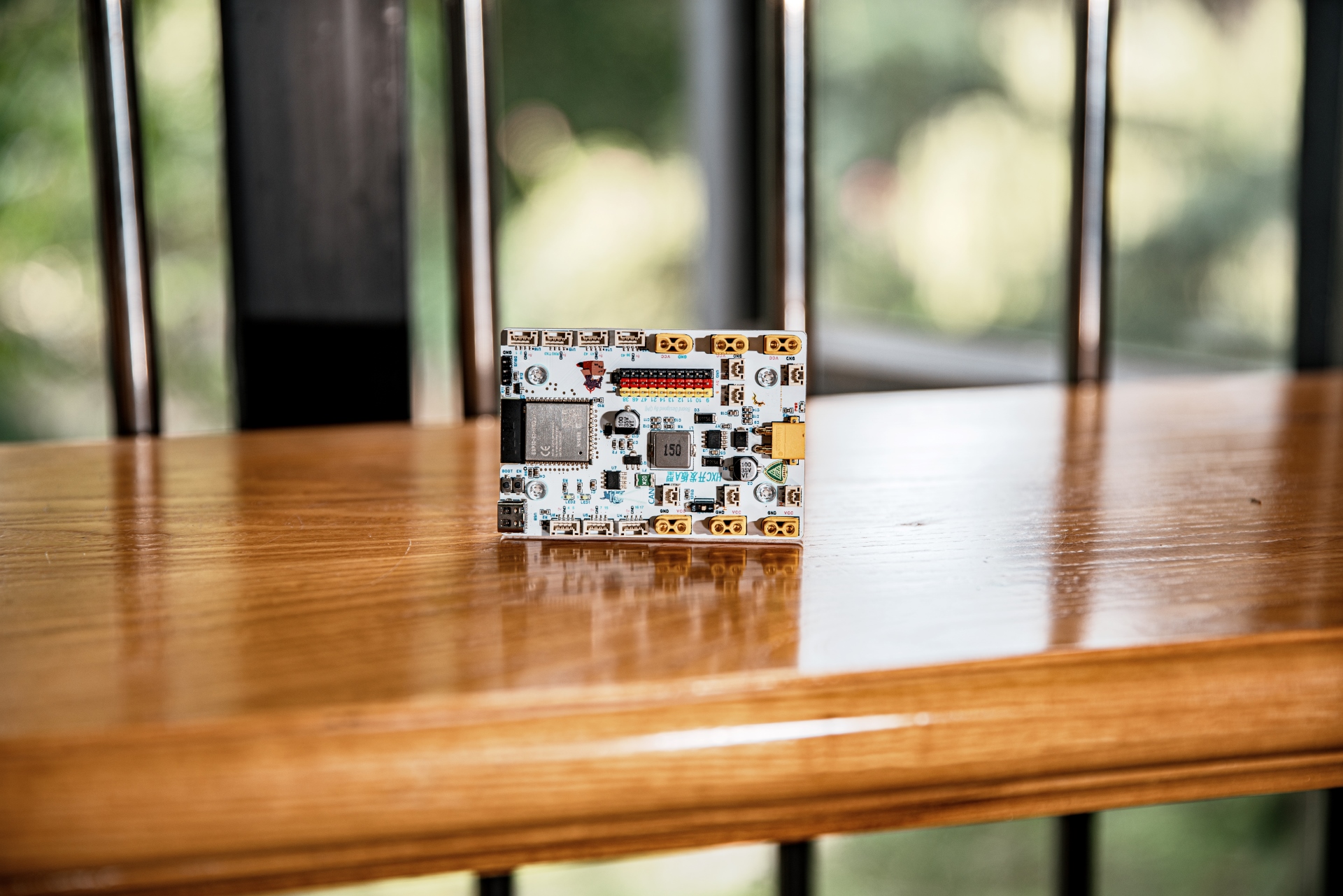


Design Concept:
Although the DJI Type A development board boasts powerful performance and has been validated in competitions for many years, its high price, difficulty in repair, high learning curve, and long development cycle have always troubled us.
Therefore, we designed this development board using the ESP32 S3 as the main controller and utilizing as many low-cost and common components as possible, keeping the cost below 50 yuan while achieving 80% of the functionality.
One CAN channel (with transceiver chip),
maximum 26V power input (can be powered by TB48S battery),
maximum 5V 3A step-down output,
seven GH1.25-4P customizable interface types (configurable as UART, I2C, etc.)
, ten GPIO pin headers for direct-plugging servos,
two programmable LEDs,
one SBUS/DBUS interface (receiver interface),
six XT30/CAN motor interfaces
, 5V and 3.3V motor interfaces with fuses and TVS protection.
All components are located on the front for easy soldering.
Hole positions and dimensions are completely consistent with DJI development board A type. Sample programs and code repositories:
All code is based on ESP32ArduinoSDK. Most libraries are developed in C++, and most modules are encapsulated in a single .hpp file for easy calling.
We use the vscode + platformio environment for development. If you prefer, you can also use the Arduino IDE or ESP-IDF. Simply copy the .hpp file of the required module to the project directory.
See the README file in the repository for details.
Click to enter the GitHub code repository .
Currently, our hardware libraries include:
DJI 3508, 2006 motor,
Zhang Datou closed-loop stepper control,
Huaner Bus servo,
OPS-9 odometer,
SBUS/DBUS.
Only 4 lines of code are needed to control M3508, M2006, GM6020.

Hardware Overview:
Peripherals:
4*SPI,
3*UART (USB can be simulated additionally)
, 2*I2C
, 2*I2S
, 8*PWM,
20*ADC.
All peripherals can be mapped to any available pin.
Power Supply:
VCC is stepped down to 5V via TPS5430. 5V is stepped down to 3.3V via AMS1117.

CAN:
Because the ESP32 has a built-in CAN controller, we only added an external TJA1050 CAN transceiver chip.

Download Circuit:
ESP32 The S3 has a built-in USB interface, so no additional download circuit is needed. This USB port can be configured as a serial port and for JTAG use.

Note that
during the first download, you need to press BOOT before inserting the USB to enter download mode.
After the program is downloaded, sometimes you need to restart the microcontroller for it to work properly (press EN).
The SBUS/DBUS
standard level inversion circuit uses the common S8050 transistor

test points ,
bringing out the test points for most pins, facilitating jumper wires, multimeter troubleshooting, and repair.

The HXC development board D-type
C3 minimum module has CAN transceiver and can be used as a main controller, CAN monitoring terminal, ESPnow receiver, etc., for functions such as
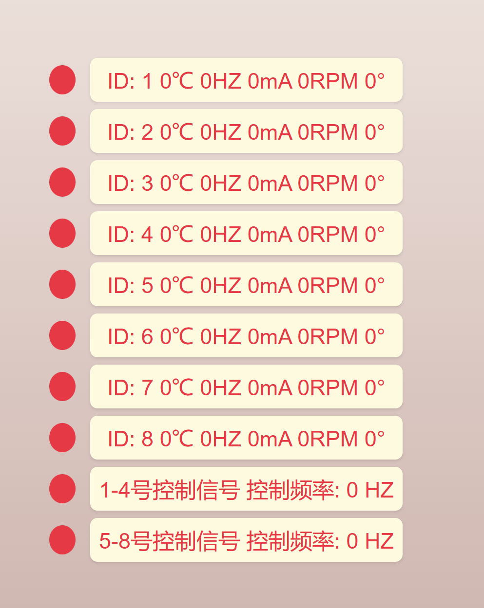
motor online detection ,
web-based online testing, and PID functionality. Once developed, it will be open-sourced.
The large power divider board
doesn't need much introduction;
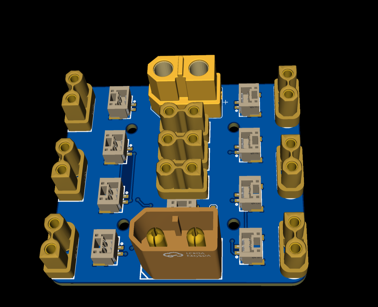
the small power divider board
is very compact.

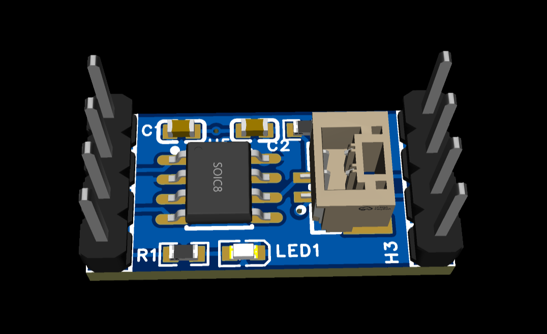
The CAN transceiver module
can be used with ordinary ESP32.
A-plate outer casing.stp
HXC Development Board Type A BOM.xlsx
PDF_ESP32 Development Board Kit.zip
Altium_ESP32 Development Board Kit.zip
PADS_ESP32 Development Board Kit.zip
BOM_ESP32 Development Board Kit.xlsx
92588
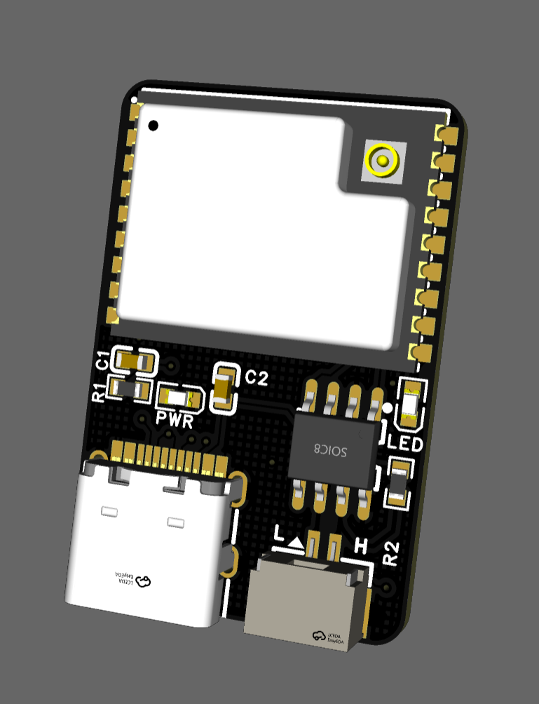
CH340N serial port (verified)
The CH340N is a small USB-to-TTL serial chip. I used the CH340N chip to build a USB-TTL serial communication module, realizing bidirectional communication between a USB interface and a TTL level device. This module is small in size and suitable for serial port debugging and microcontroller communication.
[d96b786361a2fcf4b5b3c7a5814a800.jpg]
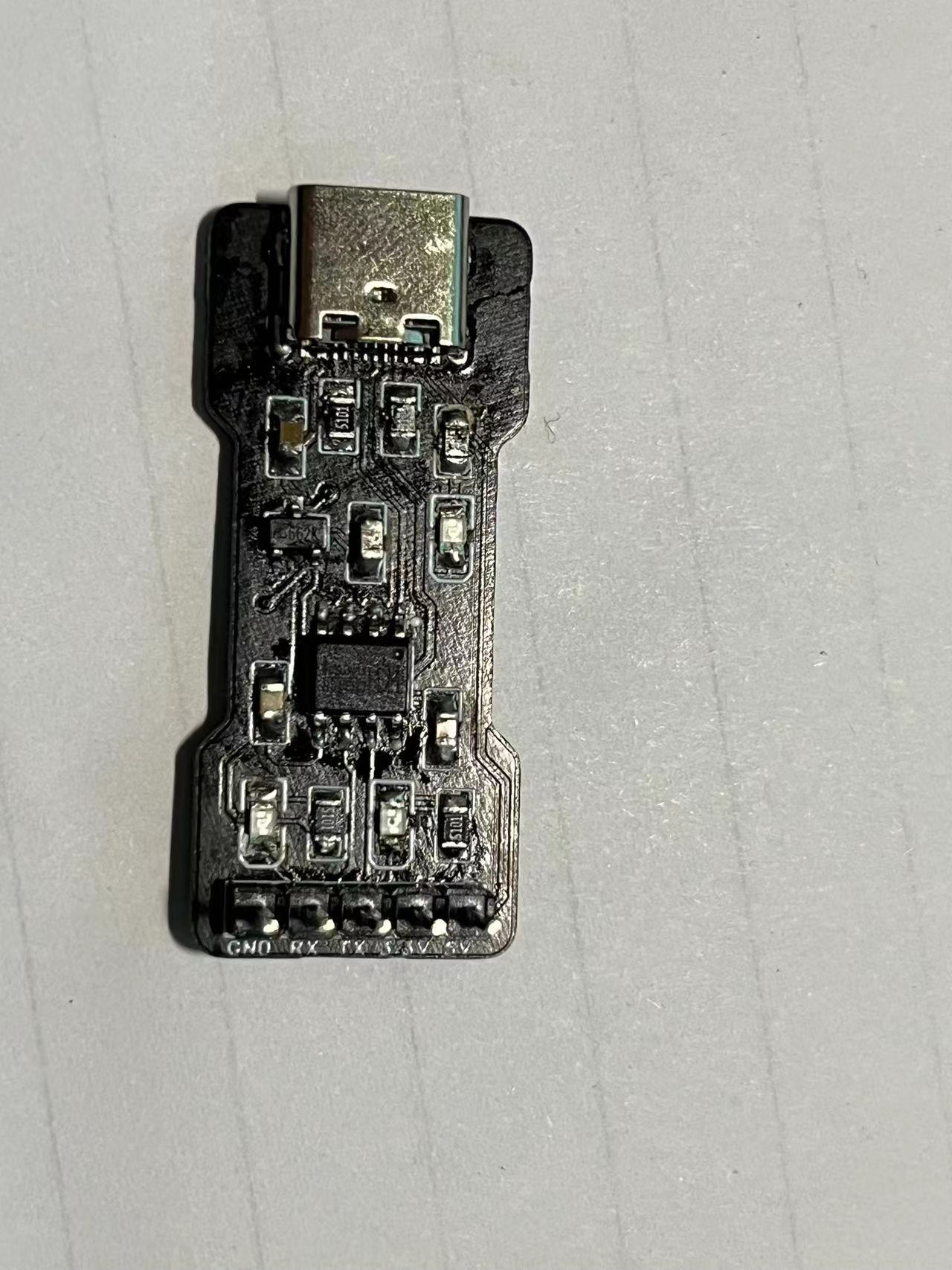
The RX pin of the CH340N connects to the TX pin of the microcontroller, and the TX pin of the module connects to the RX pin of the microcontroller. The silkscreen markings can be modified as needed.
PDF_CH340N Serial Port (Verified).zip
Altium_CH340N serial port (verified).zip
PADS_CH340N Serial Port (Verified).zip
BOM_CH340N Serial Port (Verified).xlsx
92589
TB6612 Four-channel Encoding Driver
TB6612 is a four-channel motor driver with 5V voltage regulation, a maximum current of 3A, and reverse connection and short circuit protection.
First version link:
https://oshwhub.com/fourteenzzh37/tb6612-four-way-coding-driver-bo

Project Introduction
Concept:
The TB6612FNG is a driver IC for DC motors, featuring a low on-resistance LD MOS structure output transistor. Through two input signals IN1 and IN2, one of four modes can be selected: clockwise (CW), counter-clockwise (CCW), short brake, and stop mode.
Characteristics
: Supply voltage: VM = 15V (maximum)
Output current: IOUT = 1.2A (average) / 3.2A (peak)
Low on-resistance output: 0.5Ω
Standby (power saving) System • Clockwise/Counter-clockwise/Short brake/Stop function modes
Built-in overheat shutdown circuit and low voltage detection circuit
Driver Circuit:
The TB6612 is a dual driver, capable of driving two motors; two onboard drivers allow for driving four motors, with additional power supply available. Truth table for
driving
PWM1A (connected to the microcontroller's PWM port)
:
AIN1 0 0 1
AIN2 0 1 0
Stop forward/reverse
A01
AO2 connects to two pins of motor 1. Truth table for
driving
PWM2B (connected to the microcontroller's PWM port)
:
BIN1 0 0 1
BIN2 0 1 0
Stop forward/reverse
B01
BO2 connects to two pins of motor 2.
The other two paths are similar.
The logic truth table
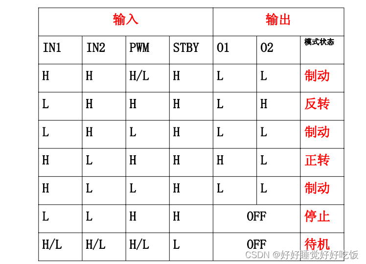
is as follows: When the STBY port is connected to the microcontroller's I/O port, clearing it stops all motors.
Project parameters and
usage functions: Timer output comparison, output PWM
. 1. Find the corresponding I/O pins according to the schematic diagram
. 2. Find the corresponding (timer and timer channel) in the chip datasheet (PWMA, B pins).
3. Enable the corresponding clock for the I/O port and the timer clock
. 4. Configure timer initialization: TIM_TimeBaseInit()
5. Configure the corresponding channel: TIM_OC3Init() / TIM_OC4Init()
6. Enable CRR preload channel register.
7. Enable ARR preload channel register.
8. Enable timer.
9. Set duty cycle (pass parameter value).
10. Control the motor according to the truth table.
11. Pass positive or negative parameters to control true reverse rotation of the motor.
First Edition.mp4
With short circuit protection and reverse connection protection.mp4
PDF_TB6612 Four-Channel Encoding Driver.zip
Altium_TB6612 Quad Encoding Driver.zip
PADS_TB6612 Four-channel Encoding Driver.zip
BOM_TB6612 Four-channel Encoding Driver.xlsx
92590
electronic


 京公网安备 11010802033920号

 HI3-0390-5


