5.1 Wireless Surround Soundbar for Karaoke (Strip Speaker)
1. Introduction:
Left + Center + Right + Rear surround sound + subwoofer, with wireless surround and subwoofer functions. Includes karaoke, vocal cancellation, and reverb functions.
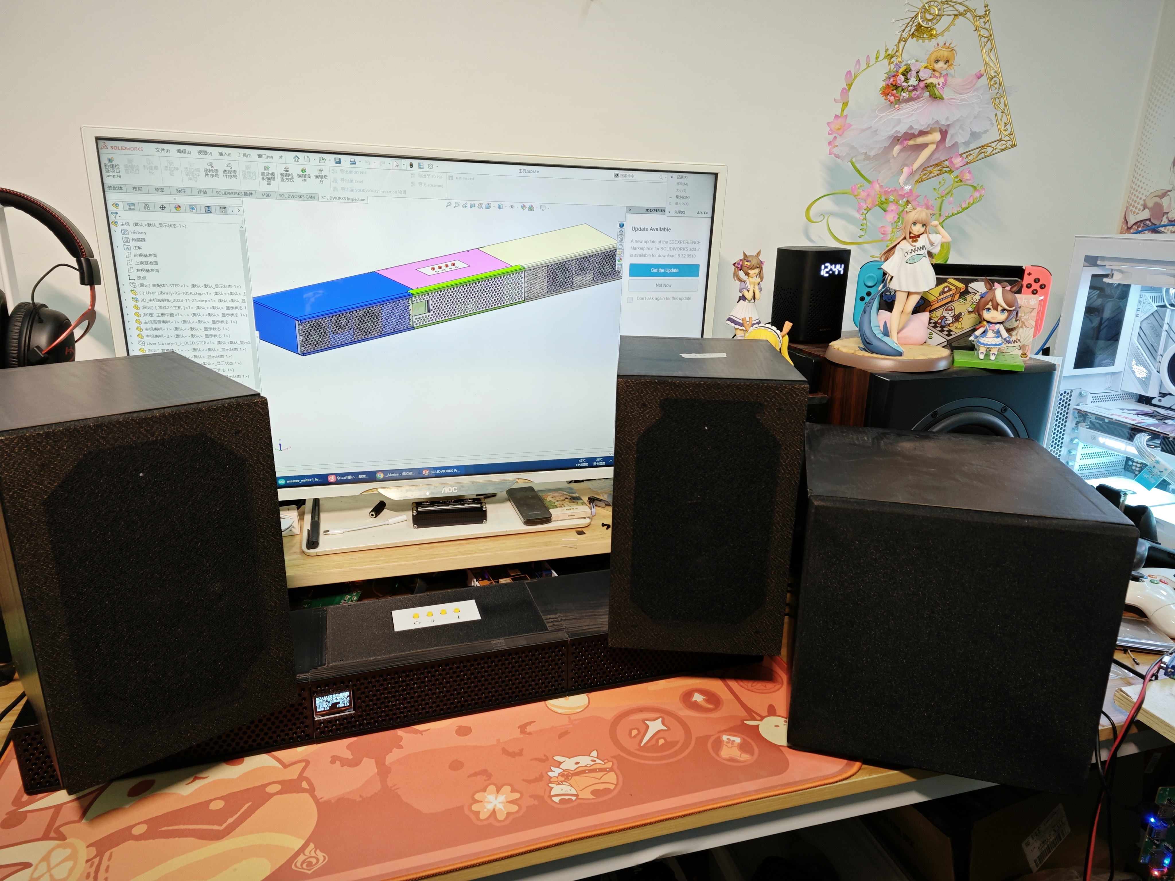
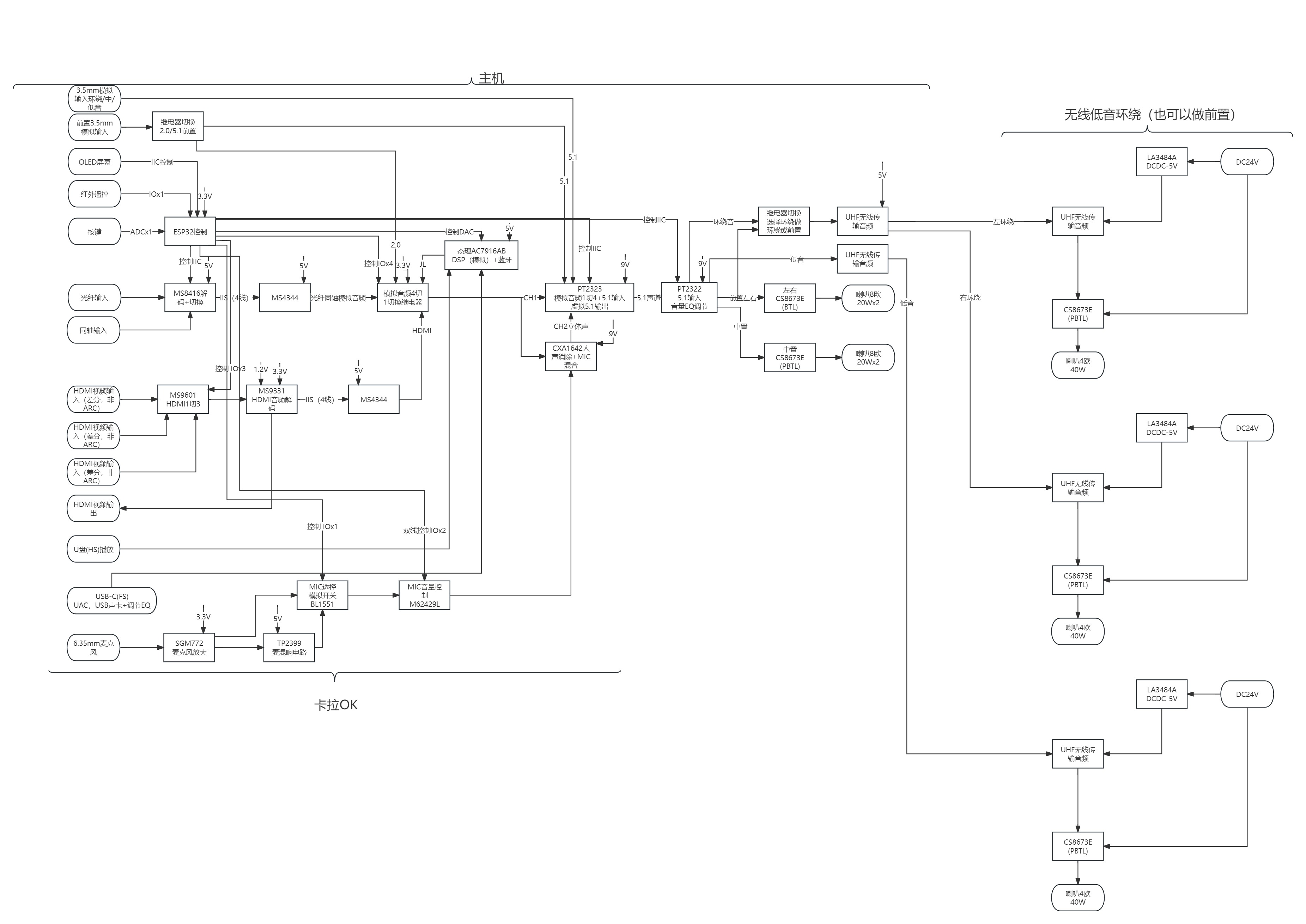
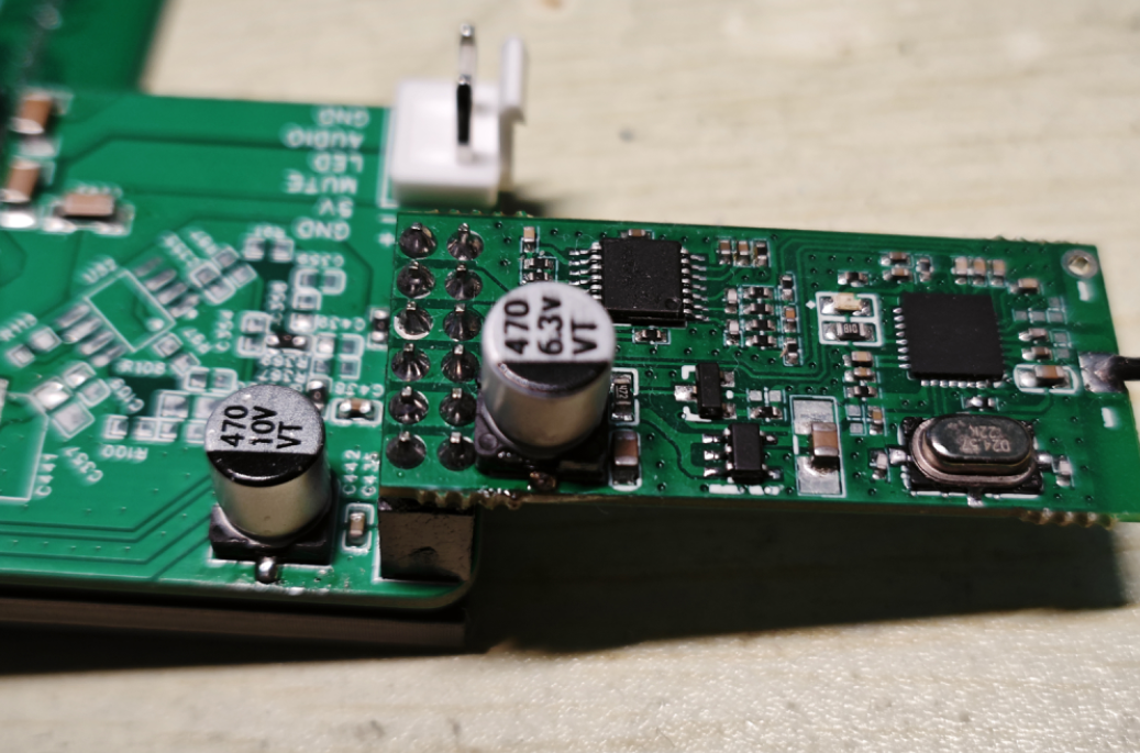
The system uses an 80W CS8673E amplifier, a PT2323 for virtual 5.1 audio mixing, a PT2322 for 5.1 channel volume control, a JL AC7916A for USB flash drive and Bluetooth decoding, DSP, DRC processing, an ESP32 for main control, a U-band wireless module for wireless transmission, an LMV358 for preamplifier, a PT2399 for reverb, a CXA1642P for vocal cancellation, an MS8416 for optical/coaxial decoding, and a CS4344 for IIS to analog audio conversion.
Special Features:
Directly mixes traditional 2.0 audio sources to 6-channel analog audio output;
wireless subwoofer and surround sound automatically pair upon power-on, allowing for flexible placement of
surround speakers; supports front
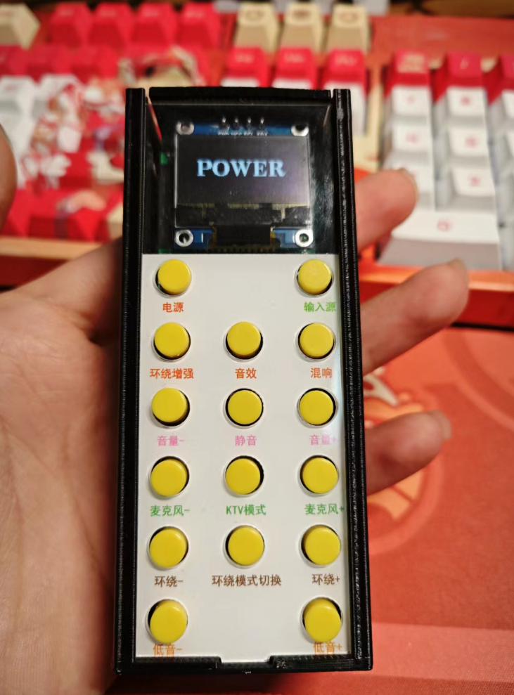
OLED screen; infrared remote control;
1.3-inch OLED screen;
peak power 80W*5=400W;
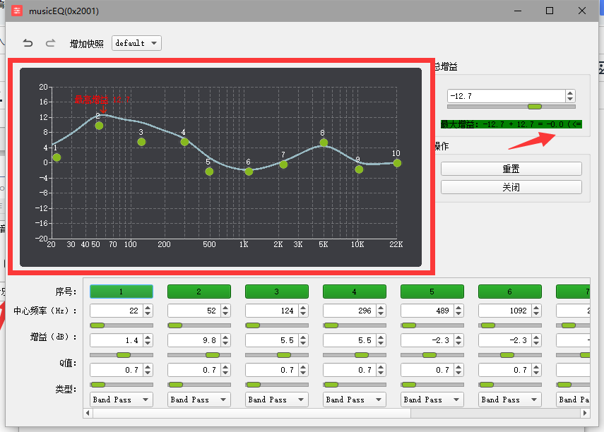
Jerry built-in DSP supports online EQ adjustment (10 bands)
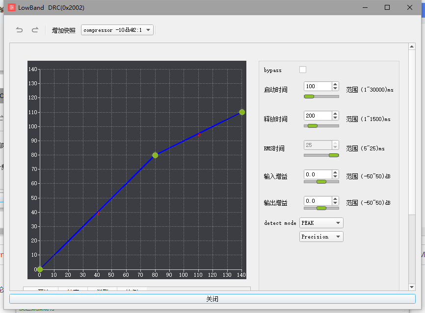
; Jerry built-in DSP supports DRC (LowBand DRC, HighBand DRC, full band DRC to be added later);
PT2322 supports EQ adjustment (3 bands)
; Karaoke Function:
Karaoke input music (except 5.1) supports vocal cancellation
; Karaoke supports vocal reverb or direct output;
Supported input sources:
Bluetooth (BLE V5.3 supports SBC)
, AUX (2 channels)
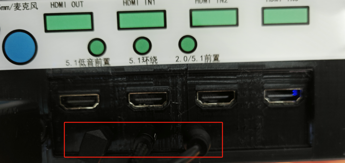
, 5.1 audio input (front left/right, surround left/right, center + subwoofer),
USB (supports AAC, ADPCM, AMR, APE, DTS, FLAC, M4A, MP1, MP2, MP3, OPUS, SPX, WAV, WMA, PCM audio decoding formats).
S/PDIF (supports sampling frequencies from 32kHz to 192kHz, 16-bit and 24-bit)
Coaxial (same specifications as S/PDIF)
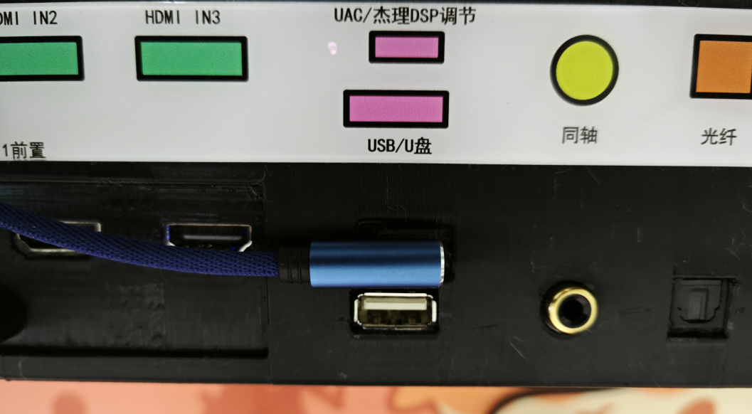
UAC (preemptive mode)
HDMI*3 (differential audio, non-ARC/eARC)
2. Before this... Dolby Atmos and DTS audio effects
have been implemented with 5.1 surround sound, why not add Dolby? Why not DTS?
Unfortunately, Dolby's R&D is not publicly available to individuals.
You can output virtual Dolby sound effects from software on your computer, many of which are free (such as Dolby on Bilibili, Dolby sound effects on Xiaomi phones, etc.).
For speakers to use Dolby sound effects, the hardware Dolby chip is indispensable
:
1. Patent issues are unavoidable; every Dolby hardware chip requires patent fees to be paid to Dolby.
2. Membership fees need to be paid to Dolby; companies need to pay annual membership fees to be eligible to develop and obtain Dolby-related materials and submit Dolby certifications.
3. Dolby chips available on Taobao are all salvaged, not brand new.
4. Strict confidentiality regarding chip data. Some chips are controlled via IIC or serial ports, but individuals cannot access register tables, command tables, timing tables, etc. Those who possess this data are bound by strict confidentiality agreements.
5. Dolby effectively controls these chips. Each company must report the quantity of Dolby chips delivered and their usage. The number delivered, the number actually used in machines and sold to users, the number damaged, the number lost, and the number used for research and development—all these details must be clearly stated and reported. Therefore, Taobao does not sell brand-new chips.
DTS maintains a similar level of strict confidentiality as Dolby.
3. Instructions for Use:
Wireless Surround/Wireless Subwoofer. Automatic pairing upon power-on, no other operation required
. Common input sources such as AUX, Bluetooth, optical, coaxial, USB, etc. No special functions are described here.
3.1 Standby/Power -On:
In standby mode, a dot is displayed in the upper left corner of the screen.
Power on using the remote control or buttons.
3.2 KTV/Reverb Function:
KTV is displayed on the OLED screen.
√ indicates KTV function is enabled ;

× indicates KTV function is disabled.

See the circuit section for the vocal cancellation principle.
In addition to microphones, a 6.35mm jack can also be used to connect electric guitars and other instruments, making it suitable as an instrument speaker.

See the KTV demonstration below for a KTV demo.
3.3 Sound Effects: Sound
effects include normal

bass

and subwoofer, with a heavier bass than the previous one for pop

and

jazz. The game features nine preset sound effects, including a blend of

2D

electronic

and

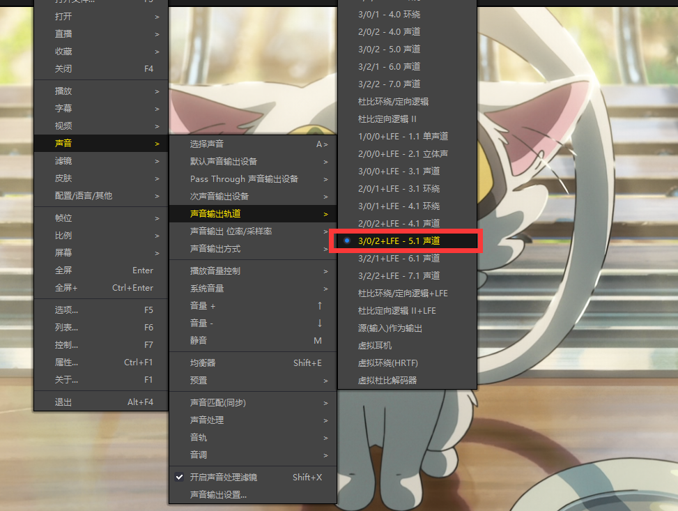
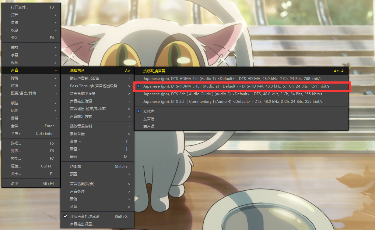
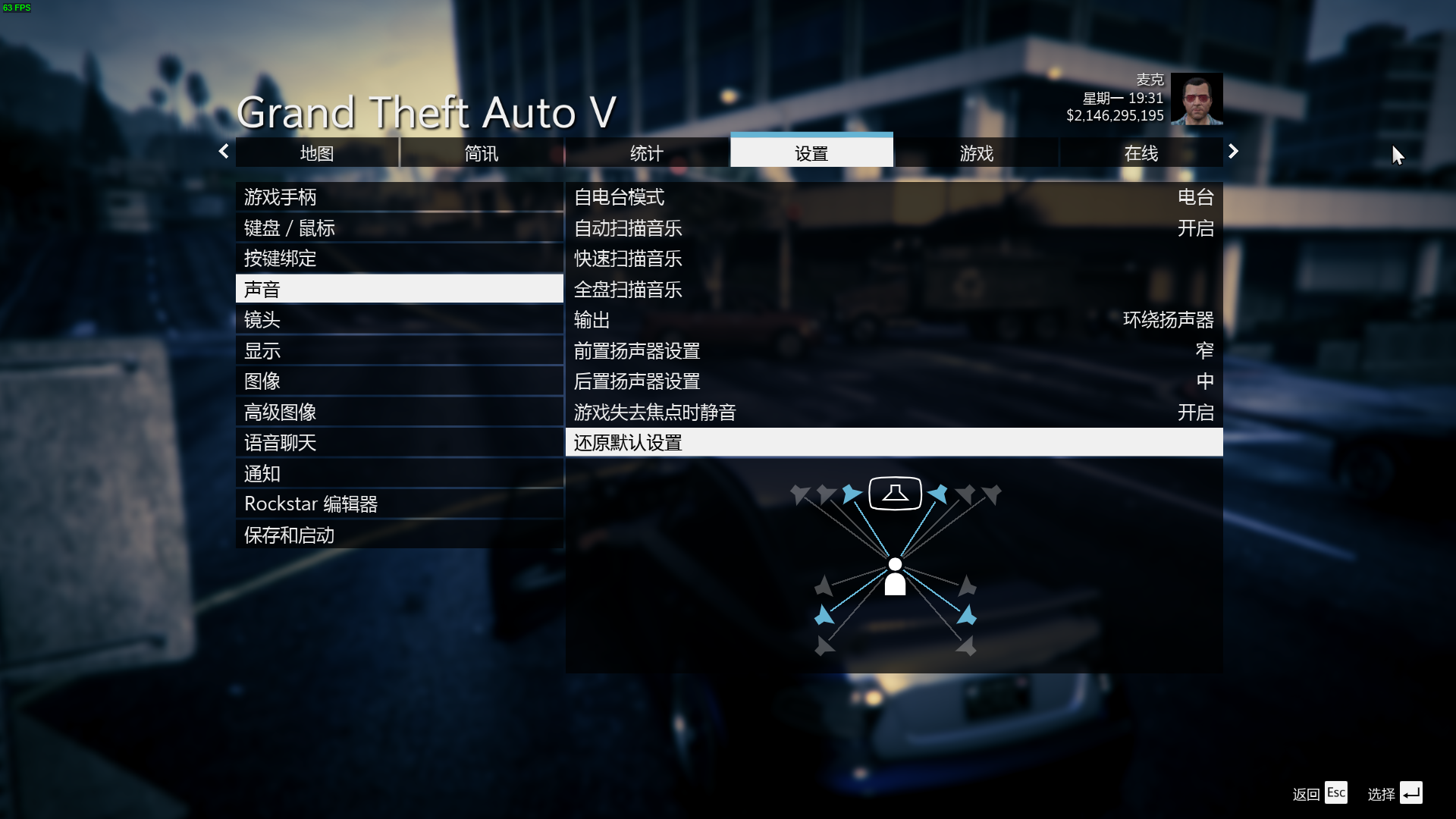
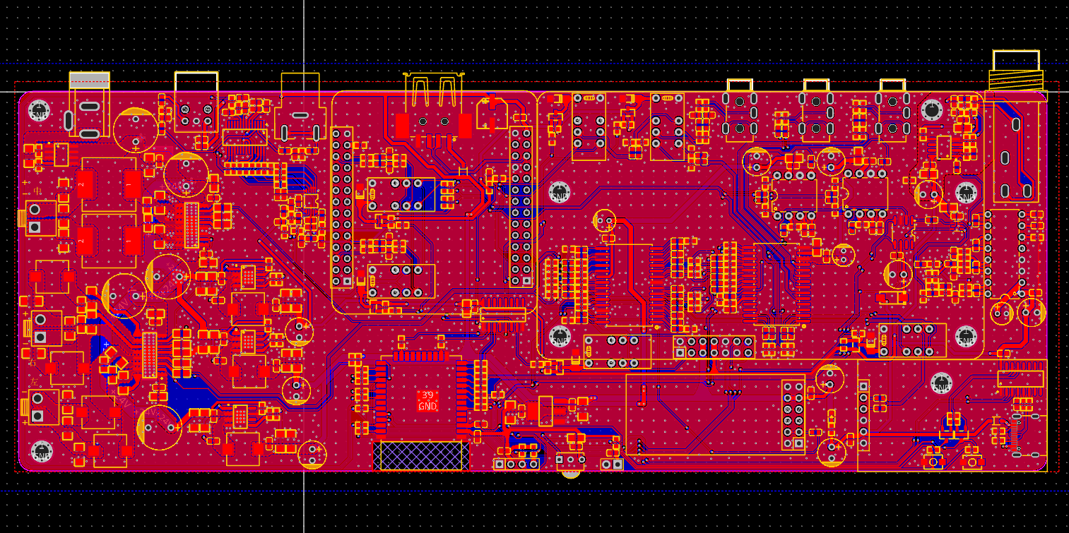
classic styles. Switching to the last preset, classic sound effect, and then back to normal will cycle through the various sound effects. Each effect has a different frequency response curve; choose one you like. See the demonstration video below for sound effects. 3.4 Volume Control System : The volume system is divided into four groups: Master Volume, Microphone Volume, Bass Volume, and Surround Volume. The microphone volume is independent of the other three groups and requires the 6.35mm device to be plugged in after turning on the KTV. The Bass and Surround Volumes are below the Master Volume. Controlling the Master Volume will also affect the Bass and Surround Volumes. Adjust the Bass and Surround Volumes according to your preference, the placement distance, and the angle of the surround speakers. The Master Volume ranges from 0 to 39 increments, the Bass and Surround Volumes from 0 to 15 increments, and the Microphone Volume from 0 to 32 increments. 3.5 Surround Effects There are two types of surround effects: Enhanced Surround Function (SUR) and 3D Effect Function (3D). Therefore, there are four combinations. Users can choose a combination that suits their speaker placement and desired effect. I personally recommend turning all of them on. 3.6 Surround Front Surround front means that the left and right surround speakers can be placed on either side of the main bar. The left surround becomes the left front speaker, and the right surround becomes the right front speaker, to enhance the front effect. Downward arrows indicate surround front; upward arrows indicate normal surround mode . 3.7 Input 5.1


This mode is a 5.1 mode with analog input. To create a true 5.1 system,

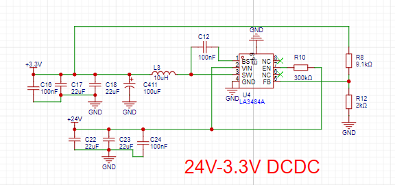
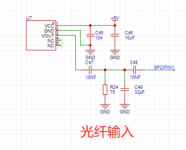
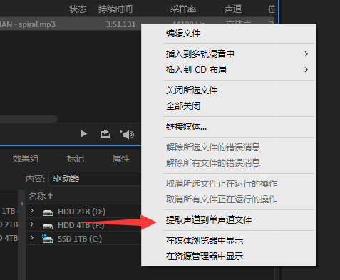
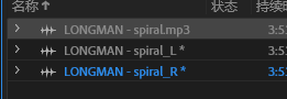
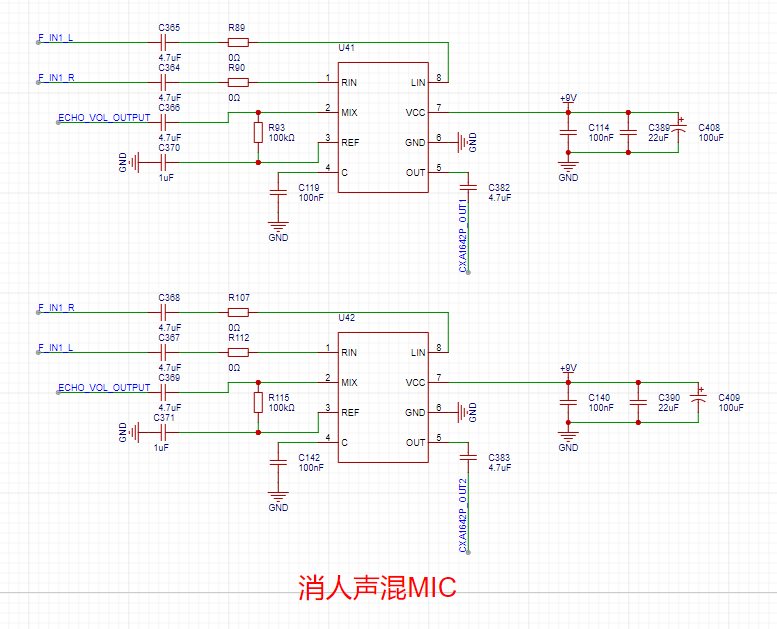
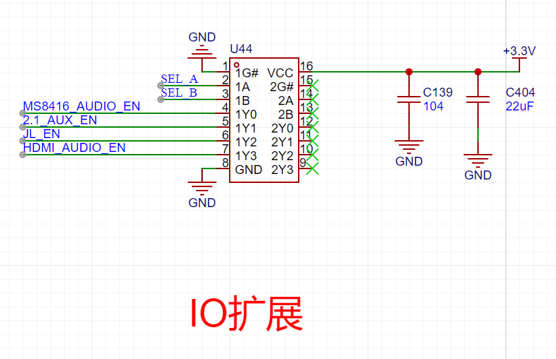
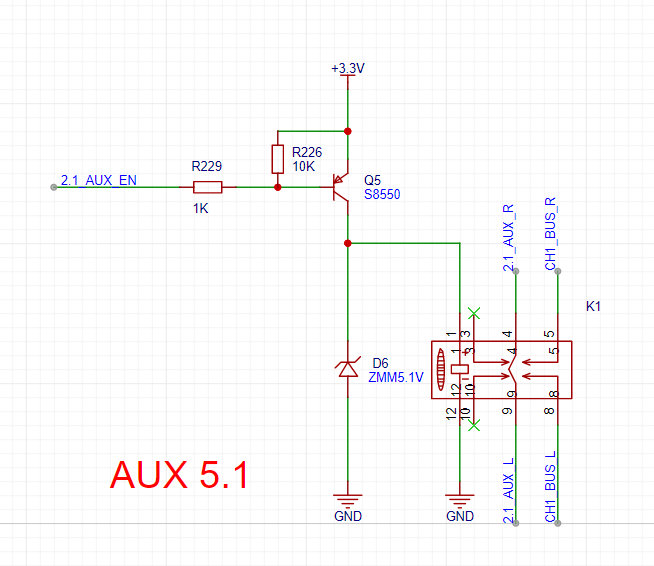
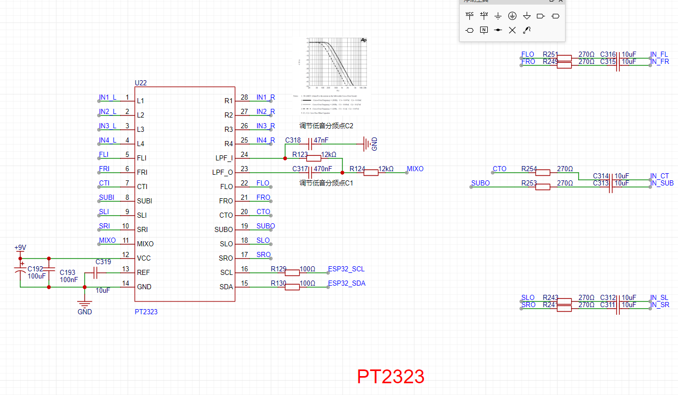
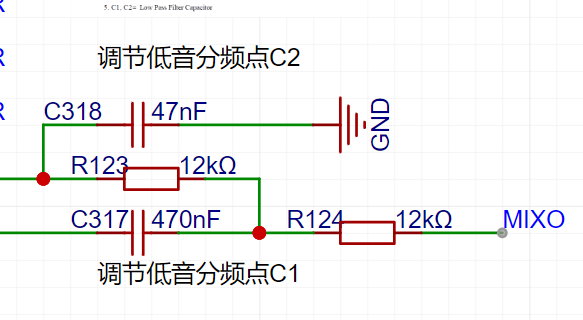
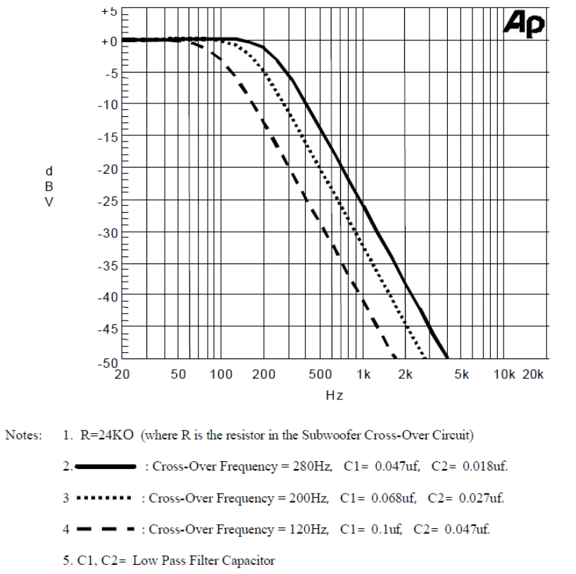
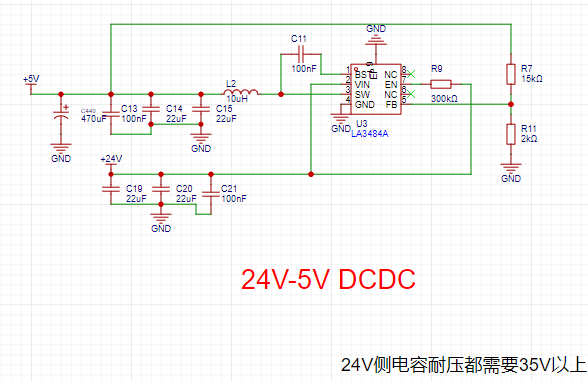
insert a 5.1 front subwoofer, a 5.1 surround sound, and another 5.1 front speaker. Other modes are virtual 5.1. The correct way to use this mode is to connect it to a computer motherboard with a 5.1 sound card and play source material with Dolby audio tracks. In the speaker configuration, select 5.1 surround sound and follow the steps. Taking PotPlayer as an example, you need to output 5.1 in the sound settings. The selected 5.1 is also virtual 5.1, simulated by the player (similar to virtual 5.1 on speakers). Then, select the 5.1 audio track in the sound selection. This is necessary to play the 5.1 audio track from a true 5.1 source. This mode requires a computer with a 5.1 audio output device. The computer can have an external sound card or use the motherboard's built-in sound card (most motherboards only have 2.0, so check if it supports it). The source material to be viewed needs to have a 5.1 audio track. Many games also feature 5.1 audio output; CS:GO used to have it, but CS2 doesn't. Of course, if you only have a 2.0 audio output device, using AUX mode to virtually create 5.1 can still provide a decent listening experience. This mode demonstrates a Dolby test demo and clips from the anime "Rin's Journey," the demo video is at the end. 3.8 HDMI Input : Select the HDMI input source. This HDMI audio is the audio transmitted within the HDMI port. When your computer or game console is connected to speaker input and output to a monitor or TV, switch to HDMI. For your computer, select the audio source as follows : Note! This HDMI is not HDMI ARC or eARC; it only decodes the audio 3.9 from the HDMI differential signal . For the USB sound card (USB AUDIO CLASS) , select the UAC input source . Connect the USB-C cable to the computer and plug it into the speaker's UAC input port. A USBAudio 1.0 device will appear on the computer, indicating the speaker's UAC input. This input can be used as the USB sound card's audio output. Note that this mode has higher priority than USB flash drives and Bluetooth. If the USB flash drive and Bluetooth are not playing, UAC will preempt the USB flash drive and Bluetooth 3.10. The remote control features an ultra-low power design. Pressing the button activates the OLED screen on the remote; releasing the button enters low power mode. One charge lasts for a year! Pressing the corresponding button will display the button on the screen and emit an infrared code value. 4. Design Block Diagram: The block diagram is quite complex ; click to enlarge. 5. Circuit/Principle : The system is quite complex; I will explain it in different parts. 5.1 Power Supply: The power supply uses LA3484, a domestically produced DC-DC converter. Adjusting the two resistors FB according to the datasheet will output the corresponding voltage. 5.2 Fiber Optic/Coaxial Decoding: Both fiber optic and coaxial inputs need to be connected to 75 ohms to ground for identification. S/PDIF decoding uses MS8416. The decoder uses a 3.3V input and I2C for control. In addition to I2C, an RST pin is also needed for reset. The MS8416 datasheet mentions that the reset pin needs to be fully pulled back after power-on. MS8416 outputs an IIS signal to CS4344 for IIS decoding, converting the IIS signal into a normal analog audio signal for the switching circuit, using a 3.3V power supply. 5.3 Microphone Amplification : An LMV358 low-dropout op-amp is used as the amplifier. 5.4 Microphone reverb uses a PT2399, with an input voltage of 9V. Adjusting the voltage division ratio of the two resistors here adjusts the internal clock frequency, thus adjusting the hysteresis time during reverb. 5.5 Microphone volume control and switching uses a BL1551 as a 2-to-1 switcher, allowing switching between the microphone input signal directly amplified by the op-amp and the reverb amplified signal. The user can select via remote control. The input uses a 3.3V power supply . Microphone volume control uses an M62429, a two-wire, 2-channel electronic volume controller with a 5V power input. 5.6 Vocal removal/accompaniment extraction principle. 5.6.1 Vocal removal methods : There are generally two methods for vocal removal: stereo removal and band-stop filter removal. Band-stop filter removal reduces the energy of a certain frequency range to zero using a band-stop filter, thus eliminating that frequency range of sound in the original signal. Stereo vocal removal is used here. 5.6.2 Basic Principle of Stereo Vocal Removal The basic principle of stereo vocal removal is that two signals with the same amplitude but opposite phase add up to zero. This is because the perception of stereo in music is due to differences in frequency, amplitude, and phase between the left and right channels of the accompaniment. Since vocals are always placed in the center during mixing, the amplitude and phase of the vocals in the left and right channels are essentially the same. Therefore, by inverting the phase of one channel and then superimposing the other channel, the vocals can be canceled out, leaving only the accompaniment. Disadvantages : 1. This method will remove elements with similar properties to vocals, such as drums and bass in the accompaniment. 2. The input music must be stereo; single-channel music cannot remove vocals. 3. The resulting sound is a single-channel mixed music. 5.6.3 Theory and Practice If you don't have a PCB but can use AU for theory, it's simple. First, import an audio file, then separate its left and right channels into L/R. Then, open one of the channels and use the phase inversion effect (note: not reverse the direction, but the direction of the L channel). Then, create a new multitrack and mix the inverted L channel with the separated R channel . The result will be a sound without vocals, only the accompaniment and harmonies. 5.6.4 Vocal Removal Circuit Principle The CXA1642P is a karaoke vocal removal IC manufactured by Sony, used in audio equipment, CDs, etc. This chip is now discontinued; those purchased on Taobao are either used or leftover stock. As mentioned in the previous sound removal method, this method removes elements with similar properties to vocals, such as drums and bass in the accompaniment, which are low-frequency instruments. Therefore, we only need to create a low-pass filter on one channel of the original music to obtain the bass, and then mix the music with the bass (after removing vocals) to better preserve the low-frequency components. The CXA1642P has already integrated this function internally. A drawback mentioned is that the output is a single-channel mixed music.


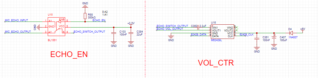


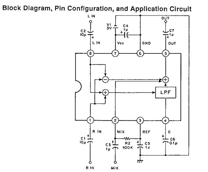
The left channel's phase inversion mixes with the right channel to produce the right channel's accompaniment. Therefore, by adding another channel to invert the right channel and mix it with the left channel, a stereo accompaniment can be produced. Two CXA1642P amplifiers are sufficient. However
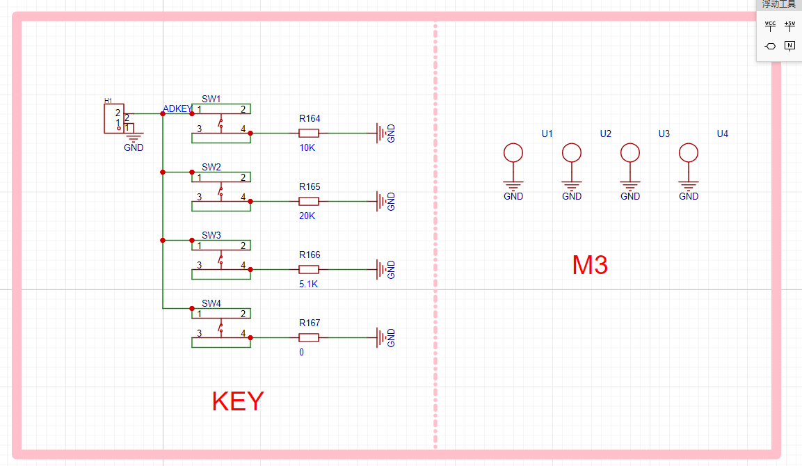
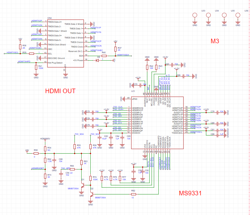
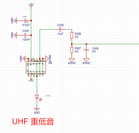
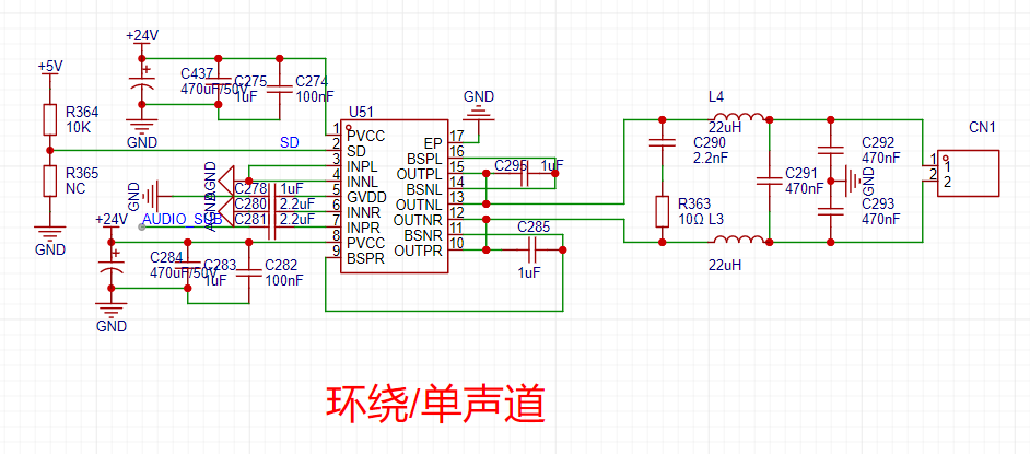
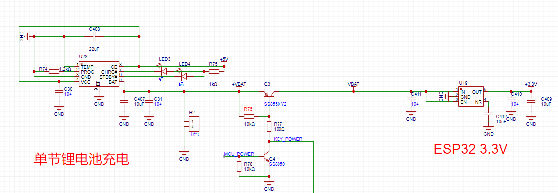
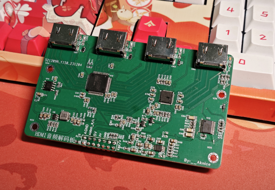
, since it's a stereo effect created by mixing two mono channels, the stereo effect is weak or almost nonexistent. The microphone signal is input to the CXA1642P via the volume controller. The 5.7 amplifier uses two CS8673E Class D amplifiers with a 24V input, capable of 80W at 10%. One amplifier performs BTL (Block Streaming Transmission), approximately 40W x 2; the other performs PBTL (Plain Streaming Transmission Transmission), 80W x 1 for the center channel. PBTL requires a high-current CDRH12 x 12 inductor, while BTL only requires a CDRH7 x 7 inductor. Note the voltage rating of 5.8. The switching uses relays to switch input sources . Due to insufficient I/O, a logic switcher is used for 4-channel switching. The logic controller uses 3.3V for switching, and the relays also need 3.3V to switch each source onto the analog audio bus . The cable enters CH1 of the PT2323, while the cable that has passed through the CXA1642P vocal cancellation circuit enters CH2. Therefore, the cable on CH1 is switched using a relay before entering the PT2323. The PT2323 uses I2C control here to adjust the bass crossover point. Since the 5.1 preamp and AUX input use the same AUX port, but the actual input to the PT2323 is separate, an additional relay is added here for switching between stereo and 5.1 input. 5.9 Volume Control: The PT2322 is used for 5.1 volume control, with a 9V power input and I2C control. 5.10 MCU: The MCU uses an ESP32 with an independent 5V to 3.3V LDO power supply. All I/O pins are used here; other I/O pins either have special power-on requirements or cannot be upgraded after connecting other components. The buttons are connected to the ESP32 using an ADKEY. The OLED screen is connected to the I2C bus, and the remote control head is directly powered, outputting the remote control signal. 5.11 Jerry Control: Jerry handles Bluetooth, USB decoding, and UAC using a female connector connected to the Jerry core board above. The USB signal is given to the USB connector . The core board uses ADKEY control, so the ESP32 uses a DAC to control Jerry's functions. 5.12 Wireless Transmission: Wireless transmission uses an external module. We only need to give the audio signal from the PT2322 to the wireless module. For the surround module, add a relay to switch the surround speakers as front or rear. The wireless module has high power requirements, so add more filter capacitors. 5.13 Button Board : The button board connects to different value resistors from the ADKEY. It is recommended to use precision resistors. The values are already marked; do not place them incorrectly, otherwise they will not be recognized. Reserved screw holes. 5.14 HDMI Decoding: HDMI has a separate motherboard, a four-layer board within a 10x10 area. It can receive 5V and 3.3V power inputs, and has an internal 3.3V to 1.2V DC-DC converter. The HDMI 1-to-3 switch uses the MS9601A. Three sets of HDMI signals are input, and the HDMI signal output from the MS9601 is then input to the MS9331. The MS9331 outputs HDMI signals and simultaneously decodes the IIS signal. The CS4344 performs IIS decoding, extracting the analog audio signal, which is then fed into the motherboard's switching relay onto the bus. 5.15 The JL core board is basically copied from the previous JL development board: https://oshwhub.com/aknice/jie-li-ac7916a-he-xin-ban 5.16 The wireless subwoofer/surround sound uses the same schematic and PCB. The main function is to receive wireless signals and then input them to the amplifier. The amplifier is still the CS8673E, PBTL, 80W, 24V input. The DC-DC converter is also the same LA3484, except that only 5V is needed here. 5.17 Remote Control The remote control section is primarily designed for power saving. Q3 only conducts when KEY_POWER is grounded. Please note that the values of resistors R76, R77, and R78 should not be changed, otherwise the transistors will burn out. Therefore, in addition to one pin connecting to the MCU, the button also needs another pin connected to KEY_POWER. Q4 is connected to MCU_POWER. When a button is pressed, the MCU will immediately pull MCU_POWER to prevent power loss until it automatically shuts off after a period of inactivity. IO4 is connected to the infrared transmitter. If the transmission power or distance is insufficient, R99 can be reduced. The rest are standard circuits and will not be detailed. 6. LAYOUT 6.1 Subwoofer Surround Board Both surround and subwoofer circuits use this board. This board is relatively simple; no amplifier circuit is used. 6.2 The button board is relatively simple, nothing much to say. 6.3 For the mainboard , pay attention to the analog audio traces. Avoid routing them under power components and inductors, as this will cause interference. The entire board doesn't have separate GND and AGND, but noise suppression is good thanks to the optimized analog traces. The board is quite large, so JLC cannot be used for free. The board customization cost is approximately 60. 6.4 The HDMI board carries high-speed HDMI signals. The trace differential is controlled within 5mil. Since it's smaller than 10x10, a four-layer PCB is used. It can be used for free! 6.4 Remote Control Board: The remote control board is small in size, so accommodating so many components is difficult. The wiring is straightforward; there are no special signal routing issues. 7. Impedance Matching: HDMI requires 100 ohms impedance on a small HDMI board, a 4-layer board with a thickness of 1.6mm. 8. JL AC7916 Chip Code: For programming instructions, please refer to my previous project: https://oshwhub.com/aknice/jie-li-ac7916a-he-xin-ban. Simply put, press the flash button, power on, compile with Code::Blocks, and then program the chip. I won't go into detail here; the code is in the JL host file in the code.7z attachment. You can use the Wi-Fi story machine code from the official SDK. Currently, much of the code is unnecessary, as we only need Bluetooth and USB playback.


However, the logic and kernel within the Jerry code are very complex. I strongly advise against deleting useless code such as network playback functionality.
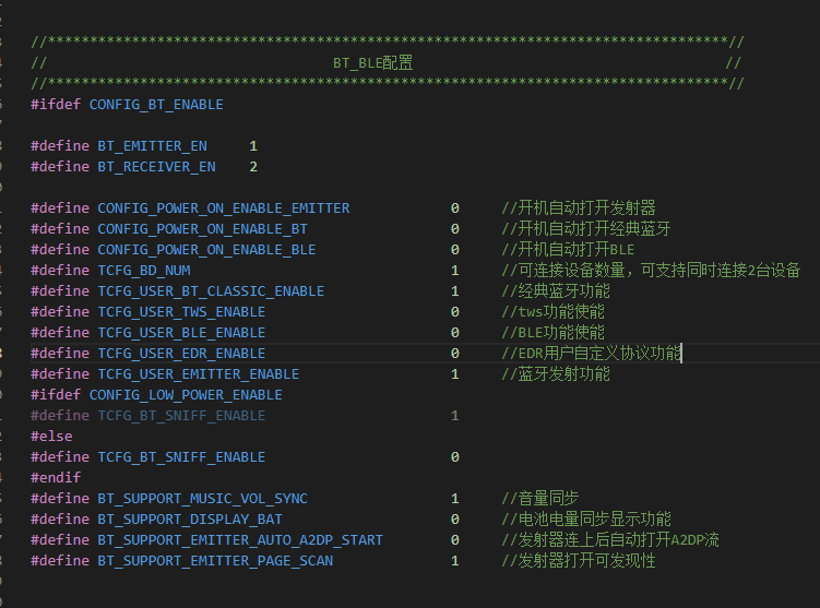
In app_config.h, you can enable the TWS switch and Bluetooth switch; the settings are as follows.
Before using EQ, you need to configure the EQ switch. The USB online EQ switch and

LINEIN gain sampling adjustment settings are as follows.

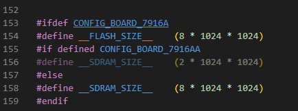
To disable network configuration, the board-level configuration
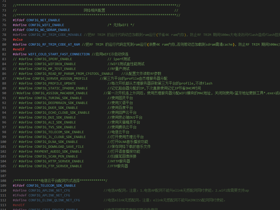
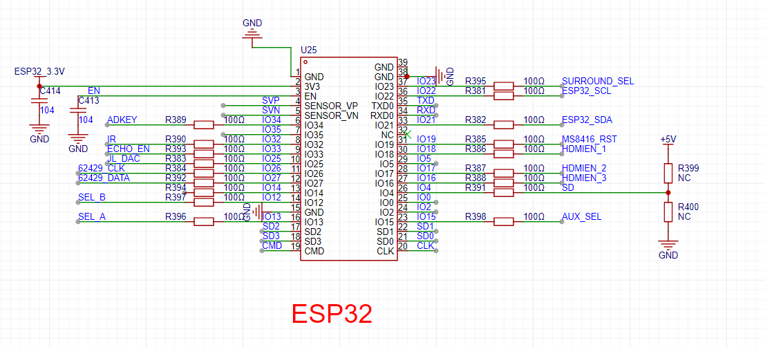
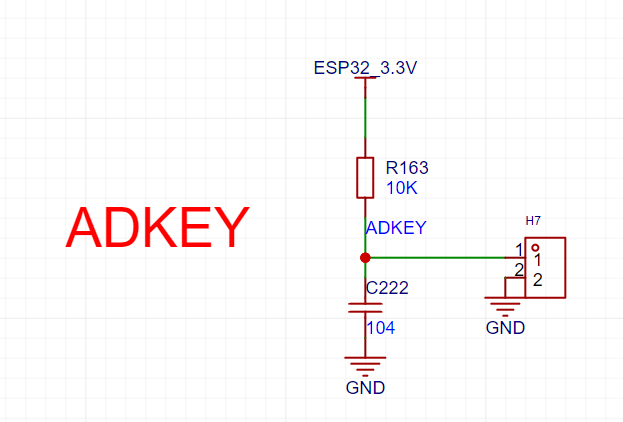
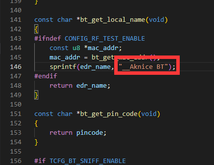
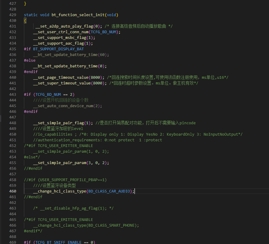
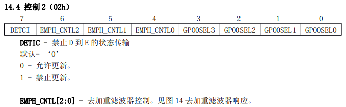
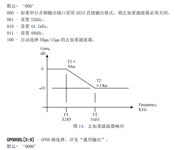
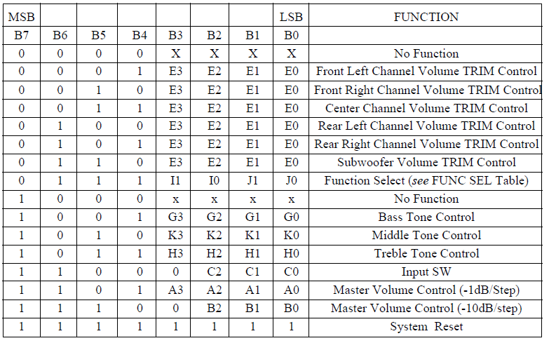
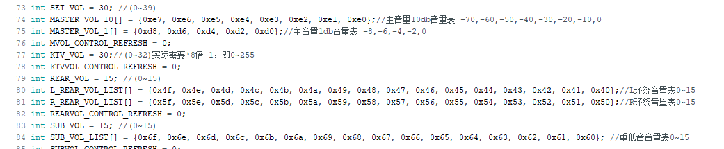
in board_config.h is as follows, and the FLASH configuration is as follows. In app_music.c , the LINEIN mode requires adding the EQ configuration code before the decoder to take effect. In user_cfg.c (fw-AC79_AIoT_SDK-release-AC79NN_SDK_V1.1.0appscommonconfig), you can modify the Bluetooth name. In bt_music.c , disable the pairing input PIN code and set the Bluetooth type as follows. In app_music.c, you can set the button response and corresponding button operations. In app_music.c, you can set the maximum and minimum volume, initial volume, and volume step size. After setting the volume, powering off will save the current volume, and powering back on will restore the previous volume level. For USB flash drive decoding, the following codec needs to be opened to decode various USB flash drive file formats: 9. ESP32 Code. This part of the code is extensive, divided into two parts: remote control (remote transmitter) code and host code. A few key points will be discussed. The platform uses an Arduino platform and requires the IRremoteESP8266, u8g2, and M62429 libraries. The host code is burned via internal TYPE-C; the code must be burned before assembly. 9.1 MS8416 Optical/Coaxial Decoding Section . The MS8416 is a circuit that receives and decodes digital audio data. It supports IEC60958, S/PDIF, EIAJ CP1201, and AES3 interface standards. The MS8416 has both software and hardware modes, selectable according to different needs. Channel status data is stored in registers for easier reading. GPIO pins offer high flexibility, allowing selection of different signal outputs. After the S/PDIF signal enters the MS8416, it outputs S/PDIF and I2S signals. The I2S signal is decoded using the MS4344 to produce analog audio . In hardware mode, this project connects to an ESP32 IIC and does not use hardware mode. For details on using hardware mode, please refer to my other project: https://oshwhub.com/aknice/ms8416-demo . Software mode offers two options: SPI and I2C. If the RST pin is set high and there is a high-to-low transition on the AD0/CS pins, SPI mode is selected. Connecting a resistor from the AD0/CS pin to VL or DGND selects I2C mode. Therefore, the desired AD0 address state is fixed. The default software mode uses I2C. The I2C address is 0 0 1 0 AD2 AD1 AD0 0. The software pins are as follows: Software register operations: MS8416 mainly operates on registers 0x00~0x09. 0x00 is generally 0x80, which is sufficient for using a high update rate phase detector. The others are default . 0x01 is generally set to restore the master clock frequency. 0x02 = RMCK, the output frequency is 128*Fs. The others are default. Setting 0x00 to 256*Fs can be used. There is noise in the decoded input device. The HOLD bit needs to be set. When a reception error occurs, the received audio sample is processed as follows: 01 - replace the current audio sample with 0 (mute). That is, when there is no input or an incorrect input S/PDIF signal, if the HOLD bit is not set to mute, there will be a lot of noise. Finally, it is recommended to set the 0x01 bit to: 0x05 0x02. Because we set the S/PDIF output pin to the GPO0 pin in the schematic, set GPO0 to 04. Select the S/PDIF output from the RX register. If the TX pin is selected, the register is set to 0x0B, meaning GPO0SEL3, 1, and 0 are 1, and GPO0SEL2 is 0. The corresponding code is as follows: GP0 is used as TX. TX can be selected in register 0x04. 0x03 remains the default and is not set. 0x04 7 bits are the working bits for the 8416, controlling whether the 8416 is in sleep or normal operation mode, with a default setting of 1. Bit 543 is the RX selection bit, used to select the input for output to IIS. Bit 210 is the TX selection bit. If GP0 is configured to output TX in 0x02, then the TX bit is selected here. 0x05 This register mainly configures IIS . Configuring 0x85 sets IIS to master mode. Bit 3 sets IIS left and right alignment; changing this bit can reverse the left and right channels of IIS 4344 decoding. 0x06 Error bit masking, set to 0x17. 9.2 SOURCE Switching Section The source section defines an enumeration, listing all sources. Since there are two places where the source will be switched: remote control and machine buttons, taking a button as an example, after the ADC is detected, dosourceswitch() will be executed. The `dosourceswitch()` function enumerates the source codes to the next source code, then sets a flag of the next source code to 1. The main program continuously monitors the source status. The `sourceswitchstate()` function loops continuously. Some sources have flags indicating that switching to this source only performs certain operations once, and then stops. For example, switching a relay or setting the PT2322 switch. This switches to the corresponding source code and completes the necessary tasks. 9.3 Volume Control Section: The master volume and surround bass volume controls are both done in the PT2322. The corresponding registers in the PT2322 are as follows: The master volume control bits range from 0 to -79dB. The corresponding volume controls are displayed as a volume table in the program. The surround and bass volumes range from 0 to 15dB. The master volume is divided into 10 levels and 1 level.


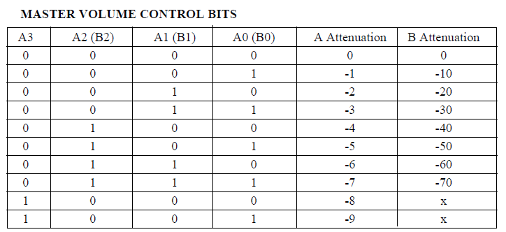
The MVOL_CONTROL() function establishes a correspondence between the master volume range of 0-39 and the actual control range of 0-79.
The algorithm is as follows:
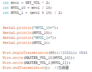
The main program detects
volume changes via remote control and buttons.
Taking buttons as an example

, it controls the volume from 0-39. Pressing a button increases or decreases the volume by setting the SET_VOL value,
then updating the volume flag MVOL_CONTROL_REFRESH, and
finally executing the operations within MVOL_CONTROL().
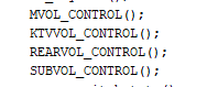
The surround sound, bass, and microphone volume control logic is similar.
The microphone setting for the M62429 chip ranges from 0-255; for simplification, only levels 0-32 are set, each corresponding to an 8dB volume of the M62429
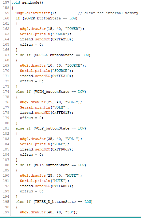
. In the sound effect control section,
we first set the various sound effects in the enumeration. These
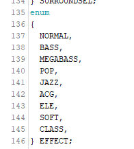
sound effects only change on the remote control. Looking at the remote control section,
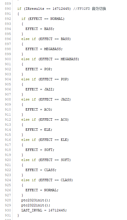
we see that the switching is very abrupt:
if a sound effect button is detected being pressed under the current sound effect, it directly switches to the next sound effect state. This simply changes the state and then reinitializes the 2323 and 2322 chips.
The changes are in the code of the 2323 and 2322.
Continuing with
the 2322 code, we see different curves for sound effect control. Setting

three frequency points allows for different sound effects.
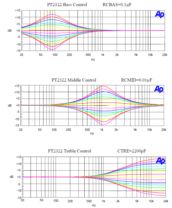
For example, for bass, the bass curve is raised; for mid-range and treble, it's lowered ;
for pop music, the mid-range is raised; for soft music, the treble is lowered
; and so on.
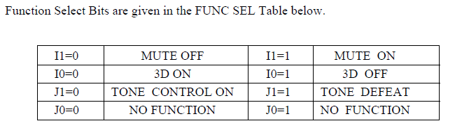
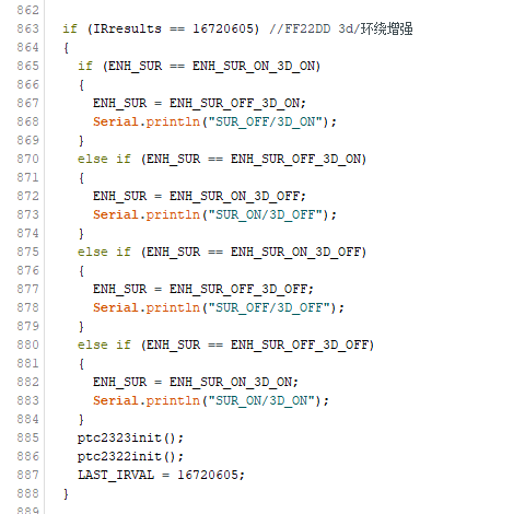
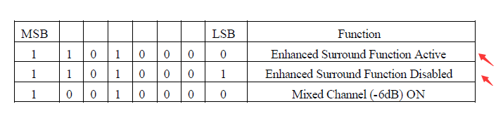
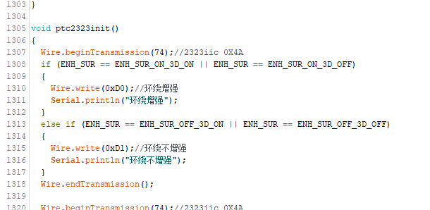
Other examples are omitted; you can check the code. Additionally, the sound effect function requires enabling the 3D sound effect in
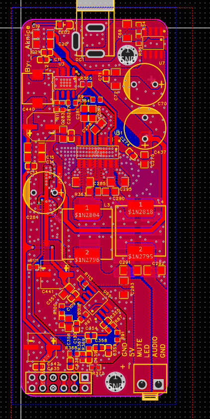
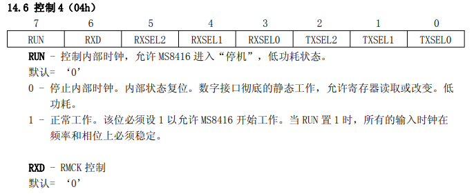
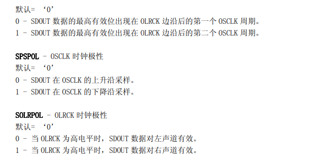
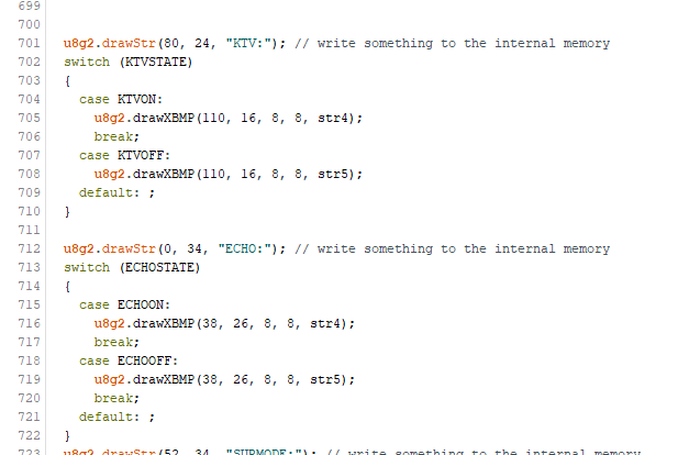
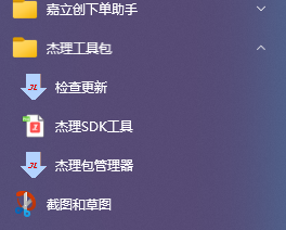
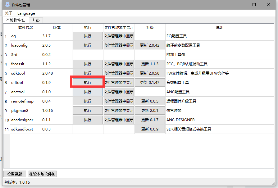
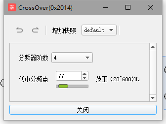
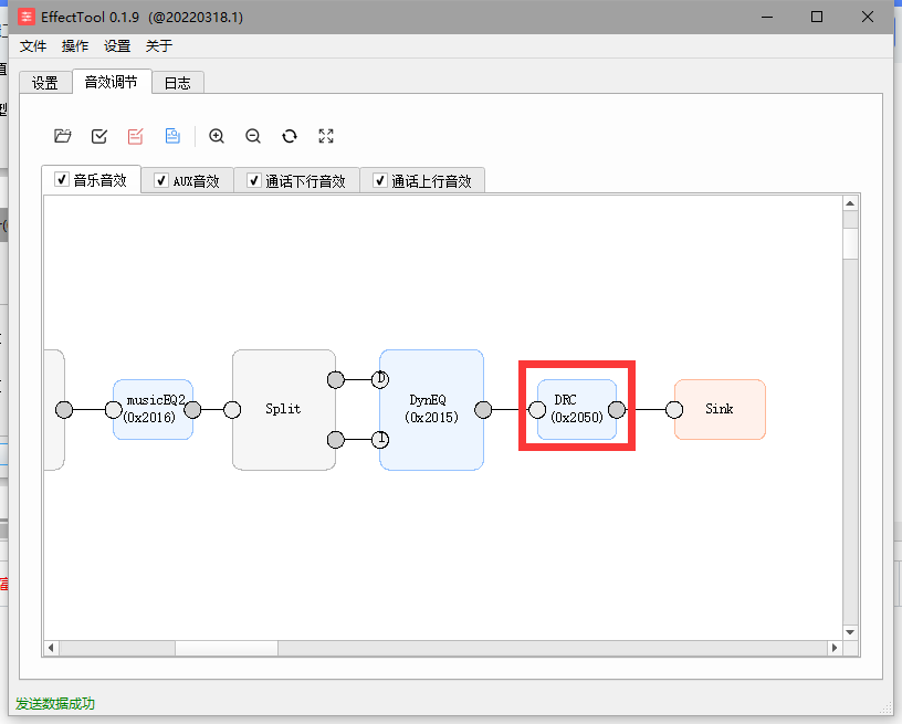
bit 0111 (J1 bit). This function is also located in this bit . This function only works on the remote control. Again, the remote control simply switches to the next state and then reinitializes the 2323 and 2322. 2322 simply controls bit I0 of bits 0111, while 2323 controls bits 1101 (0 and 1). Therefore, writing D0 or D1 is sufficient, resulting in four combinations . 9.5 Remote Control Receiver (Host) Section : We've already discussed the remote control. It's constantly being detected in a loop. When a value is detected, it's sent to IRresults . We then determine which value this IRresults equals, and that value corresponds to the function. For example, the KTV button value is FF9867, which is 16750695 in decimal, so it executes the KTV on/off action. However, there's another situation where the button is continuously pressed, such as volume up or down. If we keep pressing, we want to continuously increase or decrease the volume. But the above only applies to a single press. Therefore, we need to introduce a LAST_IRVAL to store the previously pressed remote control value. When the remote control is pressed, the corresponding button code value is sent, for example, volume + is 0xFF906F. That is, 16748655. After a long press, it won't continue sending 0xFF906F, but instead sends 0xFFFFFF. Because we are using NEC's code value encoding method, our machine detects 0xFFFFFF and considers it a long press on the remote control. However, at this time, the value of IRresults has been overwritten by 0xFFFFFF. Therefore, a LAST_IRVAL is needed to store the previous value to determine which button was long-pressed. See the code below: 0xFF906F is pressed once, which is volume +. Then LAST_IRVAL is assigned the value 16748655. When LAST_IRVAL is 16748655 and the current IRresults is 0xFFFFFF, which is 16777215, it is determined that volume + was long-pressed. The operation is actually the same as the normal volume +, but with a delay, so that the volume cannot be increased too much at once. 9.6 The remote control transmitter (remote control) section is designed for low power consumption. Therefore, upon power-up, we first pull the MCU_POWER high for self-locking before other operations can be performed. First, we detect which button is pressed and set the pressed and released states before sending the corresponding code value. As mentioned earlier, when the button is pressed for a long time, the remote control sends a value of 0xFFFFFF. Therefore, when the button is not released, it will continuously send 0xFFFFFF until the button is released. After the button is released, a timer will start to accumulate the offset value. When the button is pressed, the offset value is reset to 0 and re-accumulated. When a certain value is reached (set to 40, i.e., 8 seconds), the power will automatically turn off and enter low power mode. 9.7 The OLED part of the host is relatively simple. It is just to display the corresponding value by enumerating. For example, source is displayed as KTV through source enumeration , and echo is displayed through echo state enumeration. 10. JL EQ and DRC adjustment Note: Currently, this JL EQ is only for Bluetooth mode. You can connect the LINE IN to the AUX bus and modify the code so that the analog audio source can be adjusted through the Jerry DRC and DSP. Before adjusting the EQ and DRC, according to the environment configured when debugging and burning the Jerry chip, the "Jerry Package Manager" application will appear in your computer's Windows menu. Before using the package manager, it is recommended to check for updates to the latest version and then debug. Select efftool and select ATK, do not select EQ. Plug in the USB, and the serial port device will be recognized. Click to open. In this tab, you can set EQ, crossover point, and DRC. Other tabs are not effective. The EQ setting curve is shown on the left. It is not recommended to set the maximum gain to 0dB. You can reduce the total gain to reduce the maximum gain. Crossover point settings are low and high. DRC settings can be enabled in the code. 11. Electroacoustic performance test According to the datasheet, it can reach 80W under a 24V 4Ω load. THD+N=10% The actual test results are as follows: Under a 1KHz signal with a 1V input, the output power reaches 80W. The THD+N=15% is slightly different from the specification, possibly due to insufficient adapter power causing voltage drop and increased distortion. The actual result is basically consistent, with peak power reaching 80W*5=400W.


Recommended power adapters:
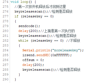
Main unit: 24V 5A;
Subwoofer: 24V 4A
; Surround: 24V 3A.
Purchase link:
https://detail.tmall.com/item.htm?id=678841720927&spm=a1z09.2.0.0.42d72e8dSWwgbp&_u=mqavhl82f20
12. Modeling/3D Printing the Shell
A soundbar is essentially a long, bar-shaped speaker, significantly longer than a regular speaker. This length necessitates different manufacturing processes compared to traditional wooden speaker
enclosures. Currently, there are two main approaches to soundbar shell production. While we wouldn't make them ourselves, I'm simply introducing the industry.
One approach is pure mold making, where a single piece of plastic shell is created. This method offers good integrity and is inexpensive; a 1-meter-long plastic shell costs less than 10 RMB. However! The cost of mold making starts at 50,000 RMB – expensive!
One method involves using long PVC pipes with speaker holes and PCB holes cut in the middle. This type of casing requires additional small shells for edging the front and back of the pipe. These pipes can be made very long and are quite sturdy. The mold cost is only 2,000-3,000 yuan, but the pipes themselves are expensive, costing 40-50 yuan per meter.
While wooden crates can also be used to make long strips to form a soundbar, wooden crates are more expensive, as are the labor costs. Therefore, soundbars rarely use wooden crates, although it's not unheard of.
12.1 Modeling
: The main bar, remote control, and surround/subwoofer rear panel
were modeled using SolidWorks. Printing materials used were Tianrui's PETG materials: https://item.taobao.com/item.htm?spm=a1z09.2.0.0.67002e8dwEhS93&id=679771198504&_u=mqavhl85bce.
The printer used was a Tuozhu P1P, with Tianrui's default settings. For Tuozhu configuration
, consult the Tianrui seller. The modeling files are attached; they are in multi-part compressed format, please download and extract all parts.
(By the way, open-source platforms only allow attachments up to 50MB.
) 12.2 The main bar
is modeled as follows:
The main bar is approximately 720mm long, divided into 3 sections for easy printing by those with printers.
The left and right sections are 250mm long, and the middle section is 235mm long, totaling approximately 720mm when joined.
This size is based on the maximum printable size of the Tuozhu P1P printer, 256x256x256mm.
For outsourcing printing, I checked JLCPCB's 3D Monkey printer, and the price is around 800-1000 RMB, which is too expensive.
Self-printing only incurs material costs. Tianrui's black PETG filament costs 35 RMB per kg. If printing is successful, the main bar consumes approximately 1.5kg of filament, and each of the left and right shells consumes about 400g of filament. The top cover, front grille, and air vents weigh approximately 1.5kg.
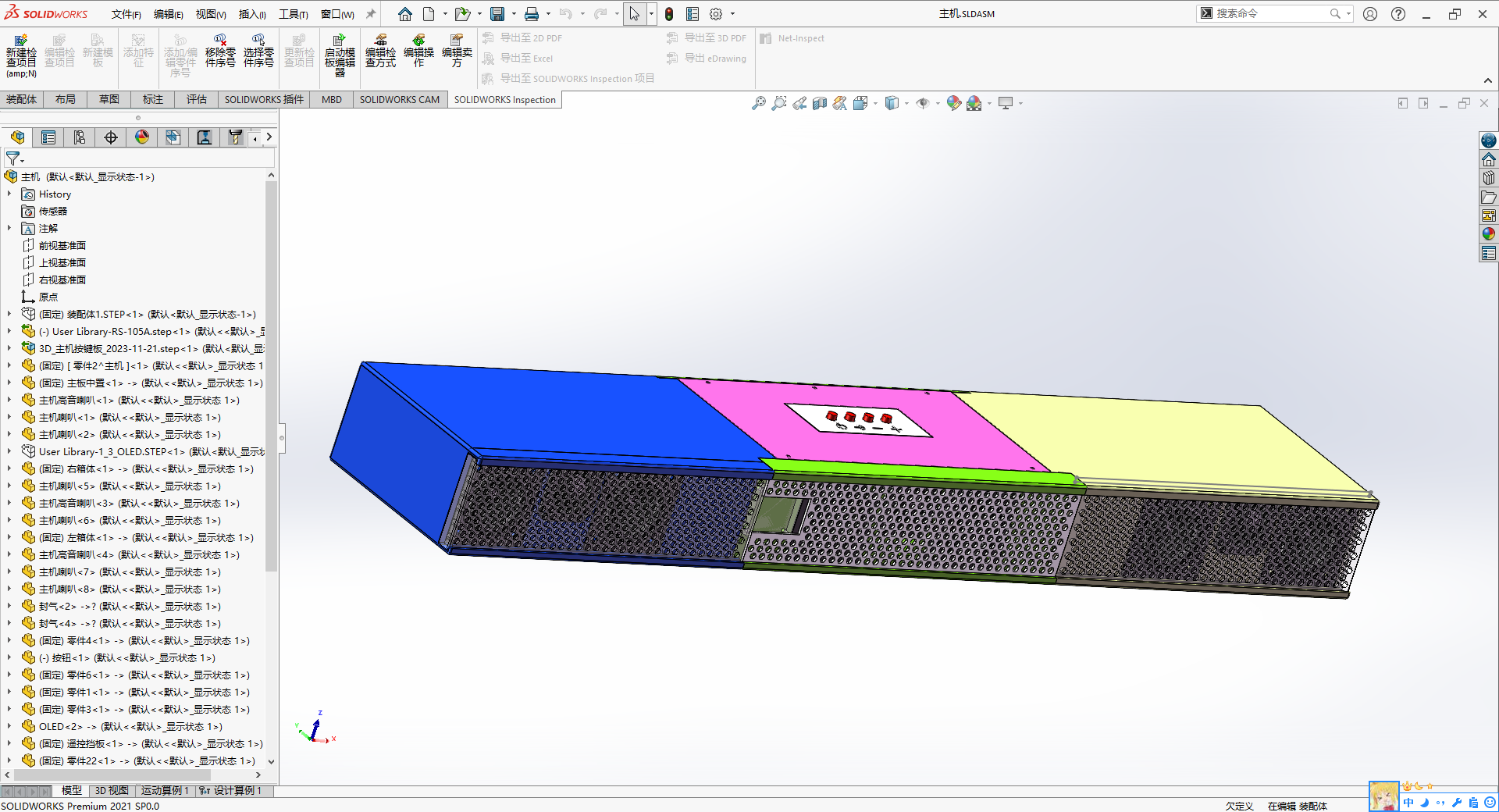
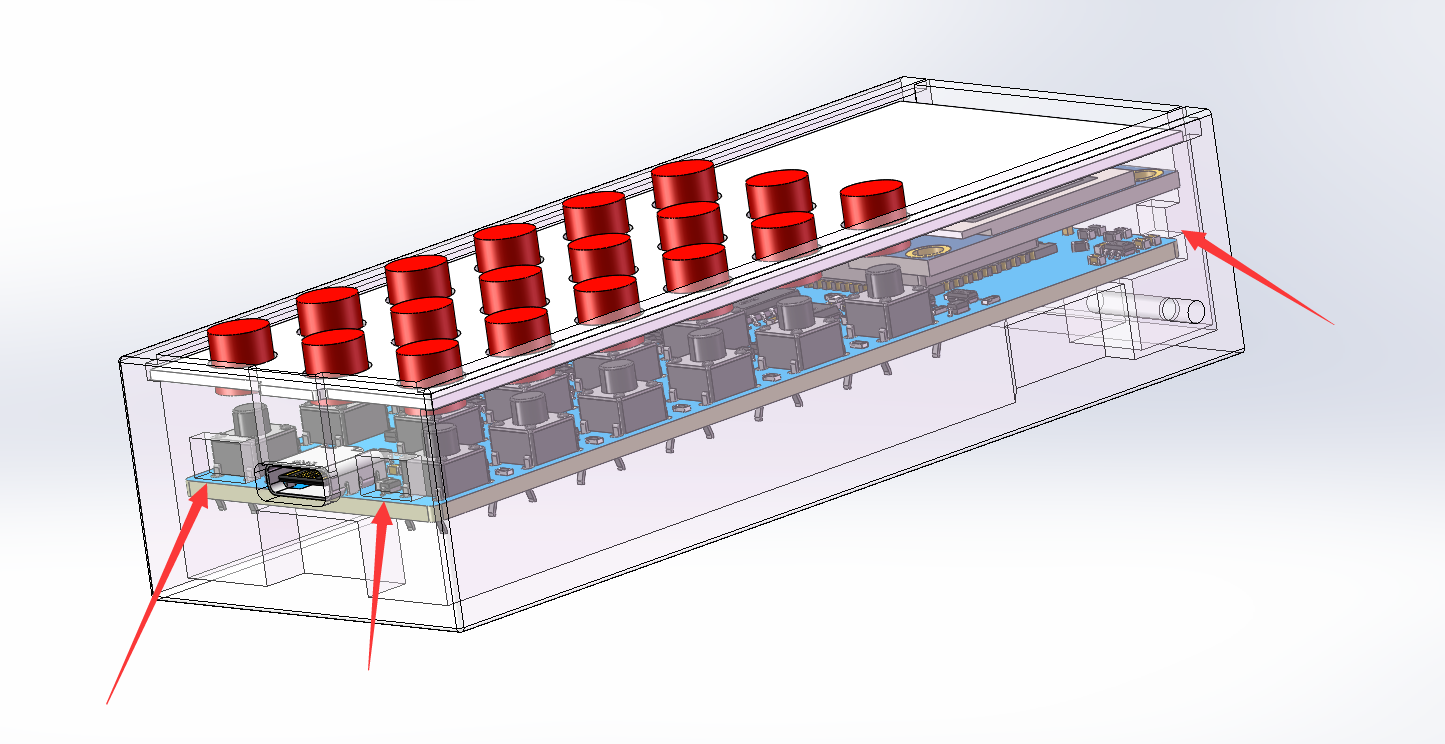
The overall design is a modular system, divided into left, center, and right sections, with basic symmetry.
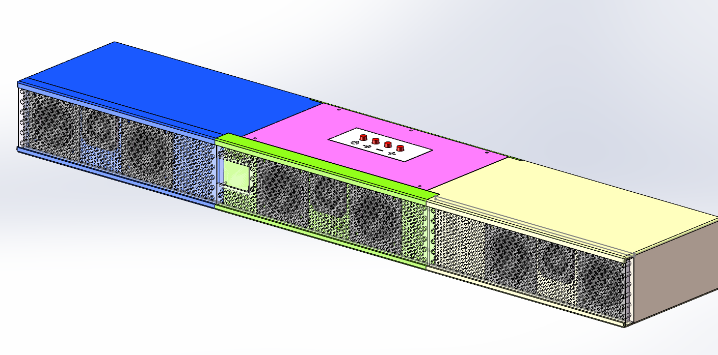
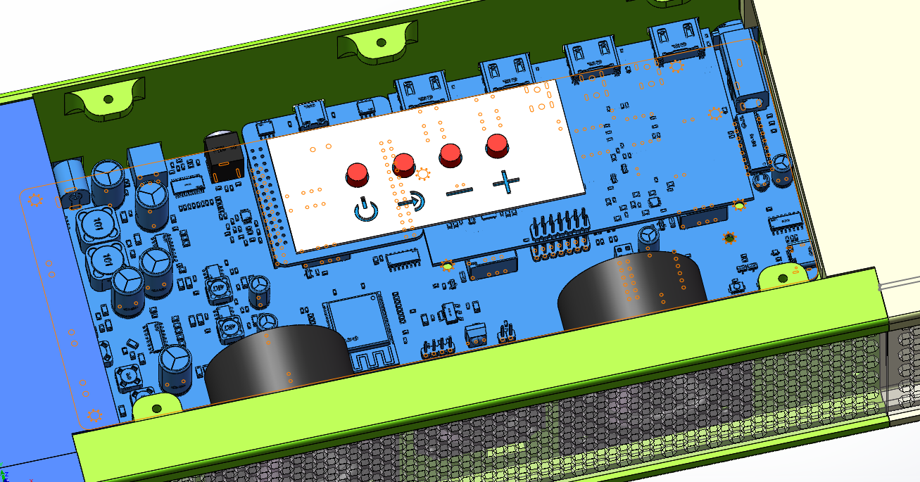
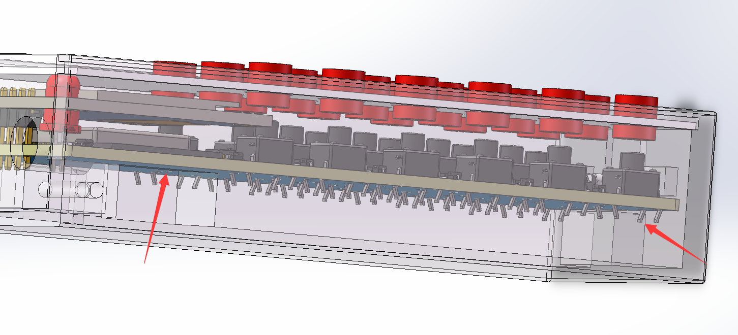
The mainboard is located in the center housing, and the button panel is above it.
A partition separates the housings, creating unused cavities. A groove on top allows for speaker wire routing.

The remote control and OLED screen are located at the front of the center housing.
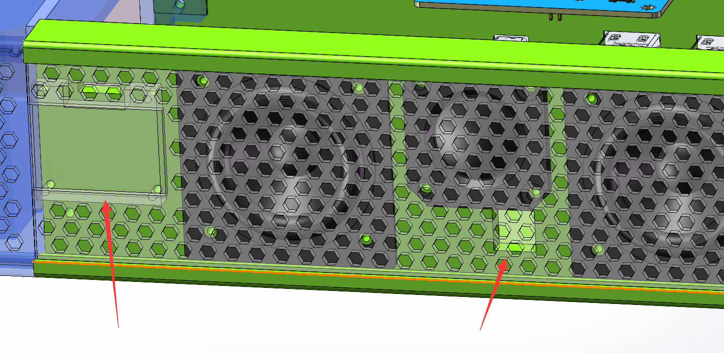
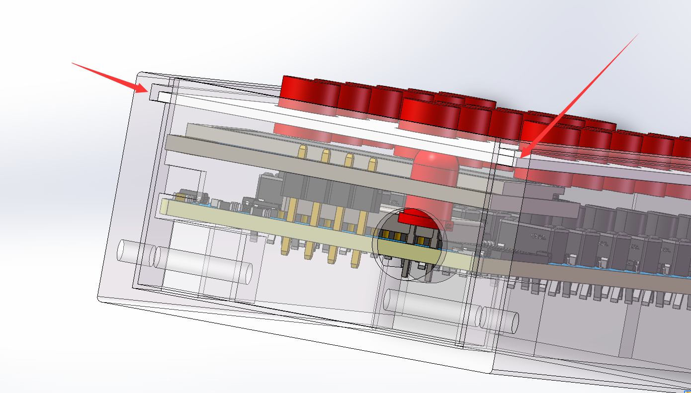
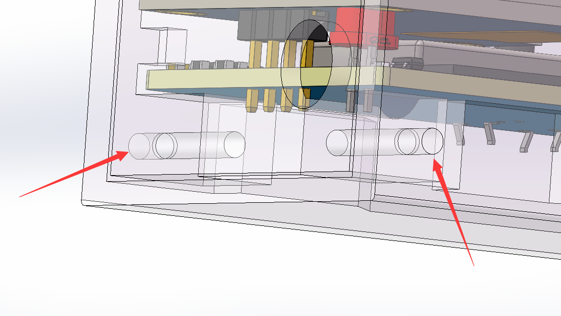
The front grille uses a sliding rail system, pushed in from the left or right.
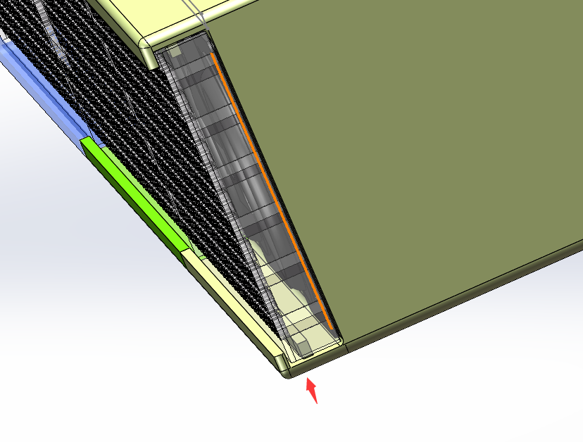
A fixing groove on top secures the front grille
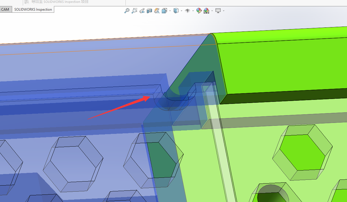
to the center housing, secured with screw posts

. The left and right housings require opening supports at a 2-degree angle

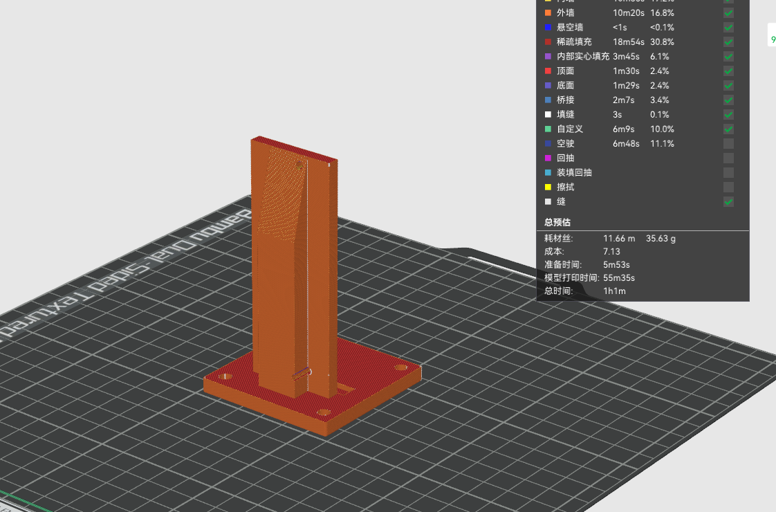
. The center housing is vertically printed; adding a rim is recommended to reduce warping. Support is needed at a 2-degree angle.

The top housing requires opening supports.

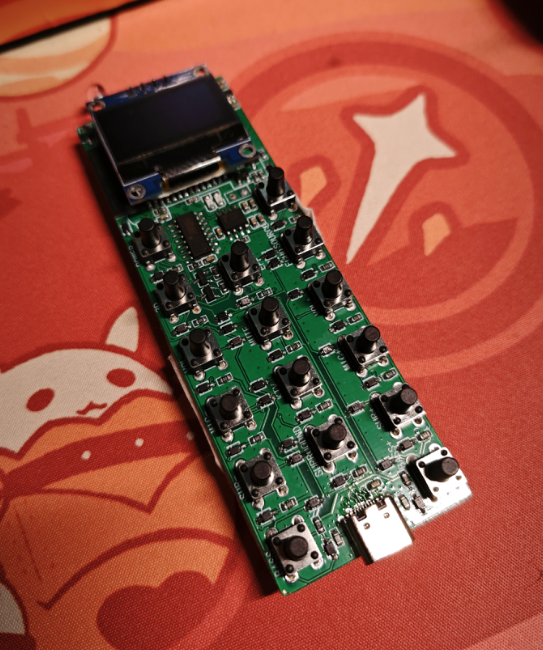
12.3 The remote control
is modeled as follows, with approximately 35g of material.
A panel, 1mm thick, is drawn between the PCB and the buttons.

The motherboard has front and rear supports, and the battery compartment below
has PCB mounting points at both the front and rear.
Acrylic plates are pushed in using rails.
The front panel is fixed with two screws;
the design avoids the need for supports and allows for vertical printing

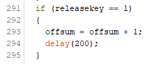
. 12.4 Surround/Subwoofer Rear
Terminal Panel Modeled as follows,
with approximately 35g of material.

The design avoids the need for supports and allows for vertical printing.
13. Panel Drawing:
After drawing the panel shell in SW, export the panel DXF file
and then import it into LCSC EDA to draw.
There are three panels: one is the front panel of the remote control, one
is the rear terminal panel of the main unit, and one is the panel used for sealing the remote control.
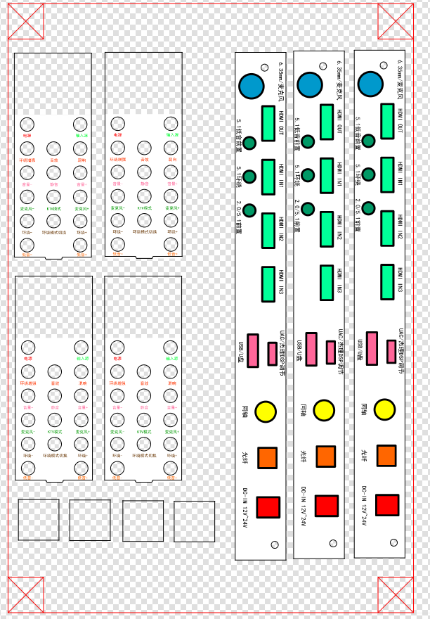
Actually, the top buttons of the main unit can also be drawn using panels, but I was lazy and didn't import and draw them; I used different colored 3D printers instead.

14. Assembly Material Preparation:
Subwoofer Wooden Box Purchase Link: Purchase link for a 6.5-inch empty wooden crate with a mesh cover :
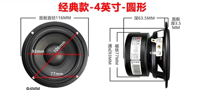
https://item.taobao.com/item.htm?spm=a1z09.2.0.0.42d72e8dsEoVc9&id=545298121416&_u=mqavhl8bf57 The veneer and grille are priced at 140 RMB. You can also choose not to use the ones I purchased. The rear wooden enclosure is universal; you can use any empty wooden enclosure you have. It's a 6.5-inch 4-ohm subwoofer. You can buy a cheaper one or a more expensive one. (Link: https://item.taobao.com/item.htm?spm=a1z09.2.0.0.42d72e8dsEoVc9&id=572032114334&_u=mqavhl8de94 ) https://item.taobao.com/item.htm?spm=a1z10.1-c.w4004-3466264636.16.268a3aa8NClHTo&id=520773948606 For better bass performance, try to buy this type of dome surround speaker, using 4 inches and 4 ohms. Round ones are available at varying prices. https://item.taobao.com/item.htm?spm=a1z09.2.0.0.42d72e8dsEoVc9&id=702903272639&_u=mqavhl8696e


https://item.taobao.com/item.htm?spm=a1z10.1-c.w4004-3466264636.10.268a3aa8NClHTo&id=38477426105
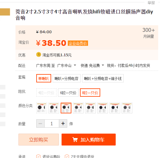
Buy full-range
surround sound tweeters, 3-inch 8-ohm.
https://item.taobao.com/item.htm?spm=a1z09.2.0.0.42d72e8dsEoVc9&id=671748016488&_u=mqavhl812dc
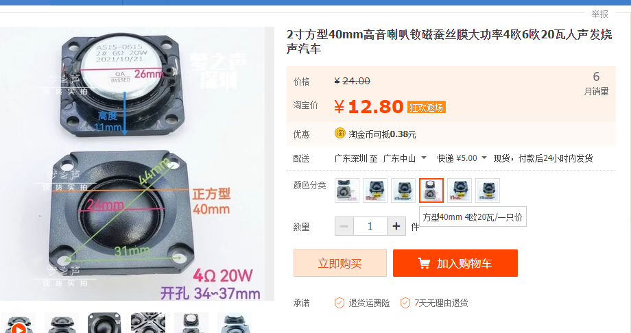
Main unit tweeters, 3 square 40mm tweeters. 4 ohms 20 watts
https://item.taobao.com/item.htm?spm=a1z09.2.0.0.55592e8dA5yLob&id=674968087619&_u=mqavhl8ba72
Buy 8 ohms 2-inch speakers for the main unit; you'll need 6 in total. You can buy cheaper or more expensive ones.
For the main unit speaker, pay attention to the 3D model opening; don't buy one that's too large, or you may need to enlarge the opening later.
[Links provided: https://item.taobao.com/item.htm?spm=a1z09.2.0.0.15012e8d9rHRLW&id=676057326677&_u=mqavhl88570 ] [Links provided:
https://item.taobao.com/item.htm?spm=a21n57.1.0.0.7675523c9q5IWR&id=536550064219&ns=1&abbucket=10#detail
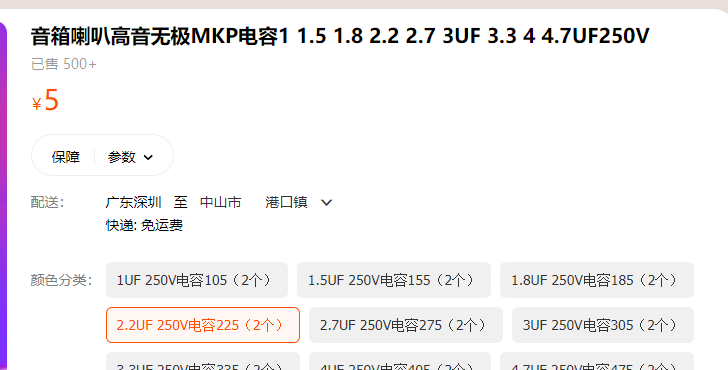
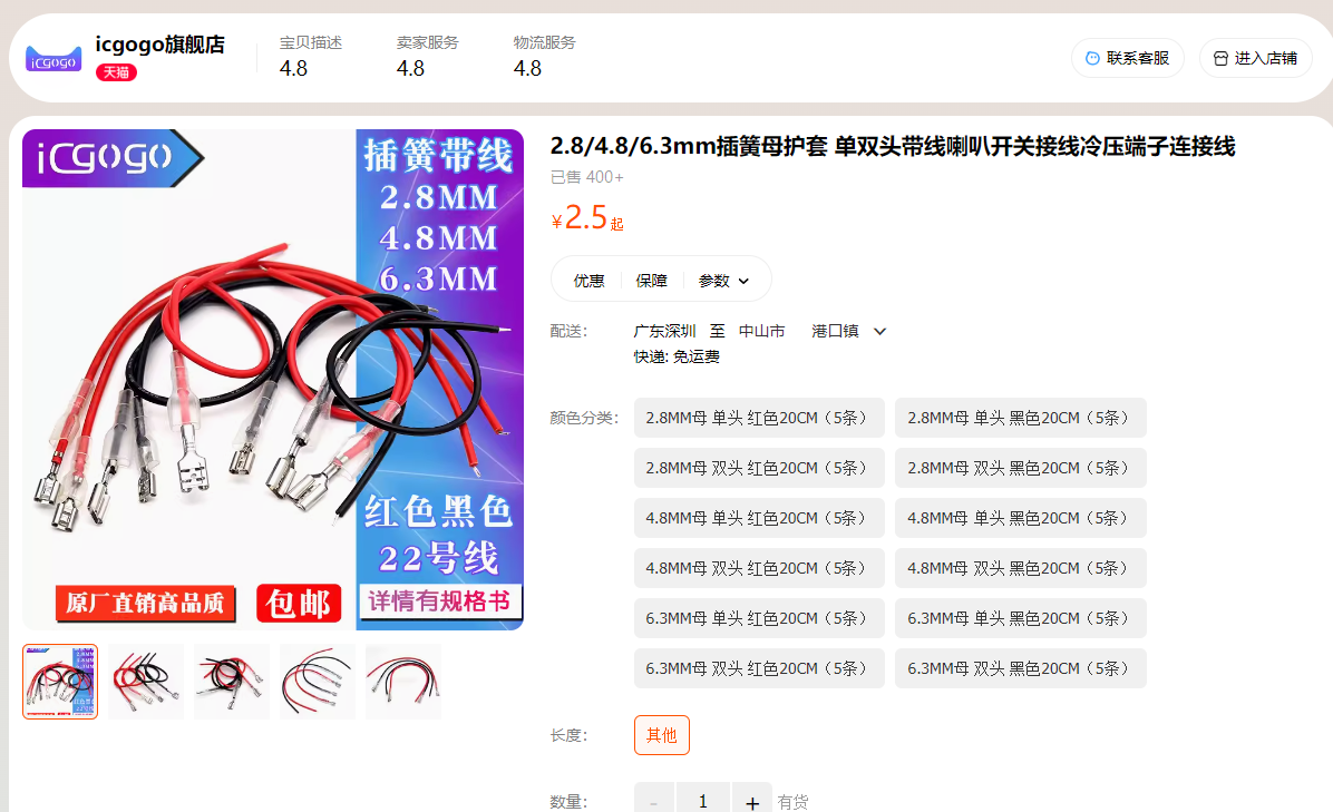
] Use MKP 2.2uf 250V capacitors for the tweeter crossover.
https://detail.tmall.com/item.htm?id=678361457770&spm=a1z09.2.0.0.42d72e8dsEoVc9&_u=mqavhl844b3
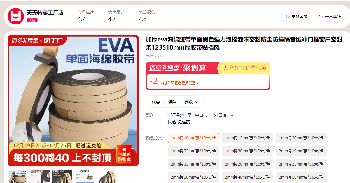
EVA cotton, for sealing purposes. Buy the cheapest 1mm roll; if it's not thick enough, apply another layer. I recommend buying two rolls. [Link 1
: https://detail.tmall.com/item.htm?_u=mqavhl8f001&id=740864800597&spm=a1z09.2.0.0.42d72e8dsEoVc9 ]
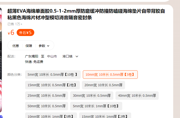
Sound-absorbing sponge, 1mm thick, is for wrapping cables to prevent vibration. [Link 2:
https://detail.tmall.com/item.htm?abbucket=20&id=645815964629&ns=1&skuId=4660038213857&spm=a21n57.1.0] 0.144e523cMMoxe5
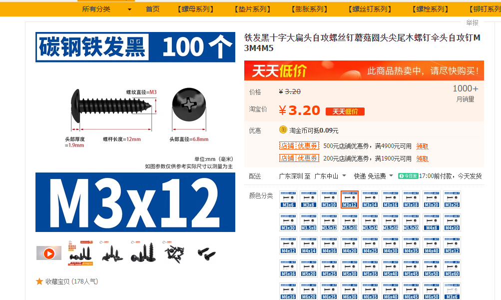
self-tapping screws
https://item.taobao.com/item.htm?spm=a21n57.1.0.0.224e523cEAvnF5&id=600824489026&ns=1&abbucket=20#detail
Sound-absorbing cotton to improve standing waves
https://item.taobao.com/item.htm?spm=a1z09.2.0.0.42d72e8dsEoVc9&id=537824839025&_u=mqavhl85960

Remote control batteries: Sizes [502080-1000 mAh] Surround sound module:
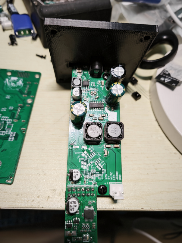
https://item.taobao.com/item.htm?spm=a1z09.2.0.0.42d72e8dSWwgbp&id=602110158806&_u=mqavhl8201f Wireless subwoofer module: https://item.taobao.com/item.htm?spm=a1z09.2.0.0.42d72e8dSWwgbp&id=564378077571&_u=mqavhl87a3b This link ( https://item.taobao.com/item.htm?spm=a1z09.2.0.0.42d72e8dSWwgbp&id=562298037019&_u=mqavhl88e6c ) lists a wireless microphone. A cheap one is fine; a wired connection is also possible (this particular wireless microphone is actually a Bluetooth connection). [Link 1] Copper pillars, M3*11+5, for fixing the HDMI board and motherboard. [Link 2] Copper pillars, M3*11+5, for fixing the HDMI board and motherboard. M.3 nuts : https://detail.tmall.com/item.htm?_u=mqavhl89ecc&id=579434930761&spm=a1z09.2.0.0.67002e8dubVAY2 Self-adhesive rubber feet for attaching to wooden crates and main unit: https://item.taobao.com/item.htm?spm=a1z09.2.0.0.67002e8dubVAY2& The speaker wire connector ( id=626062804142&_u=mqavhl8e113) can be omitted; you can solder it directly with wire. [https://detail.tmall.com/item.htm?abbucket=20&id=664514304205&ns=1&spm=a21n57.1.0.0.1c82523cEg261h&sku_properties=122216547:20213 ] 1.3-inch OLED: https://item.taobao.com/item.htm?spm=a21n57.1.0.0.5635523c826xjG&id=562145367495&ns=1&abbucket=20#detail Switch button caps (3.1mm inner diameter): https://detail.tmall.com/item.htm?_u=mqavhl87b00&id=627223991084&spm=a1z09.2.0.03d932e8ddnv2tJ&skuId=4446877365580 15. Surround/Subwoofer Assembly: Assemble the surround speaker as follows: Install the surround board on the rear terminal block and insert the wireless module.


The positive terminal of the tweeter is co


 京公网安备 11010802033920号

 VP16256-40


