Project Description:
This multi-functional camping light serves as both an ambient light and a general illumination light. Utilizing an IP5328P+STM32+WS2812+BLE structure, it brings you a warm glow in the night.
I prefer to call it "glow" for short, hoping it can bring you a touch of warmth with its glow every night.
Project Replication and Construction Instructions:
This project involves numerous PCBs, 3D parts, and assembly accessories, making the assembly process quite complex. The instructions in the open-source project may contain omissions. If needed, I will release instructional videos to answer questions later (I'll be waiting for that!). If you have any questions, please comment on the project or join the QQ group for discussion. Please try to avoid using private messages on this platform (they're easily missed).
QQ Group: 1016193632.
Welcome to follow my Bilibili account: @何电工.
Project videos and future videos will be released on my Bilibili account. Thank you for your attention!
This project documentation is quite long. If you're just looking for design references, you can only read the relevant sections and the datasheet (attached).
If you plan to replicate this project, please read it all patiently. If you have any questions about my design or program, please read the project description and datasheet first (reading the datasheet won't hurt).
Let's begin with this background music.
Open source license :
CC BY-NC-SA 3.0
(Creative Commons Attribution-NonCommercial-ShareAlike) 3.0)
Main Functions
: The camping lamp uses COB filaments and 3D printing to construct an exquisite spiral line.
It uses an IP5328P as the main power controller, supporting bidirectional PD fast charging and PPS output.
The battery compartment structure is compatible with 26650 (non-replaceable) or 21700/18650 (replaceable). The battery
uses WS2812 LEDs to form the top light ring, enabling dual functions as a lighting and ambient light. It
communicates with the STM32 and 5328 via I2C to obtain charging and discharging data, and transmits this data via BLE.
It connects to a mobile app via BLE for handheld control of the "flying lamp" (currently has some bugs).
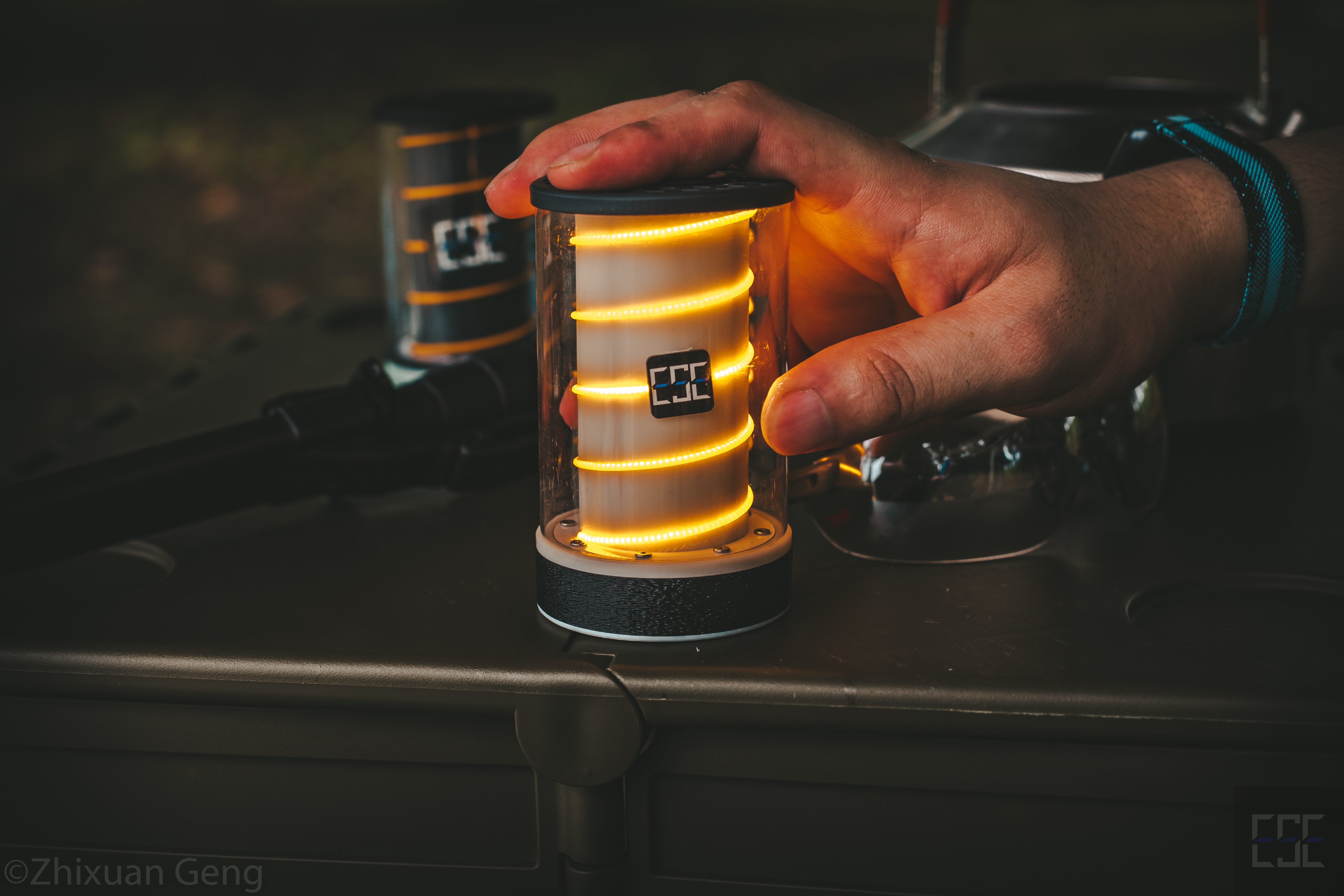
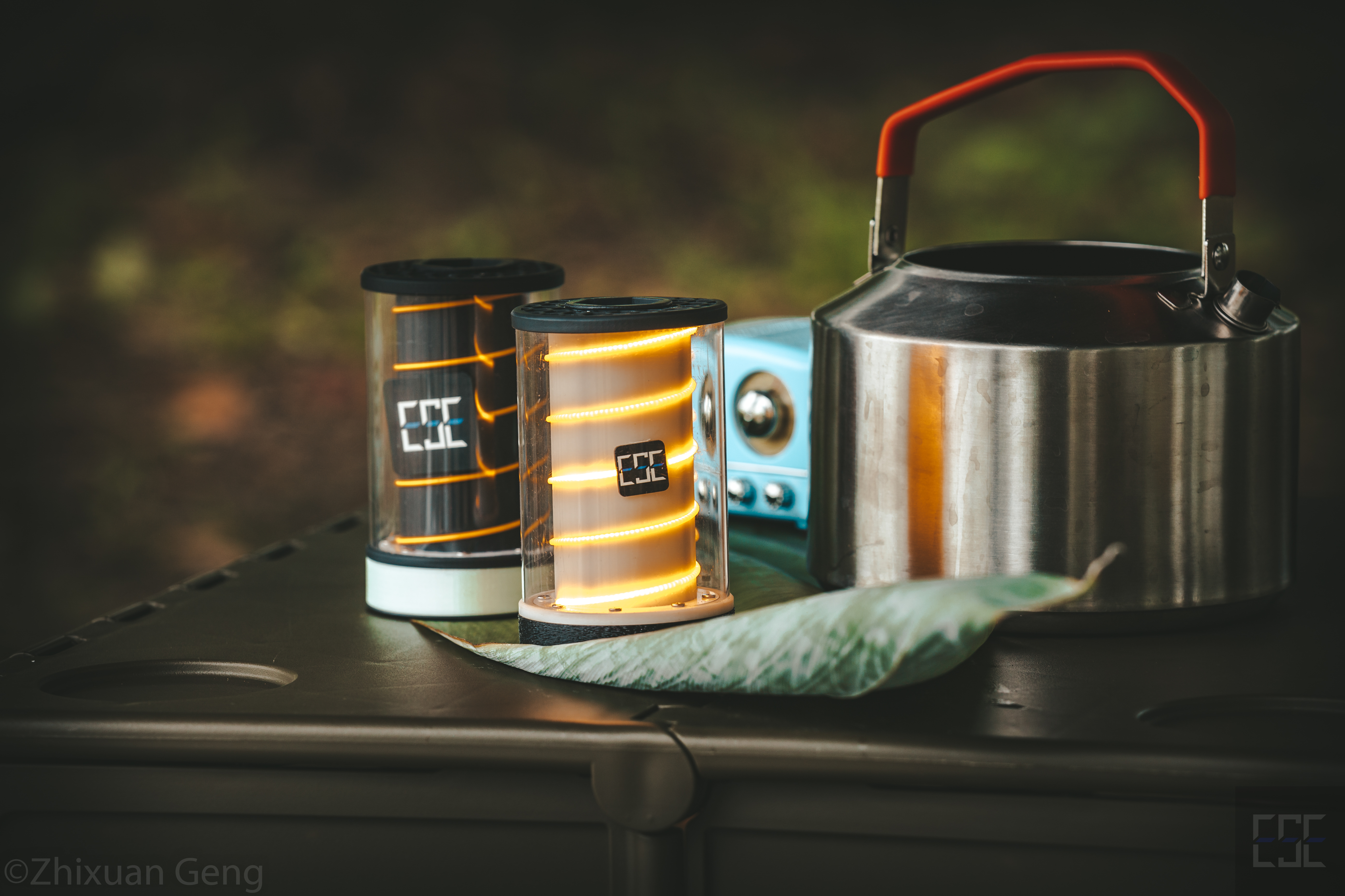
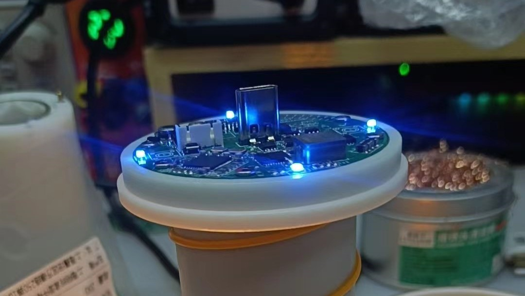
Lighting effect ↑
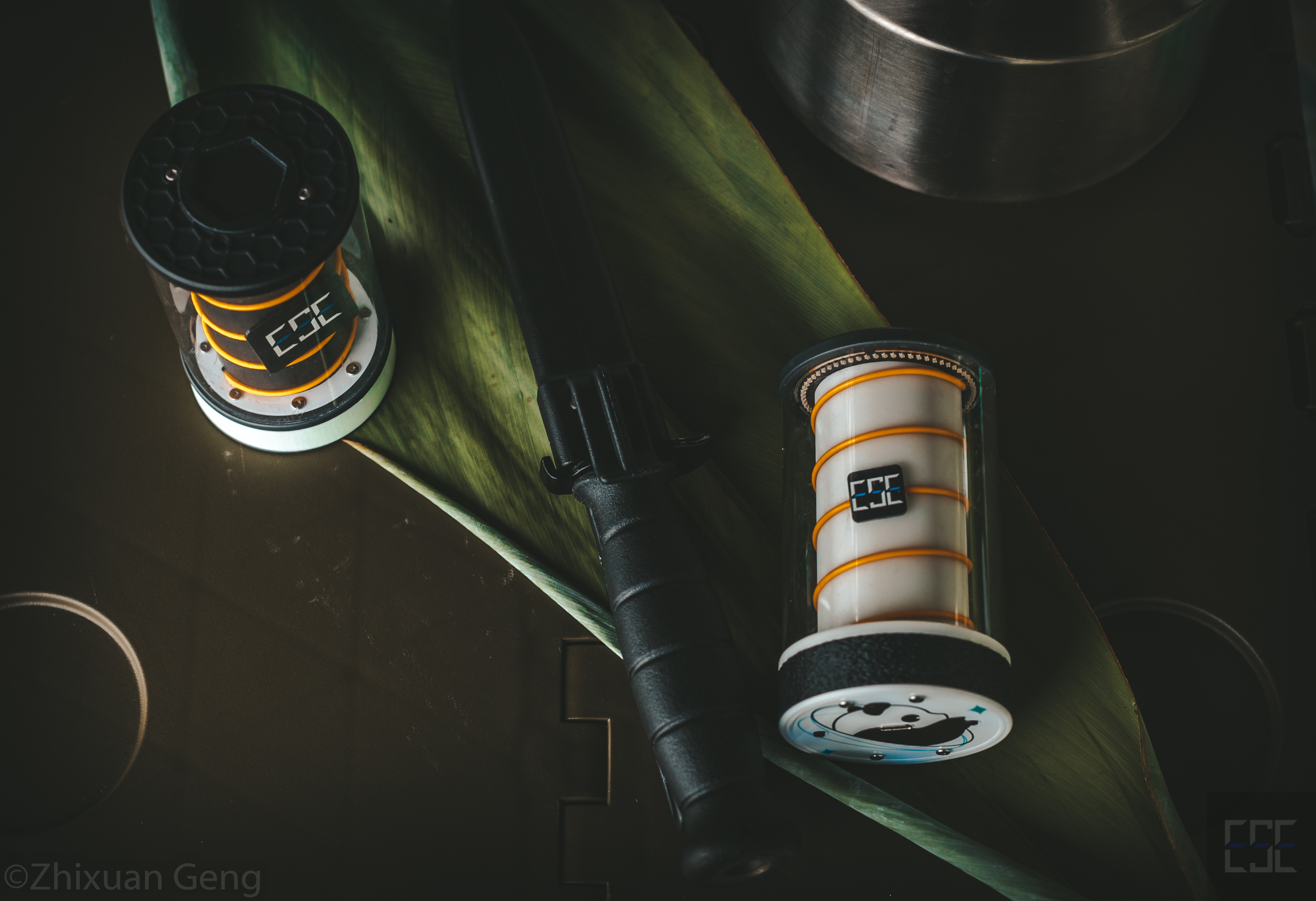
Still life effect ↑
Note: Other items besides the camping lamp in the photos are film props.
Project Attributes:
This project is being publicly disclosed for the first time and is my original work.
This project has not won any awards in other competitions.
Hardware Specifications:
Please note that this project consists of four PCBs: two 4-layer boards and two 2-layer boards (all within 10*10mm can be prototyped free of charge).
The hardware specifications will be written based on the PCBs to facilitate understanding of the circuit design; it is recommended to read them in conjunction with the circuit diagram.
Replication precautions will also be provided in this section for reference .
I. Mainboard:
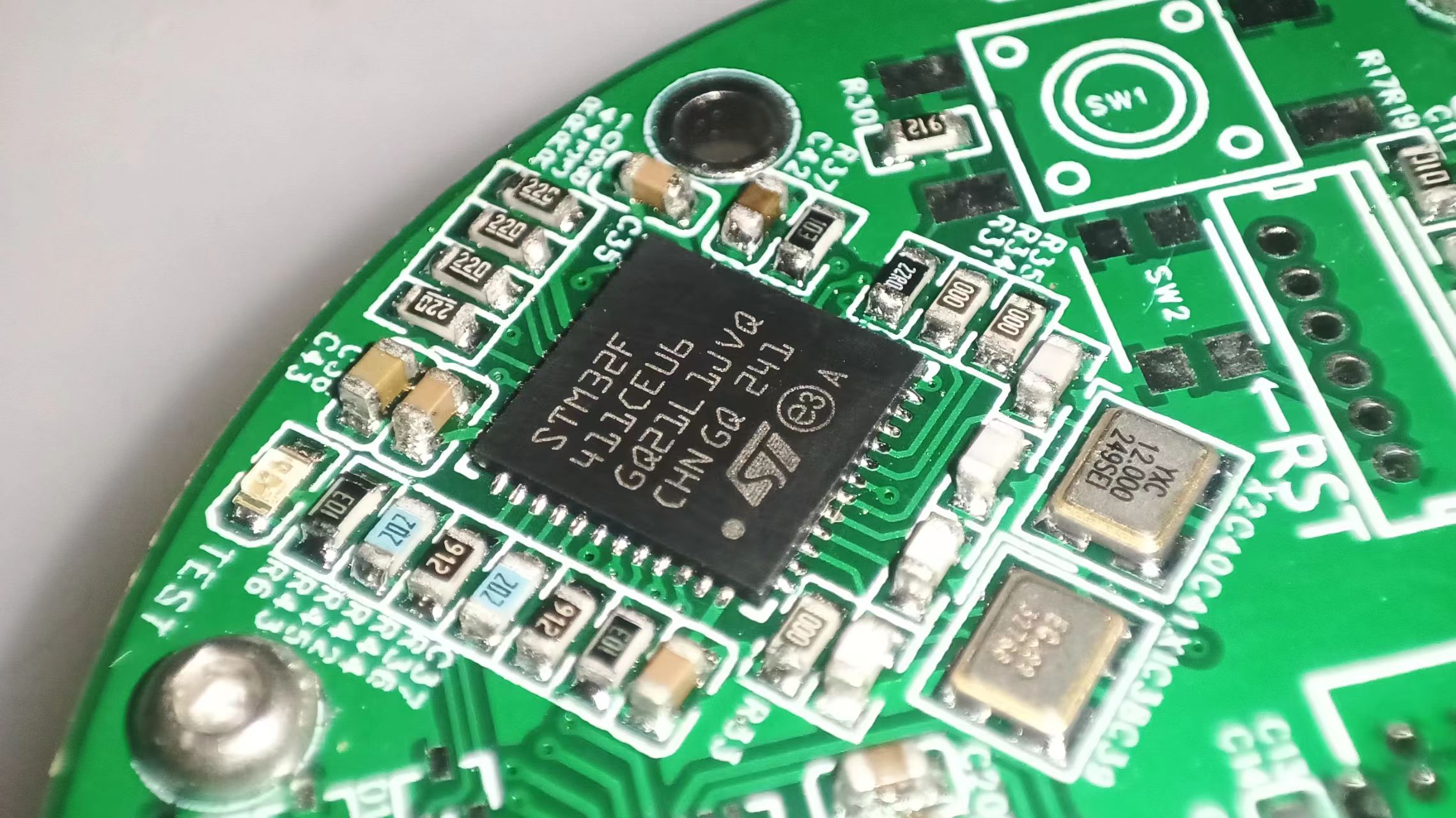
The mainboard is responsible for housing the IP5328 power bank circuitry and the STM32 main control circuitry. It uses jumpers and copper pillars for external connections (the PCB shown in the image below is the mainboard PCB).

1. Microcontroller Main Control and Peripheral
Circuits: The main control microcontroller uses an STM32F411 microcontroller to ensure sufficient expandability.
This part of the circuit mainly includes the F411 microcontroller as the main controller, external debugging interfaces (using 1.25mm pitch connectors, including an SWD debugging interface + serial port for convenient debugging, and a reset pin for remote operation), an external FlashW25Q128 chip (but it was not used in the later program and can be left unsoldered; it can be used for future program upgrades), a BT-11 Bluetooth BLE module, a buzzer, etc.
The ports connecting the microcontroller and IP5328P are all protected by series resistors, and additional ESD protection devices are added to the external interfaces (of course, you can also choose not to solder
the microcontroller). Using SWD for downloading and not using DFU, BOOT0 and BOOT1 are grounded with 10K resistors, which can also be shorted and pulled up when needed.
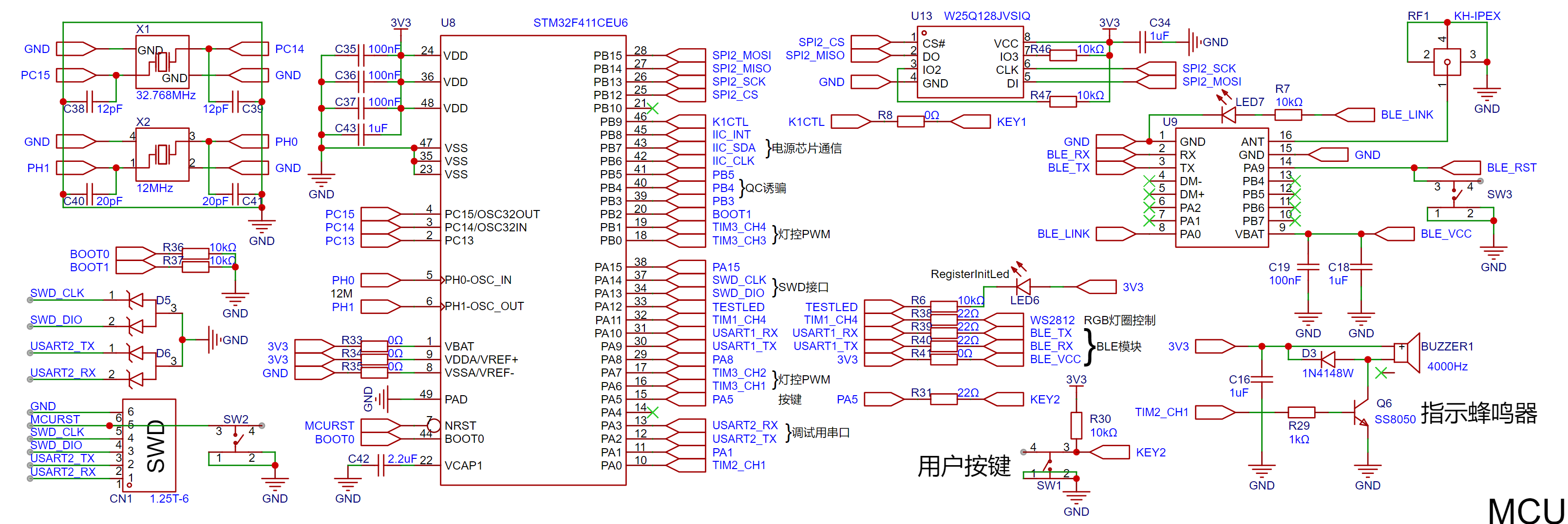
The crystal oscillator part of the BOOT pin does not need to be soldered and is not used. Note: Originally, G... 0. However, the earliest program for the WS2812 used an array-brushing scheme, which required a large memory capacity. Therefore, it was later replaced by the F411. Later, an RGB to HSV scheme was adopted. The HSV scheme not only has a better display effect but also occupies less space. However, since the PCB design was basically finalized at this time, it was not replaced with G0. The disadvantage of this is that the project cost is relatively high, but there are no other problems.
2. IP5328 Charge and Discharge Management
This project uses IP5328P as the main controller for the charge and discharge management section.
IP5328P also undertakes the functions of a power bank and a boost power supply. The power bank function is used for external output and charging of the internal battery, while the boost output is linked with the microcontroller program control to provide high-power power to the fluorescent filament and WS2812. I also reserved VOUT2 (currently unused) so that everyone can expand more functional circuits according to their own needs.

The circuit design of the charge and discharge management chip IP5328P mainly refers to the official I won't go into the details of the datasheet here.
For the 22uF capacitor, I chose the relatively expensive TDK "HiFi capacitor" for its high voltage resistance. You can replace it with other capacitor models according to your voltage requirements.

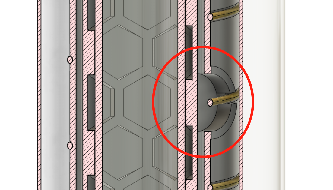
On the back of the main control board (in the sandwich between the main control board and the adapter board), you need to solder a solid capacitor. The
recommended capacitor model is E2221M025A120RL (LCSC component number C2898868). It has been shown in the circuit diagram.
This capacitor has a diameter of 5mm, which is very suitable for laying flat and placing in the sandwich (the soldering diagram is shown on the PCB, and the actual soldering effect is shown in the picture below).
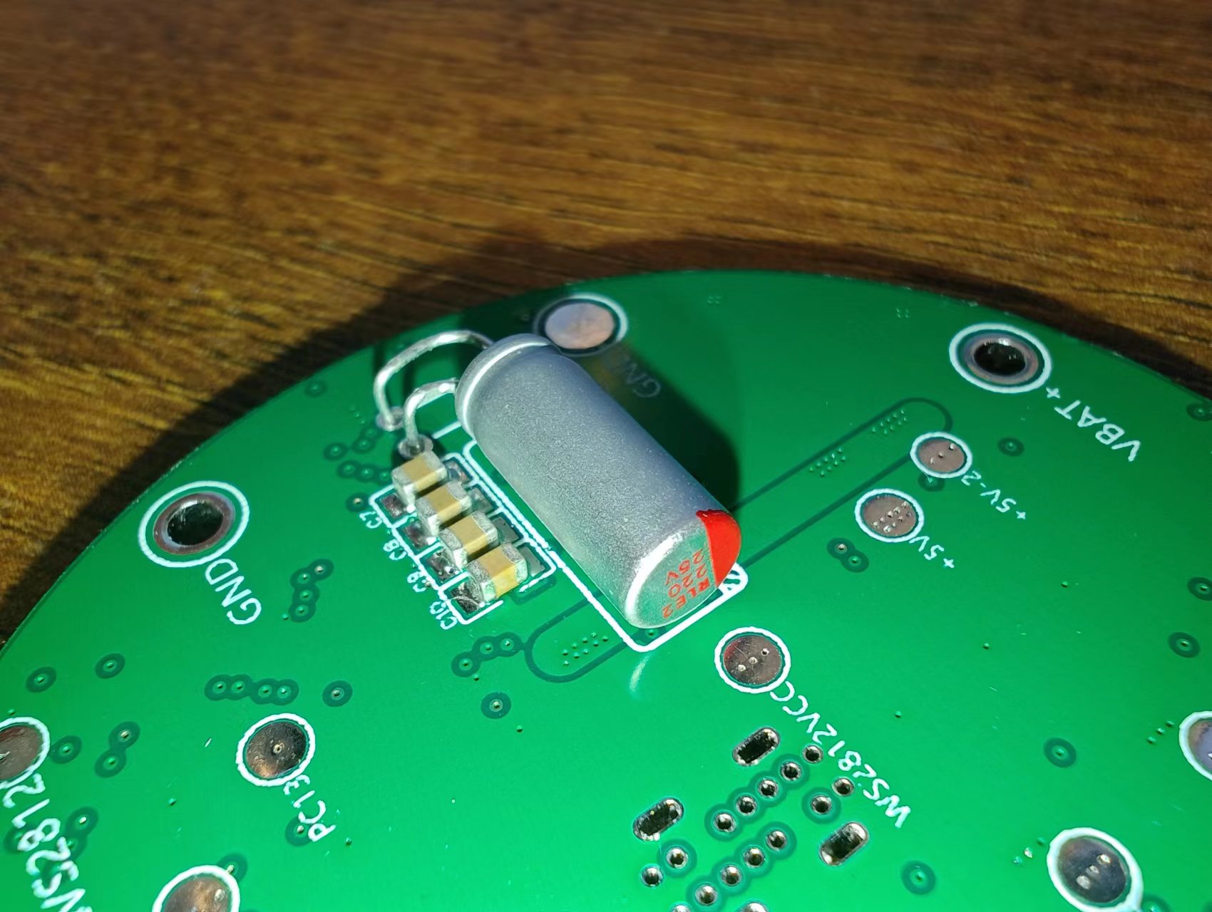
Note: If you need to replace it with a different type of capacitor, you need to make sure that the capacitor diameter does not exceed 5.5mm, otherwise it will not fit in the sandwich.
To accommodate the motherboard with the ring, the four power indicator lights also adopt a ring layout, which is more aesthetically pleasing
and can also light up the decorative ring (if a luminous or translucent material is used). When replicating, you can choose an appropriate LED according to the color of the decorative ring to achieve different lighting effects. The same color effect can be achieved by configuring different current-limiting resistors according to the actual light transmission and illumination conditions.
The power input interface uses a vertical Type-C interface, 14P version, 10 or 10.5mm in height.
Of course, if you need an interface of other heights, you will need to modify the decorative ring/luminous ring and the height of the studs yourself.

The Type-C shell pads are difficult to solder. It is recommended to use a hot air gun to heat while soldering (the recommended temperature of the hot air gun is 280-300℃, do not exceed 320℃ for a long time, otherwise it is easy to burn the PCB, don't ask me how I know). I have enlarged the GND pads in the new version of the PCB to facilitate soldering.
After soldering, you need to check carefully to prevent short circuits (I have only experienced this once, because it is easy to brittle).
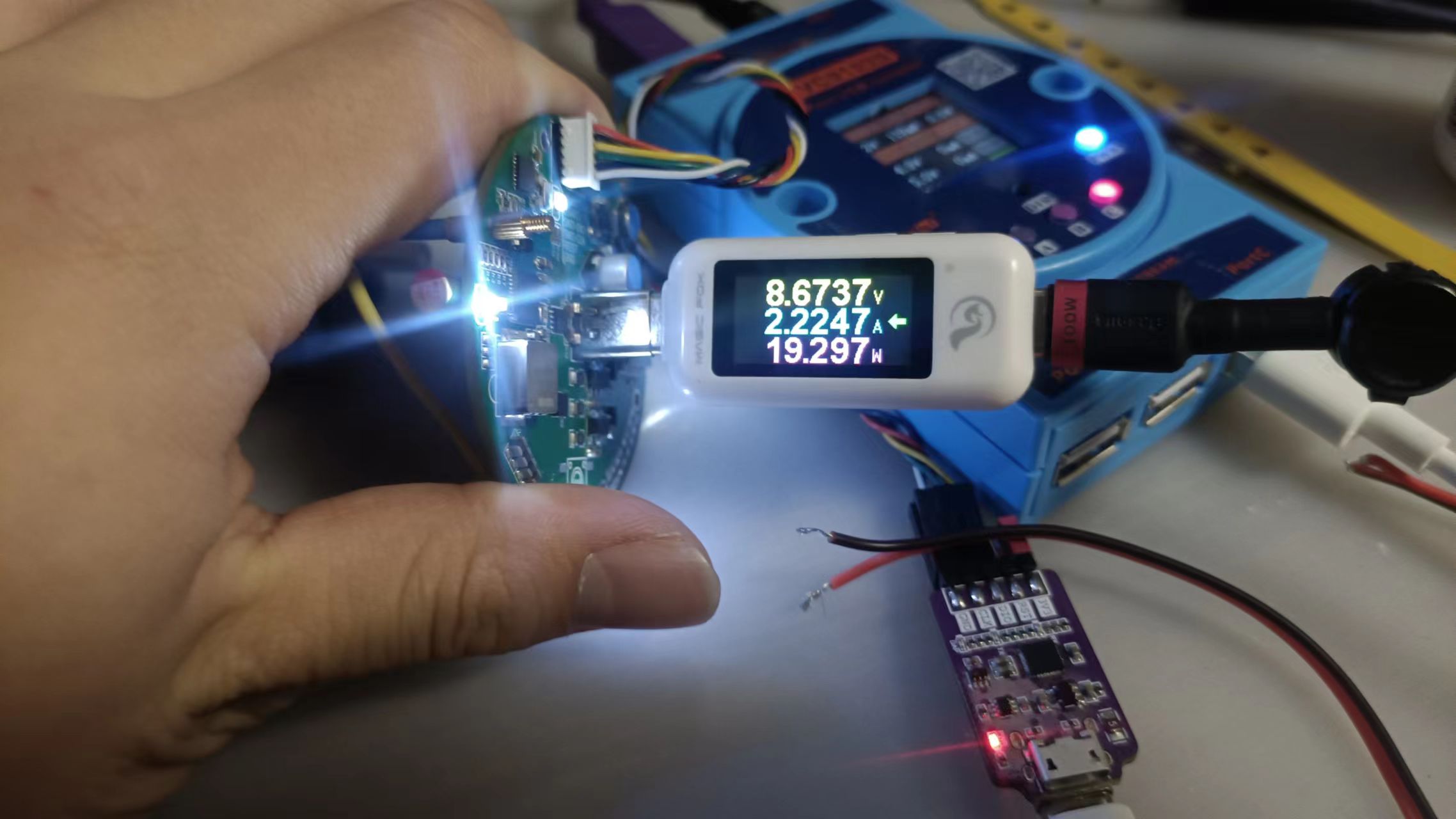
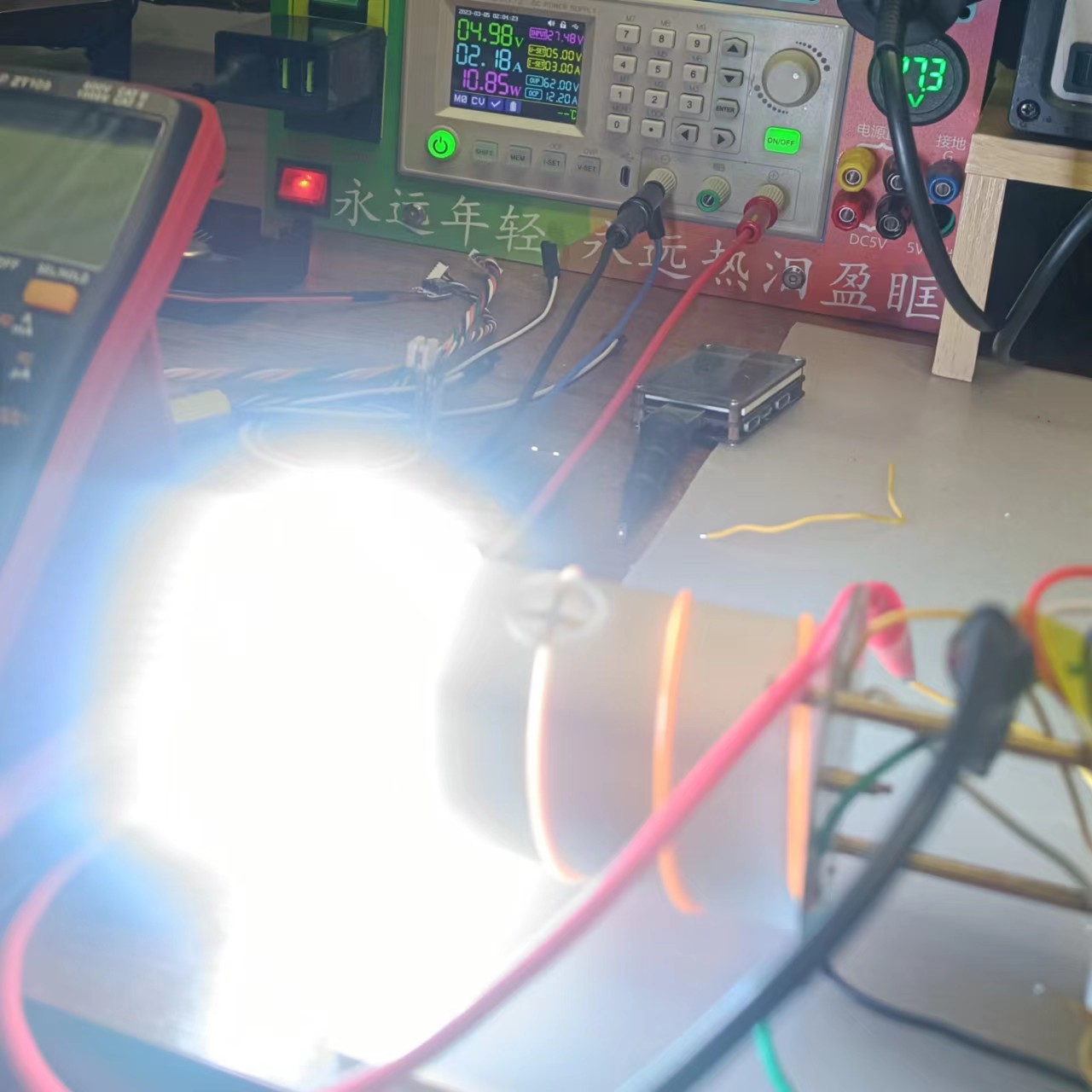
Testing charging and discharging only requires soldering the IP5328P and related peripheral components, which is unrelated to the microcontroller, as shown in the figure below.
At this time, you can test the "charging and discharging management minimum system" for easy repair if there are any problems.
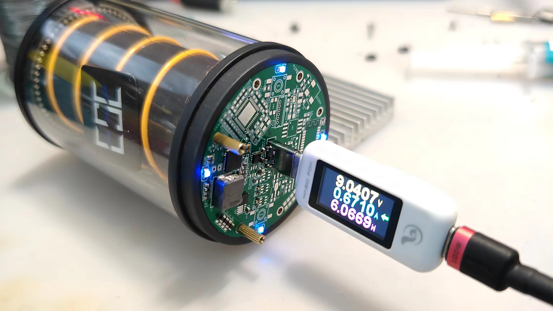
The measured maximum charging power is close to 20W.
The maximum power output is 23W, which is relatively low. In most cases, it will remain around 14W.
The tested supported charging protocols are as follows:
Please refer to the chip's datasheet for specific protocols. The test results are for reference only.

3. The control of the "lamp":
The filament and power supply section of the WS2812 are as follows (including the filament dimming control circuit):

The boost (BAT to 5V) output section uses MOSFETs for control. The MOSFETs can be controlled based on the basic control logic of the 5328, or they can be controlled using a microcontroller via I2C communication and register manipulation.
It should be noted that the 5328 has fast charging input/output functionality, and the VMID bus voltage is a maximum of 12V. Therefore, in the microcontroller program, the registers will be read to determine if the 5328 is in fast charging power bank mode. In this case, the MOSFETs will be forcibly shut down to prevent high voltage input to the "lamp" section and to prevent damage to the P. The WM controller and 2812 LEDs are used, but considering potential bugs or program crashes, an LP5300B6F overvoltage protection chip was added to protect the downstream circuitry. (I have to complain about the LP5300B6F's pin design; it's really ridiculous. Why are four out of six pins designated as GND, while only one is assigned to the input/output? The GND pins don't handle large currents at all; the entire current path is through the input/output. I can only suspect this design is for compatibility with other chips.)
Note: The "bottom LED ring" output shown in the image above is currently unused; it was just a project I initially planned (I also wanted to add a ring-shaped flashlight function at the bottom).
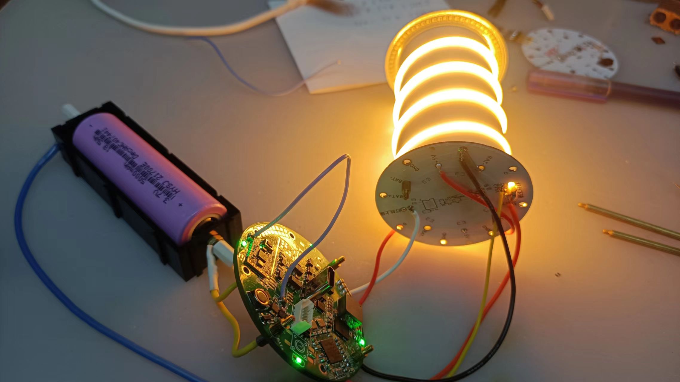
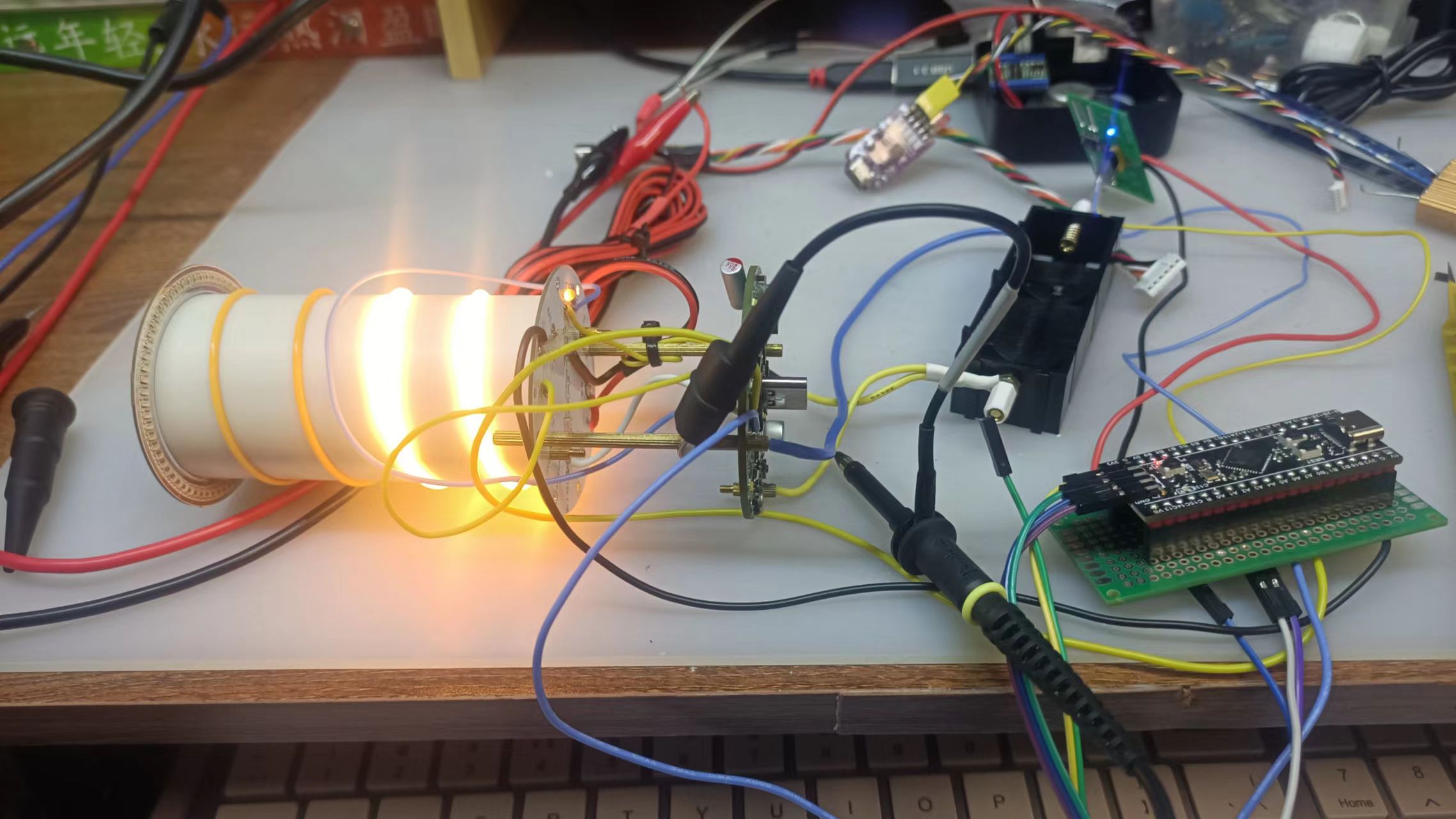
The filament can be tested directly on the motherboard without needing a separate PCB. Testing the actual lighting effect of the filament before assembly is recommended to prevent rework

.
4. Microcontroller Power Supply:
The power supply for the microcontroller and Bluetooth section is achieved through the RT6150 chip, which automatically boosts and bucks the battery voltage to achieve a regulated 3.3V output
. Note: This chip has recently increased in price (more expensive than the 5328 main controller, which is a bit outrageous). You can replace it with another boost/buck chip.
The PS pin of the RT6150 chip is used to control the PSM operating mode; please refer to the datasheet for specific effects.

After soldering the motherboard and main unit board, it is recommended to use long studs for testing (this ensures electrical connection while allowing the use of a multimeter). 1. Use oscilloscope probes to test key nodes; otherwise, it will be impossible to test the electrical nodes on the back of the main control board after all assembly is complete.
You can first use a USB multimeter or other devices to test whether the charging function is normal, and then test other functions.

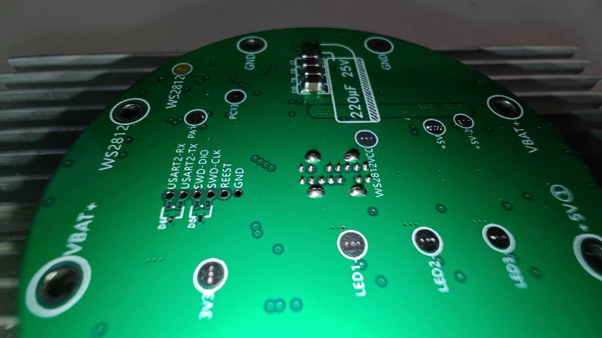
2. The main battery protection board (connection board)
is mainly used for battery connection, and at the same time, it prevents reverse connection and over-discharge.
The surface of the main battery lower board is designed with two arc-shaped solder pads for welding the connection spring of the positive terminal of the battery.
When welding the spring, it is recommended to add more flux and use a horseshoe-shaped or other large hot soldering iron tip to ensure stable connection of the spring.

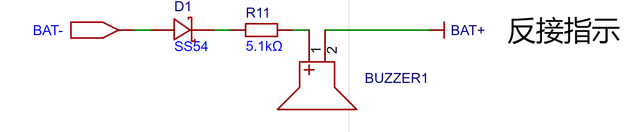
A very simple reverse connection indicator function was designed. When connected in reverse, current flows through the diode, causing the buzzer to sound an alarm directly. It's simple and clear.
All other pads and screw holes are labeled for easy wiring and soldering.
III.
Upper Lamp Board: As the name suggests, this is the upper-level lamp board, mainly responsible for the following three functions:
1. Battery Negative Terminal:
Connects to the battery compartment cover via a ring contact, thus enabling battery conduction

. To ensure good contact, it is recommended to tin this ring contact.
Key point: "Tin build-up".
2. Upper Filament Connection
: The solder pad with the filament negative terminal is provided. Insert the filament through the opening, and then solder (flatten the upper filament negative terminal and solder it to the oval pad corresponding to "Upper LED-"). Note that you should not solder to the through-hole pad; that is for soldering the connection wire to the base plate (silicone wire or long copper wire can be used).
The assembly method is shown in the following diagram:

3. The RGB ring light board
is designed with 64 WS2812 LEDs in 1010 packages
. As we all know, 64 is an integer, which makes programming easier. (

The photo doesn't do it justice; please see the attached video for a demonstration of the WS2812's performance.
Thanks to JLCPCB SMT for soldering the light board (the image below is the 2020 version, but due to high heat, it has been replaced with 1010 LEDs).

Here's a real photo of the WS2812-1010; it looks really nice
. (If you want to solder it yourself, I recommend using a constant temperature heating table, not a hot air gun, as hot air guns can easily cause the LEDs to change color, which looks bad).

The highest brightness test of the light board shows
that at full power (all three colors at maximum brightness, displaying white), the power is 10W+. Therefore,
it is not recommended to run at full power for a long time, as it is prone to overheating. )
4. Negative electrode spring connection board
: This seems to be self-explanatory. Connect the spring (soldering precautions are the same as for the spring on the adapter board), then glue it to the top cover.
To ensure good contact, the ring contact needs to be soldered.
V. The bottom cover
is made using LCSC panel printing, with a board thickness of 1.0mm. No adhesive is required
. The images used in the following bottom plates (except for the three-and-a-half-circle logo in the center) are all from the internet and are used only for decorative purposes. They are not for sale or profit. If there is any infringement, please contact me to delete them. Thank you.
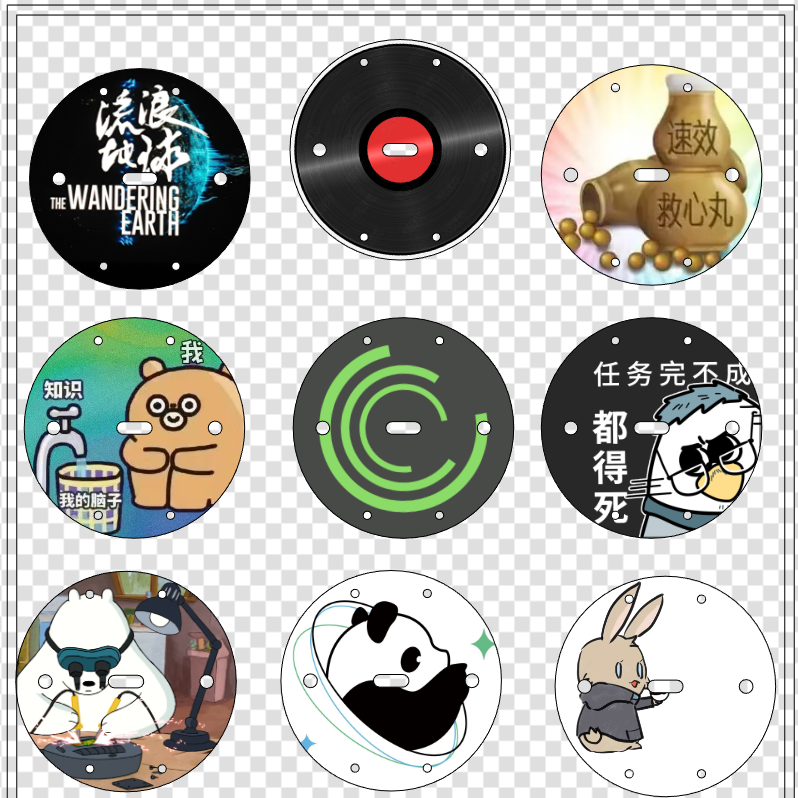
Below my design, I have also left a blank board frame. You can insert your favorite pictures to create a personalized bottom cover.
Software Instructions
I. Overall Software Description (Introduction) The software
communicates with the STM32 and 5328 via IIC to obtain charging and discharging data, and transmits it via BLE after packaging.
The charging data is the charging status of the "Fluorescent" night light by the external power supply.
The discharging data is divided into USB The discharge status of Type-C and the power consumption of the lighting section
are controlled by STM32 to control the filament and WS2812.
BLE connection to a mobile APP enables handheld control of "YingHui".
II. Embedded System Software
The embedded software description will be written according to the software tasks to facilitate program understanding.
The software code is in the project attachment compressed package!
1. Initialization Task 1.1. Change Bluetooth Name
You can modify the Bluetooth name according to your needs. The default name of the Bluetooth module is BT-11, and the default name of the program initialization is YingHui. 1.2. Wait for the power control chip to be activated
If the battery is inserted for the first time, charging activation is required.
If charging activation is complete, the microcontroller will reset; then click the power button to activate. 1.3. Activation Successful Indicator Light
The indicator light below the microcontroller is labeled INIT.
If a glow-in-the-dark ring or other translucent material/color decorative ring is installed, this indicator light can be removed after debugging. 1.4. Delete Initialization Task
2. Functionally, the watchdog timer allows the microcontroller to return to the state it was in when the program encounters an unexpected event (entering an infinite loop or crashing), thus ensuring that the system can be restarted once if a problem occurs. To put it simply, a watchdog timer is a mechanism that can restart the system if the program malfunctions.
3. Button task: Used to control the filament in offline mode. The button task will check if Bluetooth is connected. It can only enter offline mode if Bluetooth is not connected. If Bluetooth is connected, it cannot be controlled by the button to prevent conflicts.
4. LED task (LED1 and LED2 are the same).
Note: If needed, the LED3 channel can also be enabled.
The specific logic is as follows: 4.1. Obtain the brightness according to the filament mode, which is a fixed value and a random value. 4.2. Linearly change the filament brightness (otherwise, jumping directly would be unsightly). 4.3. Change the duty cycle of the specified timer channel.
5. Bluetooth task: If Bluetooth is not connected, suspend the LED task, i.e., offline mode; if Bluetooth is connected, resume the LED task, i.e., online mode, and simulate opening a power bank.
This part may sound difficult to understand, but it will be clear after looking at the code. The core code for simulating opening a power bank is as follows:
HAL_GPIO_WritePin(KEY1_CONTROL_GPIO_Port, KEY1_CONTROL_Pin, GPIO_PIN_RESET);osDelay(600);HAL_GPIO_WritePin(KEY1_CONTROL_GPIO_Port, KEY1_CONTROL_Pin, GPIO_PIN_SET);
This is actually very easy to understand; it uses open-drain output to simulate clicking a power bank button.
6. WS2812 controls
RGB to HSV conversion: HSV uses more intuitive data to describe the colors we need. H represents hue, S represents lightness/darkness, and V represents brightness/brightness. This conversion is easy to program.
Detailed explanation of RGB to HSV conversion: https://zhuanlan.zhihu.com/p/67930839
Note: Initially, this method was not found, and a method of calculating arrays using functions was used to perform color transformation. However, due to excessive space consumption, the original G0 was replaced with F411. Later, this better method for converting to HSV was found, which greatly reduced the program complexity. However, since the PCB design was already finalized, the design was not changed.
7. WS2812 Task: Select the WS2812 programmable logic LED mode through the host computer APP. The modes temporarily implemented in the program are: default mode (default selection of default mode (this sounds like a redundant statement)), Ambilight, color gradient, and mixed mode (a combination of Ambilight and color gradient modes).
8. Power Control Chip IP5328P Output Control Task Monitoring System Status: Primarily detects whether it is 5V discharge, and opens or closes the register vout path to prevent high voltage from burning out the lighting components.
This part is relatively complex, involving the 5328's fast charging and other modes. To reduce workload, the program directly reads the 5328's own mode register. However, this approach may lead to misjudgments. Overvoltage protection is designed in the lighting hardware to prevent accidents. See the hardware description for details
. Note: The 5328 communication part references the program in the following link; special thanks to the original author! Additionally, some parts of the original author's program may contain bugs (or perhaps I didn't understand the original author's programming logic). Modifications have been made, but there's no guarantee that new bugs won't be introduced. [Links to various websites are provided:
https://gitee.com/chaojiwangba/IP5328P
, https://www.amobbs.com/thread-5736047-1-1.html,
and https://blog.csdn.net/qq_36300069/article/details/109401007 ]
https://www.cxymm.net/article/qq_36300069/109401007
For the register section, please refer to the 5328 datasheet and register manual. (I have to complain that the person who wrote the register manual is a real riddle-maker; many descriptions are "simple" yet difficult to understand, or rather, the descriptions are not precise enough, so I cannot guarantee that my program will be problem-free.) The reference documents involved in the project will be packaged and placed in the comments section.
3D Model Description:
All 3D models that need to be printed in the project are in the "Fluorescent 3D Model.zip" compressed package. It is recommended to use photosensitive resin for printing. Different colors can be used. Color matching is required.
Note 1: "Fluorescent Battery Compartment.stl" is for a 26650 to 21700 socket. If you are using 26650 batteries, you do not need to print it.
Note 2: "Opening Hex Wrench.stl" can be anything; it is just an opening wrench.
If you need to modify the design files, this project used Fusion360 for modeling. The original files have been exported and uploaded. See the attachment "Fluorescent Modeling.f3d" for details.
The following is a 3D modeling description:
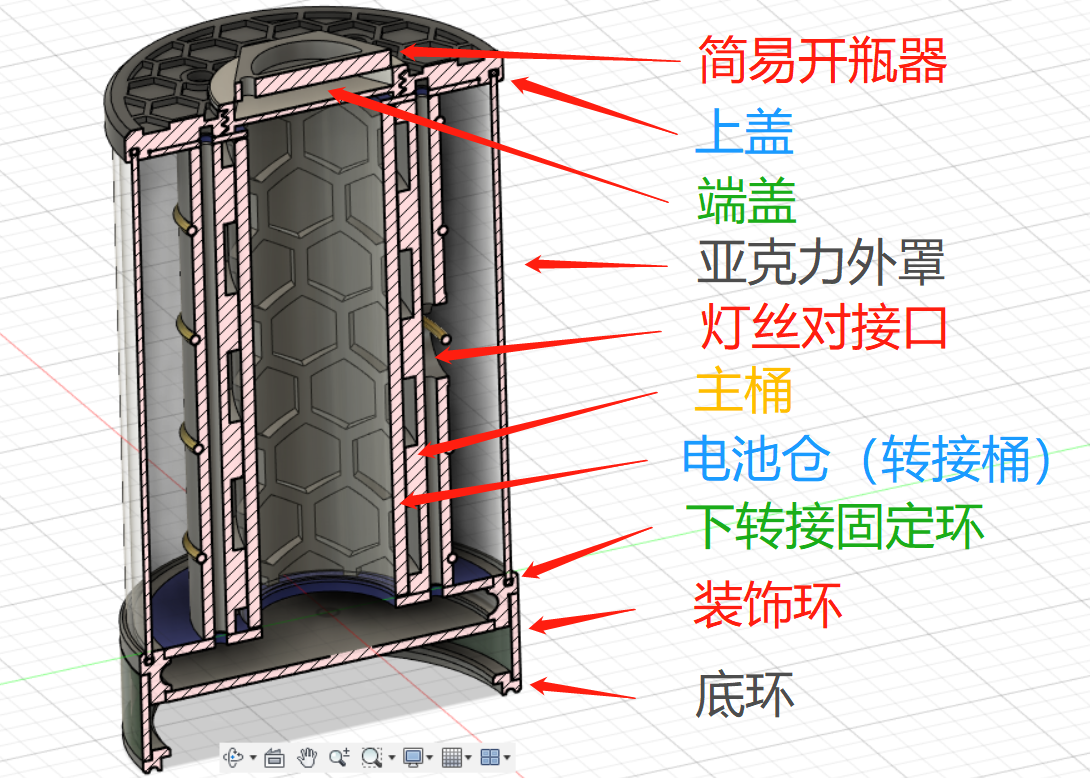
The above image is an overall description. The names of some parts and the STL file names do not match exactly. Just understand what it means. It is
also for reference during assembly. The structural
shell (lampshade) is made of acrylic tube cut from... Acrylic
cutting dimensions: outer diameter 60mm, wall thickness 2mm, length 83mm.
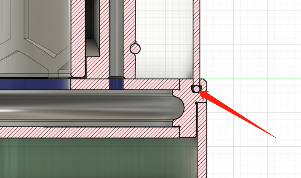
Both upper and lower adapter rings have sealing ring mounting slots to reduce wobbling caused by the acrylic outer cylinder cutting tolerances. The filament
docking area is used to connect the positive terminals of the upper and lower filaments. After docking, a cover plate/small badge or similar item can be used to cover this area.
For other 3D model issues, please refer to the modeling instructions or open the original design file (attached) to understand it yourself.

The internal battery adapter can be 3D printed using transparent material (which will be more expensive) or cut from acrylic columns (this will cause slight wobbling; if you have OCD, you can modify the main barrel model).
Acrylic cutting dimensions: acrylic tube with an outer diameter of 26mm and an inner diameter of 22mm. Cut an 80mm long section
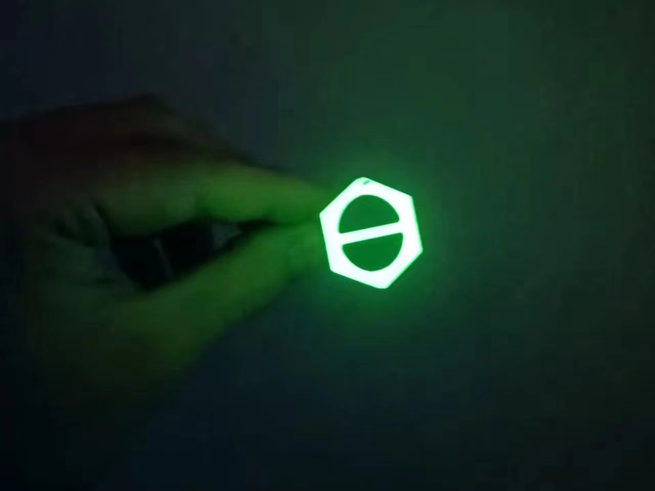
so that the honeycomb structure decorative ring on the inner wall can be seen through the adapter barrel. This

can be printed with luminescent material for a better effect.
The image above shows the effect of my printing using luminescent PLA (photographed after charging the luminescent material with a flashlight).

Bottle opener (used to open the battery compartment; files are in the attached compressed file).
It is recommended to use your own (or a friend's) FDM printer for the bottle opener; there is no need to use UV curing, as it is solid and very heavy (and expensive).
Mini bottle opener (luminescent version).
The mini bottle opener has a key ring design, which can be used as a pendant to hang on a keychain.
Other replica precautions:
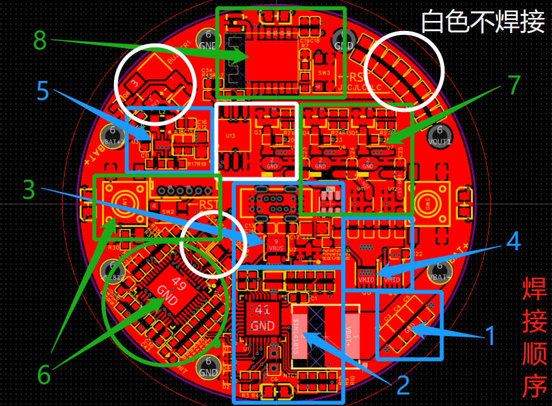
Please follow the numerical order in the image below to solder and debug the mainboard:
(As explained above, the image is provided for easy overall viewing).
I also used an external microcontroller for testing in the early stages. If there is a problem with the onboard microcontroller, you can use a flying wire to debug it.
The filament soldering center point soldering method is as follows: pre-tinning before soldering (silicone wire is recommended).

If 3D monkey printing is used for 3D parts and JLCPCB SMT soldering is used to attach the light board (economic SMT), the overall cost is approximately 200 yuan (calculated per unit, taking into account losses; the cost of assembling a single unit is relatively high, so multiple units can be shared).
For
any questions or suggestions regarding the project or the replication process, please join my discussion group!
Discussion group: 1016193632.
Welcome to follow my Bilibili account: @何电工.
Apologies:
This project was conceived at the end of 2022, and I signed up for the Spark Program in early 2023. Most of the hardware design verification work was completed in March, and the software and hardware integration was completed in April. However, due to frequent business trips and various personal reasons, the filming and video production work for the project has been delayed, which is why I haven't open-sourced this project. Now that 2023 is almost over, to avoid further delays, I've decided to open-source this project first.
On the other hand, the main design of this project took place about a year ago. During this year, I learned a lot of new hardware knowledge and also designed the "Multifunctional Test Pen" project. Looking back at "Fluorescent," I find many shortcomings, but I haven't had time to improve them.
Therefore, the current open-source version of this project is incomplete, including incomplete videos, imperfect open-source code, and certain software bugs. I apologize to all the electronics enthusiasts who are looking forward to this project, and to the organizers and supporters of the JLCIC Spark Program.

Regarding the video, I believe the actual presentation will be far better than the photos in the open-source code, so I will complete it and release it on Bilibili as soon as possible.
Acknowledgements:
Special thanks to the following friends and netizens for their help and contributions to this project in related fields:
Software: @ZeroDegreeHardware
; @HongKongRunFast; @NavelOrangeAppearance
: @HumanObservationDiary; @FlyingLittlePig; @SaintCrystalKiller; @EdisonImage
: @Mr.GengStudio; @Horizon__GouQiTea.
Thanks again to the friends who answered my questions and provided design assistance during the project design and debugging process!


 京公网安备 11010802033920号

 ML7022


