The project description
is divided into the following sections: Structural section: I purchased a used Changteng CTHT3-F4200 dual-motor 3-section height-adjustable desk frame from Xianyu (official specifications: noise level around 42 decibels, maximum load capacity 120KG, height adjustment range 600-1250mm).
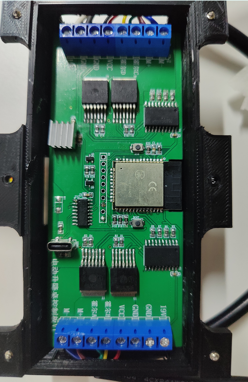
Main control section: I used the ESP32 as the main control chip for the following reasons:
1. Sufficient I/O ports (I need approximately 12, making the ESP32 suitable).
2. Sufficient interrupts (interrupts are crucial for monitoring motor Hall effect sensors, and each I/O port of the ESP32 can be used as an independent interrupt).
3. I2C pins are required (for OLED control).
4. Sufficiently large EEPROM is needed to store height information after power failure.
5. Wi-Fi functionality is required for future IoT planning.
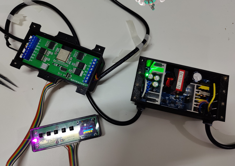
Motor control section: I used the BTS7960 motor driver chip (the 7970 also works). Its biggest feature is its ability to output a maximum current of 27V 43A. This is more than enough for driving the motor of the height-adjustable desk. It also requires a large heatsink to dissipate heat from the chip, which increases its size, but it's sufficient for the space under the desk.
Main power supply: After disassembling the motor, I found that each motor is an 18V, 4.3A worm motor. Testing revealed that the normal rotational current of the motor is around 2A. Considering the weight-bearing capacity, I chose a 15V 10A AD-DC power module. It costs approximately 15 yuan.
Display: A 0.96-inch OLED screen is used as the height display screen for showing the time, alarm settings, height, etc.
Fast charging: An IP5306 fast charging chip is used, with a maximum output power of 45W.
Open source
license:
This is a "Berkeley Software Distribution" license, a license that gives users a great deal of freedom; it can basically be considered as allowing "anything goes."
You are free to use and modify the source project, and you can also redistribute the modified project as open source or proprietary, but the following conditions must be met:
a) If the redistributed product includes the source project, the original BSD license must be included in the project;
b) If the redistributed product is only a binary library or software, the original BSD license must be included in the library or software's documentation and copyright notice;
c) You cannot use the name of the open source author or organization or the name of the original product for marketing purposes.
Project-related function
prompts:
Maximum height: 120CM, minimum height: 60CM;
Desktop area: 120cm x 60cm;
Maximum load capacity: 50KG, and the height cannot be rebounded;
Number of motors: 1-2;
Screen display: time, current table height;
USB fast charging, fast charging protocol is not limited;
Power failure memory, ensuring that the table height remains consistent after a power failure and restart;
Noise level during table raising and lowering: below 45dB;
Alarm clock reminder supported;
Project attributes :
This project is being publicly disclosed for the first time and is an original project by the author. The project has not won any awards in other competitions.
Project Schedule
: July 1st: The height-adjustable desk arrived and was tested. The size and installation location of each module were determined, and modeling of the control board casing began.
July 3rd: The control board was manually soldered, code was written, and the performance of the height-adjustable desk was tested to ensure it met requirements.
July 10th: PCB schematic design was completed, including (motor drive, control section, OLED screen display, button control, limit switch settings, USB fast charging settings). Power-off memory and alarm clock were placed in the final testing section.
July 13th: PCB design and prototyping.
July 13th: Electronic component procurement
. July 20th: PCB soldering and testing.
Note: I am concerned about time conflicts and insufficient testing time. I will consider that the power module may need to be done later. Please understand.
Design Principles:
First, the hardware was measured and chips were selected to determine the appropriate PCB size and chip type to ensure that the design requirements are met.
By disassembling the motors, each motor has two Hall effect sensors. When the motor's magnetic ring rotates, the two Hall effect sensors detect different values due to the S and N poles of the magnetic ring. For example, if Hall effect sensor 1 detects a low level and Hall effect sensor 2 detects a high level, it indicates that the motor is rotating clockwise, and the table is rising. If Hall effect sensor 1 detects a high level and Hall effect sensor 2 detects a low level, it indicates that the motor is rotating counterclockwise, and the table is falling. Therefore, I set up five buttons: up, down, alarm hour timer setting, alarm minute timer setting, and clear button.
When the "raise" button is pressed, the ESP32 outputs two PWM control signals to raise the two table legs. Simultaneously, the motor rotation triggers a Hall sensor, which detects the rotation, initiating an interrupt and sending the read pulses to the ESP32 for recording. When the desired height is reached, the current height is calculated using a function formula, displayed on the OLED screen, and saved to the EEPROM to prevent data loss in case of power failure. Through repeated calculations and measurements, it was found that the table outputs 2569 pulses at its maximum height of 1200mm, meaning the motors stop rising when the height reaches 1200mm.
When the "lower" button is pressed, the ESP32 outputs two PWM signals to lower the two table legs. When the detected height is greater than or equal to 0, it indicates the bottom has been reached, and the descent stops. Similarly, when the lowest height is reached, the pulse count is 0.
For network time and alarm clock: After the table is powered on, the ESP32 automatically connects to the home Wi-Fi network and obtains the network time, displaying it on the OLED screen. Users can set the desired alarm time by pressing the corresponding alarm timer button. The set time will be displayed on the OLED screen. The network time is read and compared with the set time; if they are equal, a buzzer is activated.
EEPROM Section: When the up or down button is pressed, the current height is stored in the EEPROM. After a power outage, the height is saved in the EEPROM. When power is restored, the previously saved height is read directly, and the up or down height calculation is performed at that height to prevent the current height value from being cleared to zero after a power outage.
Power supply section: Measurements were taken using a Zhengdian Atom adjustable power supply. It was found that under normal operating conditions (adjustable power supply set to 12V 5A), the current of a single motor is about 2.5A. Since the motor parameters are 18V 4.3A, considering the load-bearing capacity and starting current, an AC-DC 15V 10A power supply module was selected for this test.
The software description
will provide a detailed analysis of the program. If you don't understand, you can watch the video (Bilibili: Zhao Gongzi's PCB).
The library functions used in this project are
: #include
#include
#include
#include
#include
#include
#include
#include
#include
The pin definitions for ESP32 are:
const int ENC_A = 22; // Hall sensor A
const int ENC_B = 23; // Hall sensor B
const int ENC_C = 34;
const int ENC_D = 35;
const int RPWM = 18; // RPWM pin
const int LPWM = 19; // LPWM pin
const int RPWM1 = 33;
const int LPWM1 = 32;
const int BuzzerPin = 21; // Buzzer
const int Button1 = 17; // Up button
const int Button2 = 16; // Down button
const int Button3 = 25; // Hour button
const int Button4 = 26; // Minute button
const int Button5 = 27; // Cancel button
Next is the Wi-Fi part:
#define WIFI_SSID "OnePlus 9 Pro"
#define WIFI_PASSWORD "12345678"
WiFiUDP ntpUDP;
NTPClient timeClient(ntpUDP, "pool.ntp.org");
// The time of the current area can be accurately obtained through "pool.ntp.org" and displayed on the OLED.
Main variables:
int alarmHour = 0; // Alarm hour
int alarmMinute = 0; // Alarm minute
bool alarmOn = false; // Alarm status
volatile int contador = 0; // Number of pulses output by Hall 1
volatile bool direction = false; // false for rising, true for falling
volatile int contador1 = 0; // Number of pulses output by Hall 2
volatile bool direction1 = false; // false for rising, true for falling
const int MIN_HEIGHT = 0; // Minimum height
const int MAX_HEIGHT = 60; // Maximum height
const int MAX_PULSES = 2569; // Maximum encoder pulse value
int currentHeight = 0; // Current height
int currentHeight1 = 0;
bool alarmEnabled = false; // Alarm enabled
bool Button1State = HIGH; // Button state
bool Button2State = HIGH;
bool Button3State = HIGH;
bool Button4State = HIGH;
bool Button5State = HIGH;
A rather poor table pattern:
static const uint8_t image_data_Saraarray[1024] = { // Animation OLGO
0x00,0x00,0x06,0x00,0x00,0x00,0x00,0x00,0x00,0x00,0x1F,0x80,0x00,0x00,0x00,0x00,
0x00,0x00,0x7F,0xC0,0x00,0x00,0x00,0x00,0x00,0x00,0xFF,0xF0,0x00,0x00,0x00,0x00,
0x00,0x03,0xFF,0xFC,0x00,0x00,0x00,0x00,0x00,0x0F,0xFF,0xFE,0x00,0x00,0x00,0x00,
0x00,0x3F,0xFF,0xFF,0x80,0x00,0x00,0x00,0x00,0x7F,0xFF,0xFF,0xE0,0x00,0x00,0x00,
0x01,0xFF,0xFF,0xFF,0xF8,0x00,0x00,0x00,0x07,0xFF,0xFF,0xFF,0xFE,0x00,0x00,0x00,
0x1F,0xFF,0xFF,0xFF,0xFF,0x00,0x00,0x00,0x3F,0xFF,0xFF,0xFF,0xFF,0xC0,0x00,0x00,
0x7F,0xFF,0xFF,0xFF,0xFF,0xF0,0x00,0x00,0x7F,0xFF,0xFF,0xFF,0xFF,0xF8,0x00,0x00,
0x0F,0xFF,0xFF,0xFF,0xFF,0xFE,0x00,0x00,0x03,0xFF,0xFF,0xFF,0xFF,0xFF,0x80,0x00,
0x00,0xFF,0xFF,0xFF,0xFF,0xFF,0xE0,0x00,0x00,0x7F,0xFF,0xFF,0xFF,0xFF,0xF0,0x00,
0x00,0x1F,0xFF,0xFF,0xFF,0xFF,0xFC,0x00,0x00,0x07,0xFF,0xFF,0xFF,0xFF,0xFF,0x00,
0x00,0x03,0xFF,0xFF,0xFF,0xFF,0xFF,0xC0,0x00,0x00,0xFF,0xFF,0xFF,0xFF,0xFF,0xE0,
0x00,0x00,0x3F,0xFF,0xFF,0xFF,0xFF,0xF8,0x00,0x00,0x4F,0xFF,0xFF,0xFF,0xFF,0xFE,
0x00,0x00,0x63,0xFF,0xFF,0xFF,0xFF,0xFF,0x00,0x00,0x6C,0xFF,0xFF,0xFF,0xFF,0xFF,
0x00,0x00,0x66,0x7F,0xFF,0xFF,0xFF,0xF8,0x00,0x00,0x67,0x3F,0xFF,0xFF,0xFF,0xF0,
0x00,0x00,0x67,0x0F,0xFF,0xFF,0xFF,0x80,0x00,0x00,0x67,0x03,0xFF,0xFF,0xFF,0x00,
0x00,0x00,0x67,0x01,0xFF,0xFF,0xFC,0x00,0x00,0x00,0x67,0x00,0x3F,0xFF,0xF0,0x00,
0x00,0x00,0x67,0x00,0x1F,0xFF,0xE0,0x00,0x00,0x00,0x67,0x00,0x07,0xFF,0x80,0x00,
0x00,0x00,0x67,0x00,0x01,0xFC,0x00,0x00,0x00,0x00,0x67,0x00,0x00,0x79,0x00,0x00,
0x00,0x00,0x67,0x78,0x00,0x57,0x00,0x00,0x00,0x00,0x67,0xFE,0x00,0x67,0x00,0x00,
0x00,0x00,0x67,0xFE,0x00,0x77,0x00,0x00,0x00,0x00,0x67,0xF0,0x00,0x77,0x00,0x00,
0x00,0x00,0x67,0xE0,0x00,0x77,0x00,0x00,0x00,0x00,0xE7,0xC0,0x00,0x77,0x00,0x00,
0x00,0x01,0xE7,0x00,0x00,0x77,0x00,0x00,0x00,0x07,0xEC,0x00,0x00,0x77,0x00,0x00,
0x00,0x1F,0xF8,0x00,0x00,0x77,0x00,0x00,0x00,0x3F,0xE0,0x00,0x00,0x77,0x00,0x00,
0x00,0x7F,0x00,0x00,0x00,0x77,0x00,0x00,0x00,0x0E,0x00,0x00,0x00,0x77,0x00,0x00,
0x00,0x04,0x00,0x00,0x00,0x77,0x00,0x00,0x00,0x04,0x00,0x00,0x00,0x77,0x00,0x00,
0x00,0x00,0x00,0x00,0x00,0x77,0x38,0x00,0x00,0x00,0x00,0x00,0x00,0x77,0xFE,0x00,
0x00,0x00,0x00,0x00,0x00,0x77,0xFE,0x00,0x00,0x00,0x00,0x00,0x00,0x77,0xF8,0x00,
0x00,0x00,0x00,0x00,0x00,0x77,0xF0,0x00,0x00,0x00,0x00,0x00,0x00,0x77,0xC0,0x00,
0x00,0x00,0x00,0x00,0x00,0xF7,0x80,0x00,0x00,0x00,0x00,0x00,0x03,0xF6,0x00,0x00,
0x00,0x00,0x00,0x00,0x0F,0xF8,0x00,0x00,0x00,0x00,0x00,0x00,0x3F,0xF0,0x00,0x00,
0x00,0x00,0x00,0x00,0x3F,0xC0,0x00,0x00,0x00,0x00,0x00,0x00,0x0E,0x00,0x00,0x00,
0x00,0x00,0x00,0x00,0x00,0x00,0x00,0x00,0x00,0x00,0x00,0x00,0x00,0x00,0x00,0x00,0x00,0x00,
};
Next is the setup() function:
Initialize serial port: Serial.begin(115200); // Initialize serial port
Initialize EEPROM: EEPROM.begin(EEPROM_SIZE);
Initialize OLED: Wire.begin(OLED_SDA, OLED_SCL);
IO pin initialization:
pinMode(ENC_A, INPUT); // Hall pin initialization
pinMode(ENC_B, INPUT);
pinMode(ENC_C, INPUT);
pinMode(ENC_D, INPUT);
pinMode(RPWM, OUTPUT); // Motor drive part initialization
pinMode(LPWM, OUTPUT);
pinMode(RPWM1, OUTPUT);
pinMode(LPWM1, OUTPUT);
pinMode(BuzzerPin, OUTPUT);
pinMode(Button1, INPUT_PULLUP); //Button 1 is in pull-up input mode
pinMode(Button2, INPUT_PULLUP); //Button 2 is in pull-up input mode
pinMode(Button3, INPUT_PULLUP);
pinMode(Button4, INPUT_PULLUP);
pinMode(Button5, INPUT_PULLUP);
Set interrupt detection Hall pulse:
attachInterrupt(digitalPinToInterrupt(ENC_A), interruption, RISING); //Rising edge triggered
attachInterrupt(digitalPinToInterrupt(ENC_B), interruption, RISING);
attachInterrupt(digitalPinToInterrupt(ENC_C), interruption1, RISING); //Rising edge triggered
attachInterrupt(digitalPinToInterrupt(ENC_D), interruption1, RISING);
This function determines whether the current state is rising or falling:
void interruption(){
int stateA = digitalRead(ENC_A);
int stateB = digitalRead(ENC_B);
if(stateA == HIGH && stateB == LOW){
contador++;
if(contador > MAX_PULSES){
contador = MAX_PULSES;
}
direction = true;//
}else if(stateA == LOW && stateB == HIGH){
contador--;
if(contador
contador = 0;
}
direction = false;
}
currentHeight = map(contador, 0 , MAX_PULSES, MIN_HEIGHT, MAX_HEIGHT);
}
Note: interruption1 similarly
reads the value saved by the EEPROM when the power is off and assigns it to the current height
currentHeight = EEPROM.read(0);
currentHeight1 = EEPROM.read(1);
currentHeight = constrain(currentHeight, MIN_HEIGHT, MAX_HEIGHT);
currentHeight1 = constrain(currentHeight1, MIN_HEIGHT, MAX_HEIGHT);
updatwMotorPosition(); //When the power is off, the height is 30cm. Therefore, the initial value should be 30cm after power is restored.
void updatwMotorPosition() {
int pulses = map(currentHeight, MIN_HEIGHT, MAX_HEIGHT, 0, MAX_PULSES);
contador = pulses;
int pulses1 = map(currentHeight1, MIN_HEIGHT, MAX_HEIGHT, 0, MAX_PULSES);
contador1 = pulses1;
}
Next is the IOOP function:
//OLED displays the current time
display.clearDisplay(); //Clear the display image
display.setTextSize(1);
display.setTextColor(WHITE);
display.setCursor(20, 13);
display.print("T:");
display.println(timeClient.getFormattedTime()); // //
OLED displays the timer
display.setCursor(20, 30);
display.print("DING:"); //"DING --fixed"
display.print(alarmHour); // Hours
display.print(":");
display.println(alarmMinute); // Minutes
checkAlarmTrigger(); // Start the timer function
// Compare the current time with the set time, and trigger the buzzer if they are equal
void checkAlarmTrigger(){
int currentHour = timeClient.getHours();
int currentMinute = timeClient.getMinutes();
if (alarmEnabled && currentHour == alarmHour && currentMinute == alarmMinute) {
digitalWrite(BuzzerPin, HIGH);
Serial.println("Buzzer alarm");
Serial.print("currentHour: ");
Serial.println(currentHour);
Serial.print("currentMinute: ");
Serial.println(currentMinute);
Serial.print("alarmHour: ");
Serial.println(alarmHour);
Serial.print("alarmMinute: ");
Serial.println(alarmMinute);
Serial.print("alarmEnabled: ");
Serial.println(alarmEnabled);
// You can add code here to display the alarm information on the OLED
delay(500);
cancelAlarm(); // Automatically cancel after the alarm rings
}
}
Next is the button reading part
Button1State = digitalRead(Button1); // Read the state of button 1
Button2State = digitalRead(Button2); // Read the state of button 2
Button3State = digitalRead(Button3);
Button4State = digitalRead(Button4);
Button5State = digitalRead(Button5);
if(Button1State == LOW &&
if (!direction) { ShangSheng
();
if (currentHeight >= MAX_HEIGHT) {
ShangShengStup();
}
}
EEPROM.write(0, currentHeight);
EEPROM.write(1, currentHeight1);
EEPROM.commit();
} else {
ShangShengStup();
}
if (Button2State == LOW && currentHeight1 > MIN_HEIGHT) { // If button 2 is pressed, the table leg starts to descend
if (direction) {
XiaJiang();
if (currentHeight
XiaJiangStup();
}
}
EEPROM.write(0, currentHeight);
EEPROM.write(1, currentHeight1);
EEPROM.commit();
} else {
XiaJiangStup();
}
if (Button3State == LOW) { // Set alarm hour
delay(200);
incrementAlarmHour();
}
if (Button4State == LOW) { // Set alarm minute
increment(200);
incrementAlarmMinute();
}
if(Button5State == LOW){// Clear alarm
increment(200);
cancelAlarm();
}
Motor rotation and stop functions:
void ShangSheng(){
digitalWrite(LPWM, LOW);
analogWrite(RPWM, 200);
digitalWrite(RPWM1, LOW);
analogWrite(LPWM1, 200);
}
void ShangShengStup(){
digitalWrite(LPWM, LOW);
analogWrite(RPWM, 0);
digitalWrite(RPWM1, LOW);
analogWrite(LPWM1, 0);
}
void XiaJiang(){
digitalWrite(RPWM, LOW);// Rotate clockwise;
analogWrite(LPWM, 200);
digitalWrite(LPWM1, LOW);
analogWrite(RPWM1, 200);
}
void XiaJiangStup(){
digitalWrite(RPWM, LOW);
analogWrite(LPWM, 0);
digitalWrite(LPWM1, LOW);
analogWrite(RPWM1, 0);
}
Alarm clock function:
void triggerBuzzer(){// Trigger the alarm
digitalWrite(BuzzerPin, HIGH);
delay(1000);
digitalWrite(BuzzerPin, LOW);
delay(1000);
}
void incrementAlarmHour() {// Set the hour
alarmHour++;
alarmEnabled = true;
if (alarmHour > 23) {
alarmHour = 0;
}
}
void incrementAlarmMinute() {// Set the minute
alarmMinute++;
alarmEnabled = true;
if (alarmMinute > 59) {
alarmMinute = 0;
}
}
void cancelAlarm() {// Code to stop the buzzer
alarmEnabled = false;
alarmHour = 0; // Clear the alarm hour
alarmMinute = 0; // Clear the alarm minute
// The code to stop the buzzer
is `digitalWrite(BuzzerPin, LOW);
`.
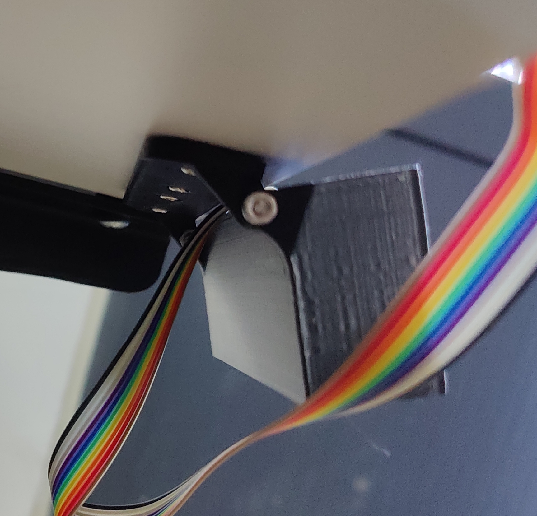
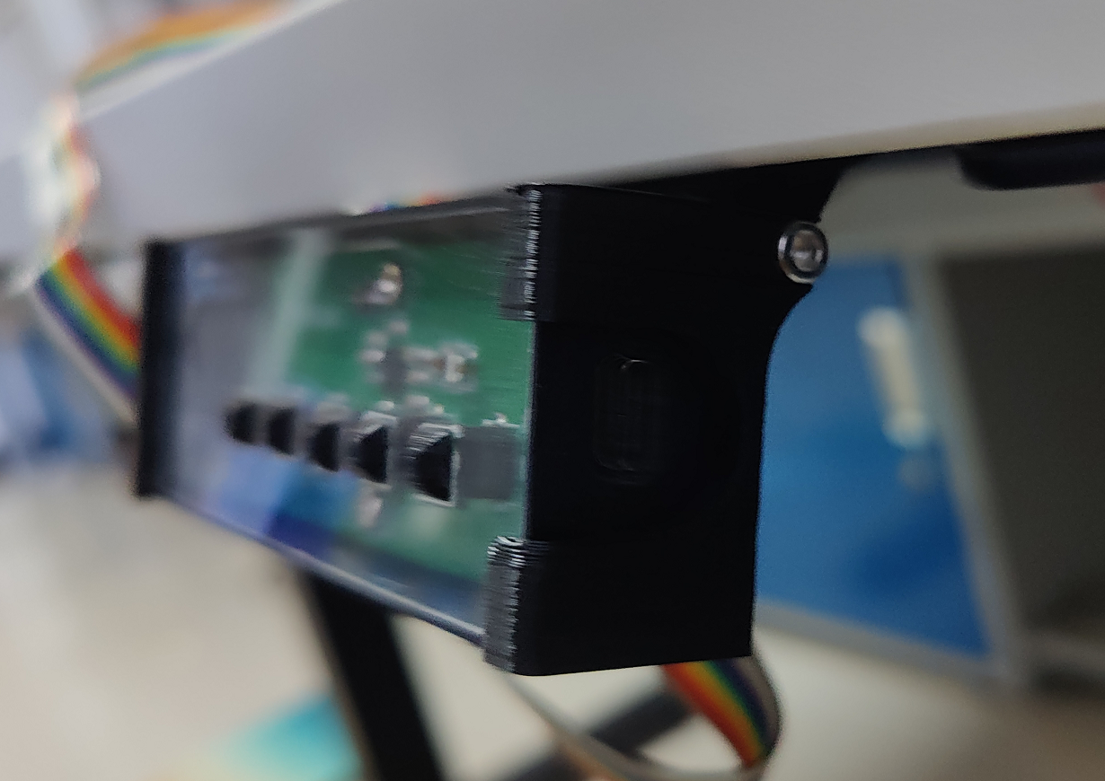
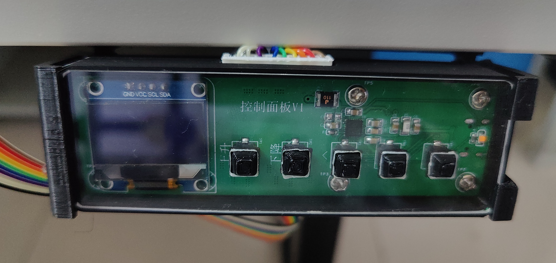
Physical
demonstration: Images of the actual product are provided, with descriptions added.
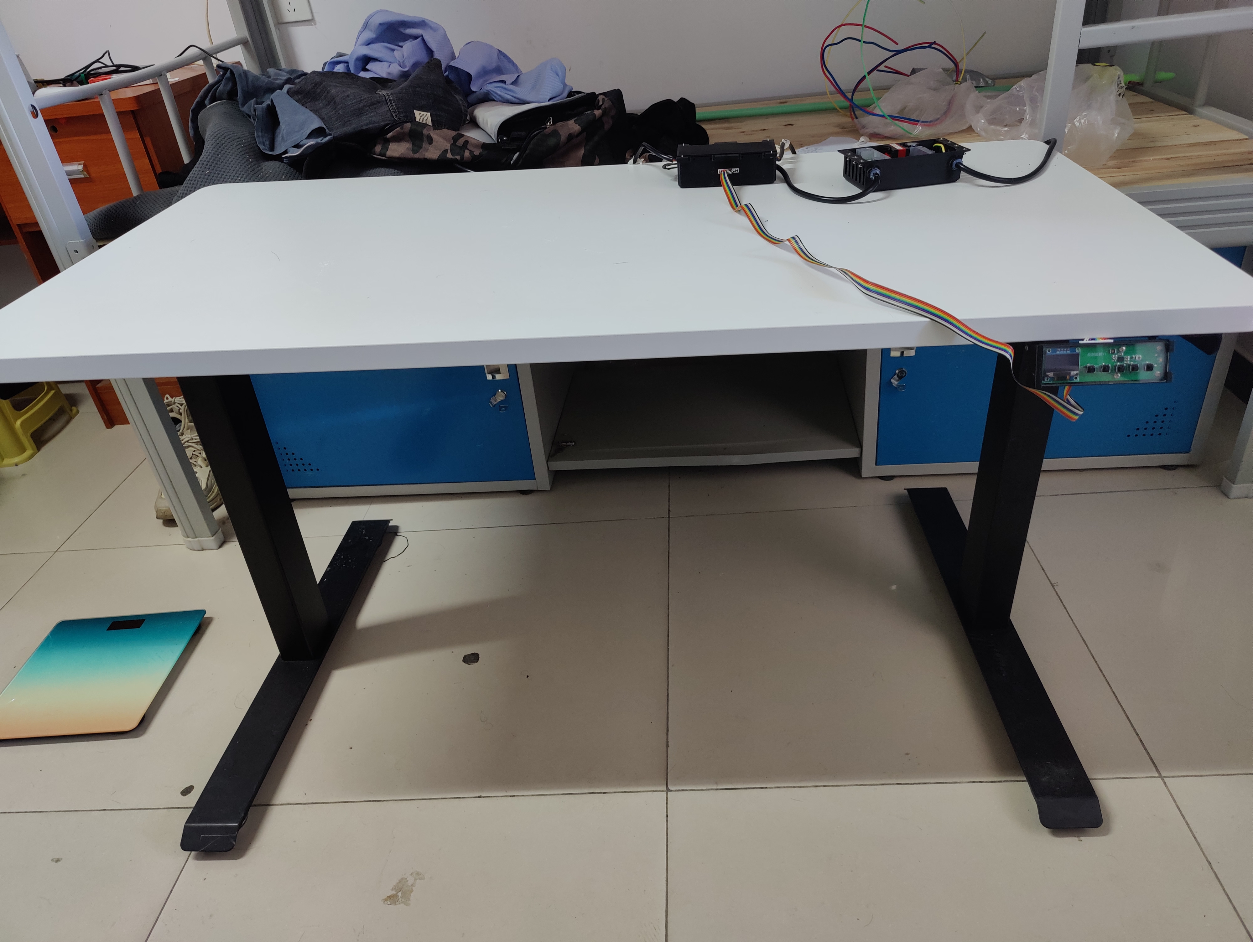

The control panel has a detachable and foldable design .
Design
notes: This section outlines some precautions to take during the production process (optional).
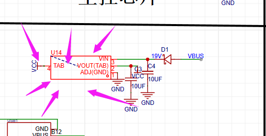
The AMS1117 used in the circuit diagram is currently considered to cause significant heat generation; the AMS117 I purchased appears to be defective. Replacing it with an AS1117 is recommended.
When actually programming, a program to clear the ESP32 and EEPROM needs to be programmed first to prevent incorrect read heights.

The capacitors marked with arrows in the fast charging circuit can be modified as needed.
Other
Bilibili (Bilibili.com) listings: Spark Project - Electric Height-Adjustable Desk Hardware Part;
Electric Height-Adjustable Desk Programming.
Demo Videos: Upload the demo video as an attachment. Attachments are limited to a maximum file size of 50MB. Files larger than 50MB can be hosted on other cloud storage services or video websites; simply include the link here.
Project Attachments: Entries participating in the event must upload the relevant program attachments to an open-source platform or personal code storage cloud. Attachments are limited to a maximum size of 50MB (please do not upload to the LCSC workspace, as there are restrictions).


 京公网安备 11010802033920号

 NE570
NE570


