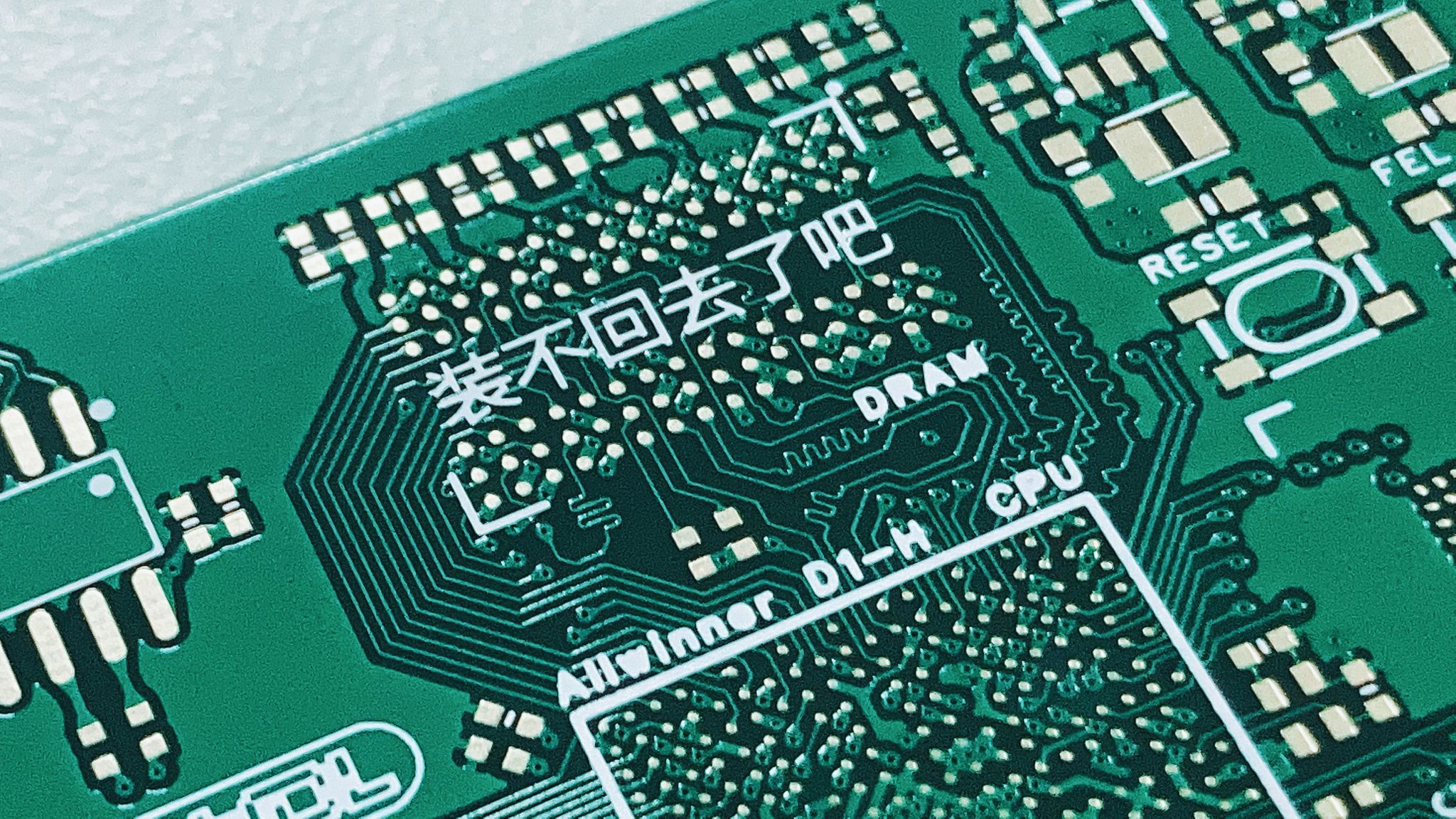
This is a full-screen Linux mini-program based on the Allwinner D1-H chip, supporting up to 2GB of RAM and 256GB of storage. It features a RISC-V 64 instruction set, onboard UART and OTG, a 3.2-inch 800x320 screen, 2.4G Wi-Fi for internet browsing, and Bluetooth. It was submitted to the "Hard Technology · Chip Species 'Xuan Tie Cup' RISC-V Application Innovation Competition" 2022 Spring Season (April 18 - September 15). Features include: RISC-V 64 instruction set, full-screen Linux mini-program, onboard UART and OTG, a 3.2-inch screen, 2.4G Wi-Fi support, Bluetooth 4.1, onboard HDMI for maximum 4K output, DDR3 1866e MMC 5.0.
PDF_YuzukiRuler Pro Portable Linux Ruler.zip
Altium_YuzukiRuler Pro Portable Linux Ruler.zip
PADS_YuzukiRuler Pro Portable Linux Ruler.zip
BOM_YuzukiRuler Pro Portable Linux Ruler.xlsx
90746
Yuzuki HCC HDMI Capture Card
A low-cost HDMI capture card based on the MS2109, costing only 23 yuan, supports up to 3840x2160@30 input, and features a Type-C interface.
A low-cost HDMI capture card based on the MS2109, costing only 23 RMB. Features
a Type-C USB 2.0 interface,
full-height HDMI
compatibility, DVI 1.0
support, HDCP 1.4 support (the firmware does not provide an HDCP key; please apply for one yourself),
YUV & JPEG output
compatibility, UVC 1.0
support, audio capture
, and video capture.
Maximum video input resolution is 3840x2160@30,
and maximum output resolution is 1920*1080@30.
(Image attached:

After firmware flashing, two devices will be displayed, one audio input and one video input.

Supported USB output resolutions are listed
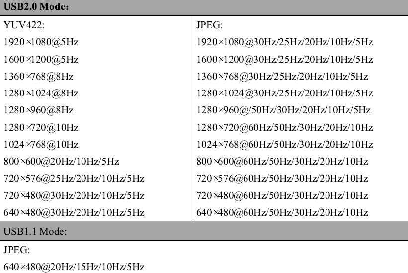
.) Firmware flashing method:
Use an EEPROM programmer to flash the firmware into the EEPROM before soldering
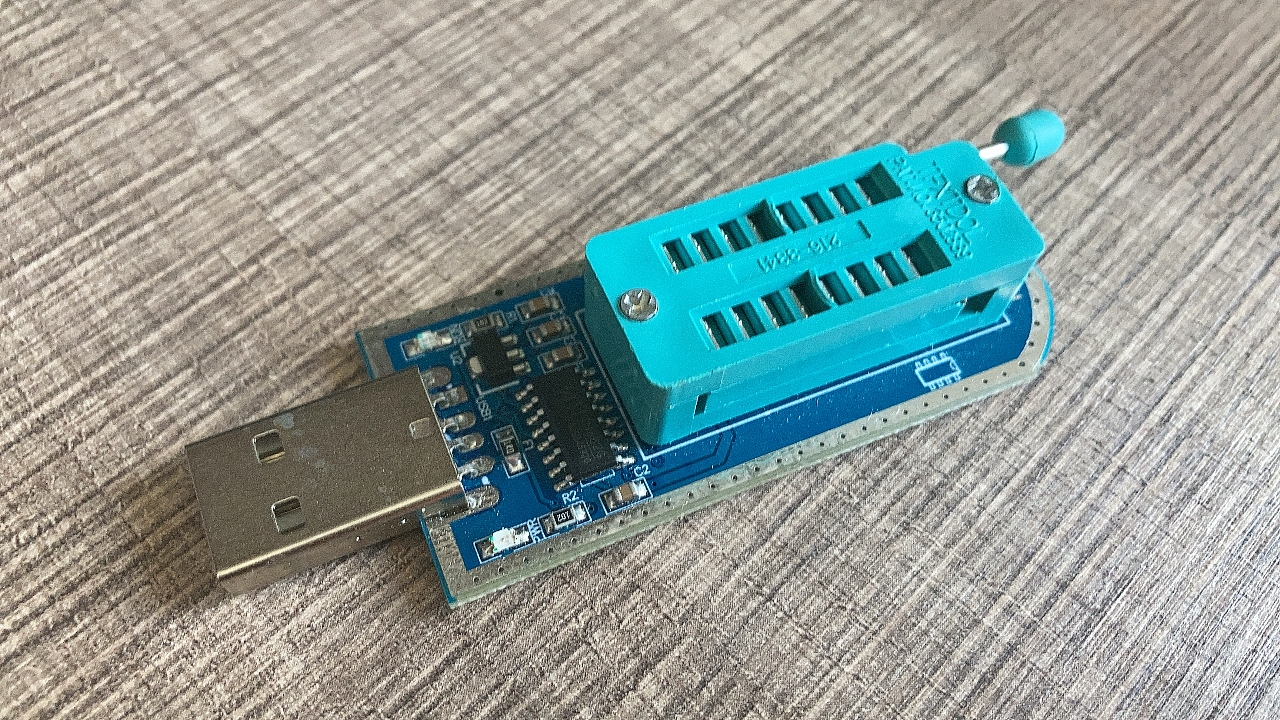
other components .
YuzukiHD open-source hardware and software exchange group: 685554363
YuzukiHCC_Firmware.bin
PDF_Yuzuki HCC HDMI Capture Card.zip
Altium_Yuzuki HCC HDMI Capture Card.zip
PADS_Yuzuki HCC HDMI Capture Card.zip
BOM_Yuzuki HCC HDMI Capture Card.xlsx
90747
#9th LCSC Electronics Contest# Klipper 3D Printed Air Circulation System
This project includes a control system for the air circulation system of the Voron 0.2 3D printer. To achieve air circulation, temperature measurement, RGB lighting, and other functions, the project incorporates several improvements specifically for the Voron 0. Support for more 3D printers will be added later as needed.
Project Video Introduction
[Open Source] Voron0 Air Circulation System_Bilibili_bilibili
Project Function Introduction
This project is a control system for air circulation in Voron 0.2 3D printing. To achieve air circulation, temperature measurement, RGB lighting, and other functions, the project includes several improvements specifically for Voron0. More 3D printer support will be added later based on demand.
Project Attributes This
is an original, first-time public work. It has not participated in any other activities, has not won any awards in other competitions, and has not participated in any school defenses.
Open Source License
CERN Open Hardware
License
Hardware Part
PCB Board
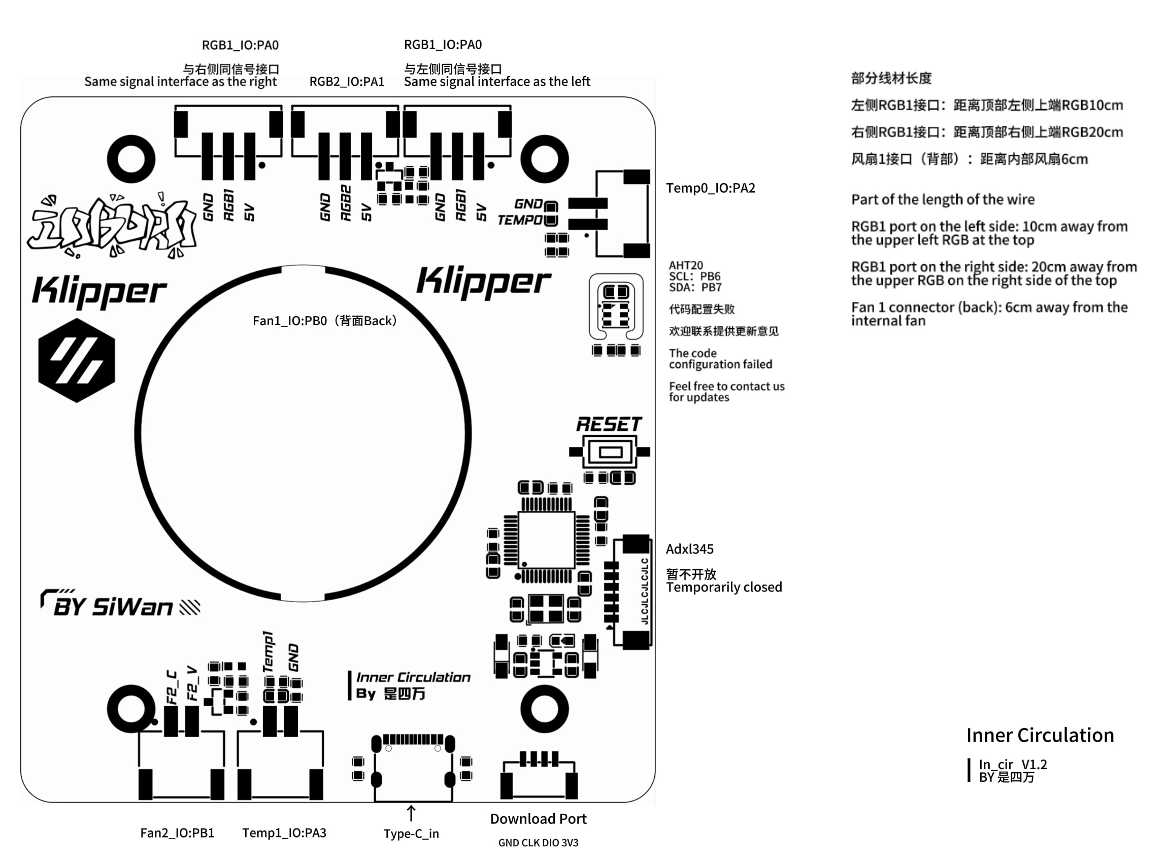
1. The MCU uses STM32F103, with the main controller being STM32F103C8T6CBT6, F103C6T6C6T6A, or F031C6T6.
2. The power supply uses an LDO + Type-C input scheme; the main power supply USB directly supplies the fan; the USB voltage is stepped down to 3.3V by the LDO for powering the STM32, etc.
3. Temperature and humidity sensor usage.
4. USB connection is used. The download circuit uses an interface for downloading. Currently, STLink is used for code downloading (I frequently use it for development).
The F103 does not support HID by default, making downloading cumbersome. I'm using STLink instead of serial port downloading due to cost constraints.
This may be modified later, but for now, it will be as is.
5. The number of LED indicators has been increased to 3:
Fan (blue) status indicator, two onboard, used to display the current fan status;
Power (red) indicator lights up when powered on, indicating normal power supply.
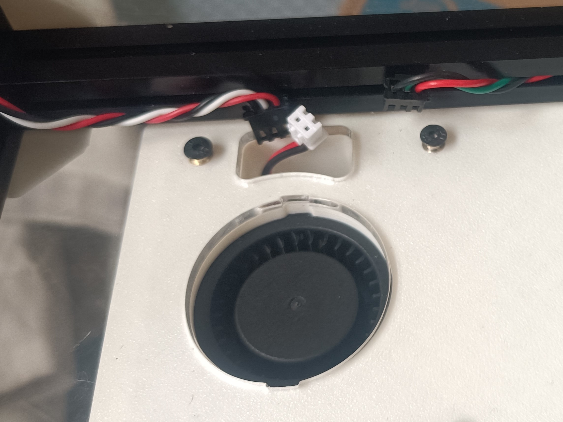
6. The fan is controlled using a 3400 MOSFET, which is a common solution
. Fan specifications: 5015 fan, recommended 5V for the core circuit board (this project has a corresponding circuit board; if you do not choose to use it, you can choose a suitable fan voltage).
Note: Additional projects can be adapted to fans with different voltages (opening time to be determined).
Installation related
3D model release link: https://makerworld.com.cn/zh/models/567846#profileId-497846
Hot melt nut specifications: M3*4*4, quantity 12 (height can be increased, outer diameter must be 4mm).

Screw specifications: M3*8-12 Quantity 12 (8-12mm height is acceptable; some screws may melt due to temperature, causing inconsistent insertion heights; a relatively long nut can be selected).

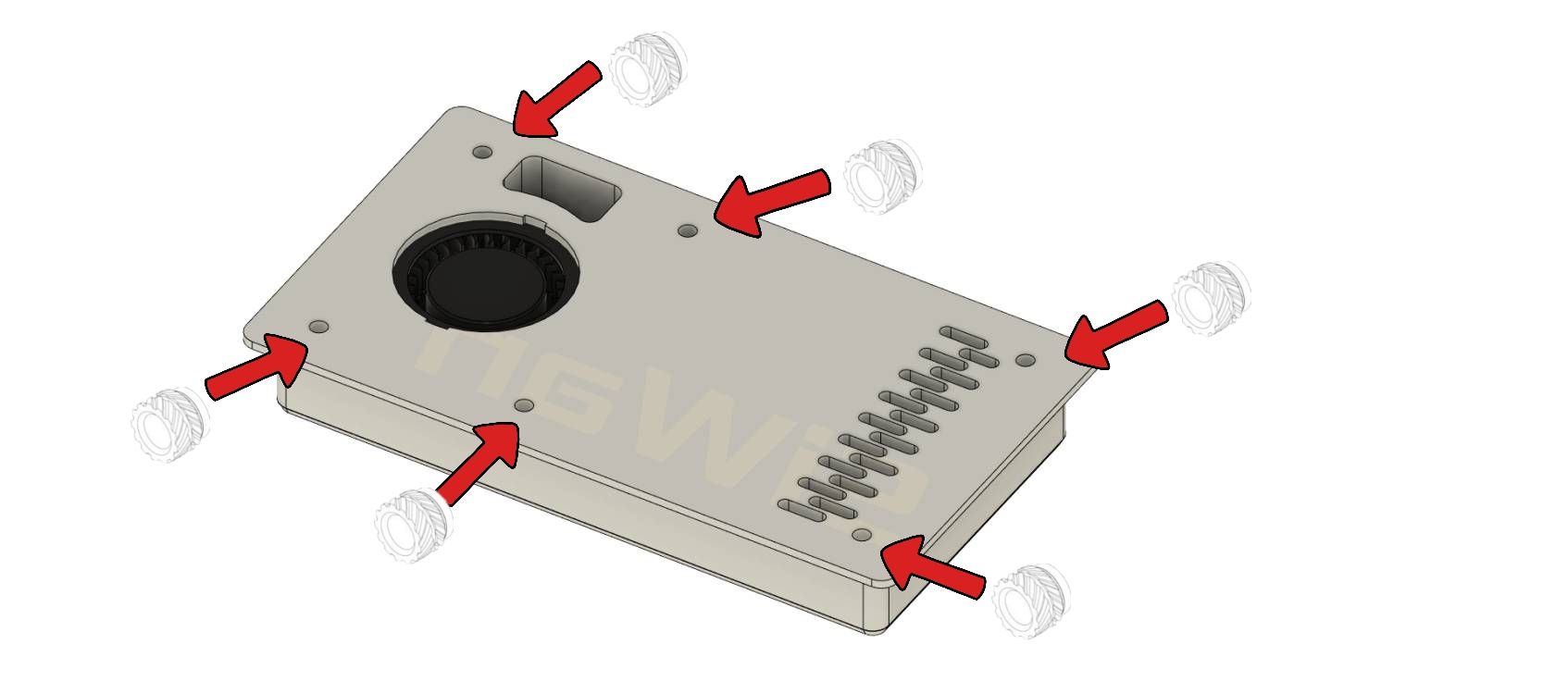
Please don't forget there are 6 screws on the back. I haven't drawn an installation diagram.
Pinout analysis.
Klipper software code
[include CabinMcu.cfg]
# File code that needs to be referenced in printer.cfg.
Control board configuration code
#CabinMcu.cfg
[mcu CabinMcu]
serial: /dev/serial/by-id/usb-Klipper_stm32f103xe_36FF69063041423815251743-if00
# [temperature_sensor flypilite2]
# sensor_type: temperature_host
# [temperature_sensor mcu1]
# sensor_type: temperature_mcu
# [adxl345]
# cs_pin:CabinMcu:PA4 # Defines the pin corresponding to CS for the MCU, connected to CS
# spi_bus:spi1
# [resonance_tester]
# accel_chip: adxl345
# min_freq: 5 # Minimum frequency for resonance test
# max_freq: 133.33 # Maximum frequency for resonance test
# accel_per_hz: 75 # Acceleration per Hertz (mm/sec), acceleration = acceleration per Hertz * frequency. If the resonance is too strong, this value can be reduced. Default 75
# hz_per_sec: 1 # Test speed. Smaller values will increase test time, while larger values will reduce test accuracy (Hz/sec == sec^-2), default 1
# probe_points: #
60, 60, 20 # an example
######################################## Temp# ...
sensor_pin:CabinMcu:PA3# min_temp: -10# max_temp: 120
########################################## FANs# ...
# Define the lower fan circulation interface # [fan_generic Fan2] # pin:CabinMcu: PB1 # Signal interface kick_start_time: 0.5 # Startup time (do not change) off_below: 0.10 # Do not change
########################################## RGB######################################## Define the left and right RGB interfaces, sharing the same pin but with two interfaces [neopixel Cabin_RGB1] pin:CabinMcu: PA0chain_count:6 # Number of LEDs color_order: GRB # Color order initial_RED: 0 # Red LED default value at power-on, maximum is 1 initial_GREEN: 0 # Green LED default value at power-on, maximum is 1 initial_BLUE: 0# The default value for the blue LED is 1.
#Define the middle RGB interface# [neopixel RGB2]# pin:CabinMcu:PA1# chain_count: 8# color_order: GRB
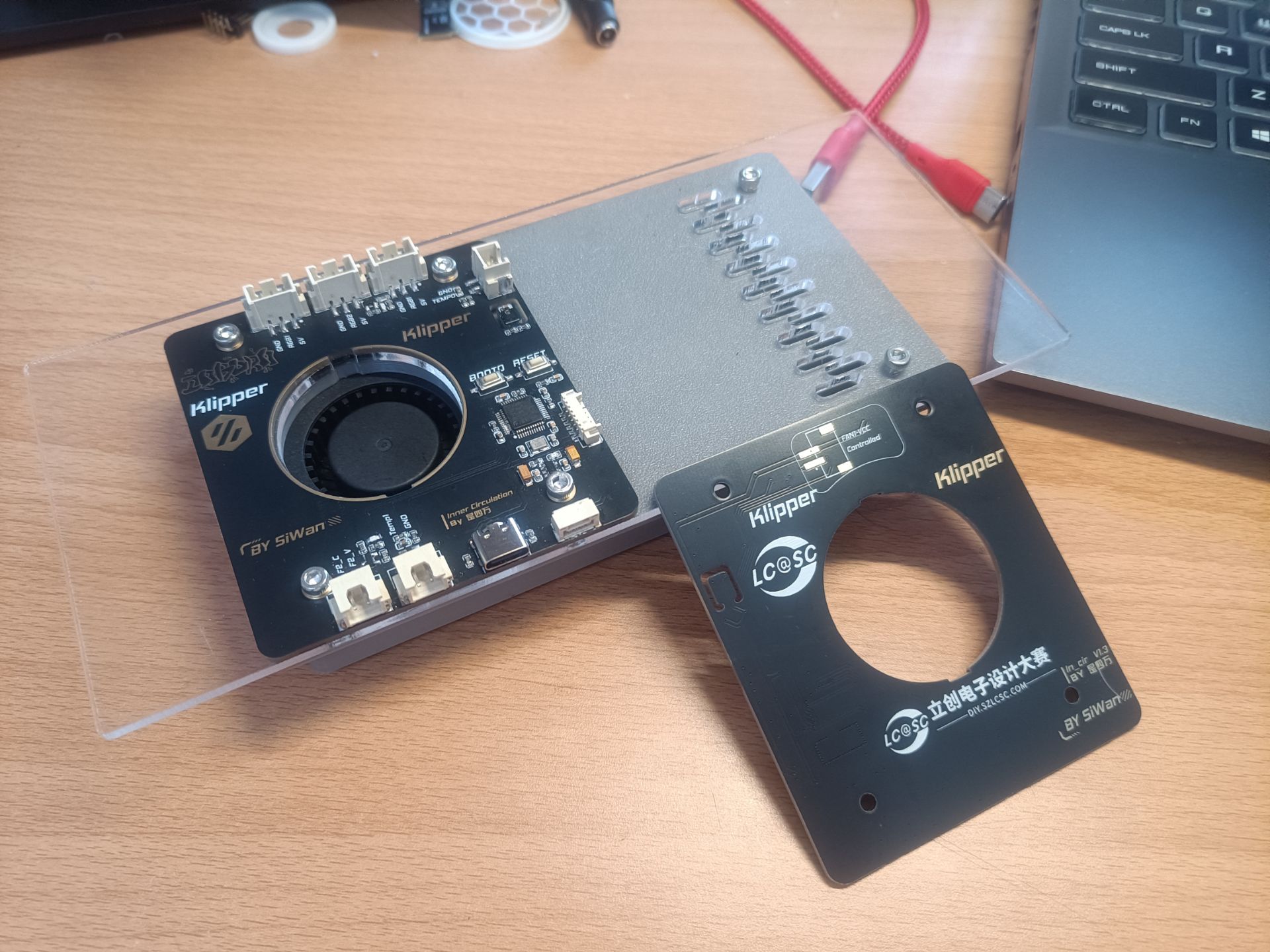
Actual product images:

Image 1: Top view

Image 2: Front view
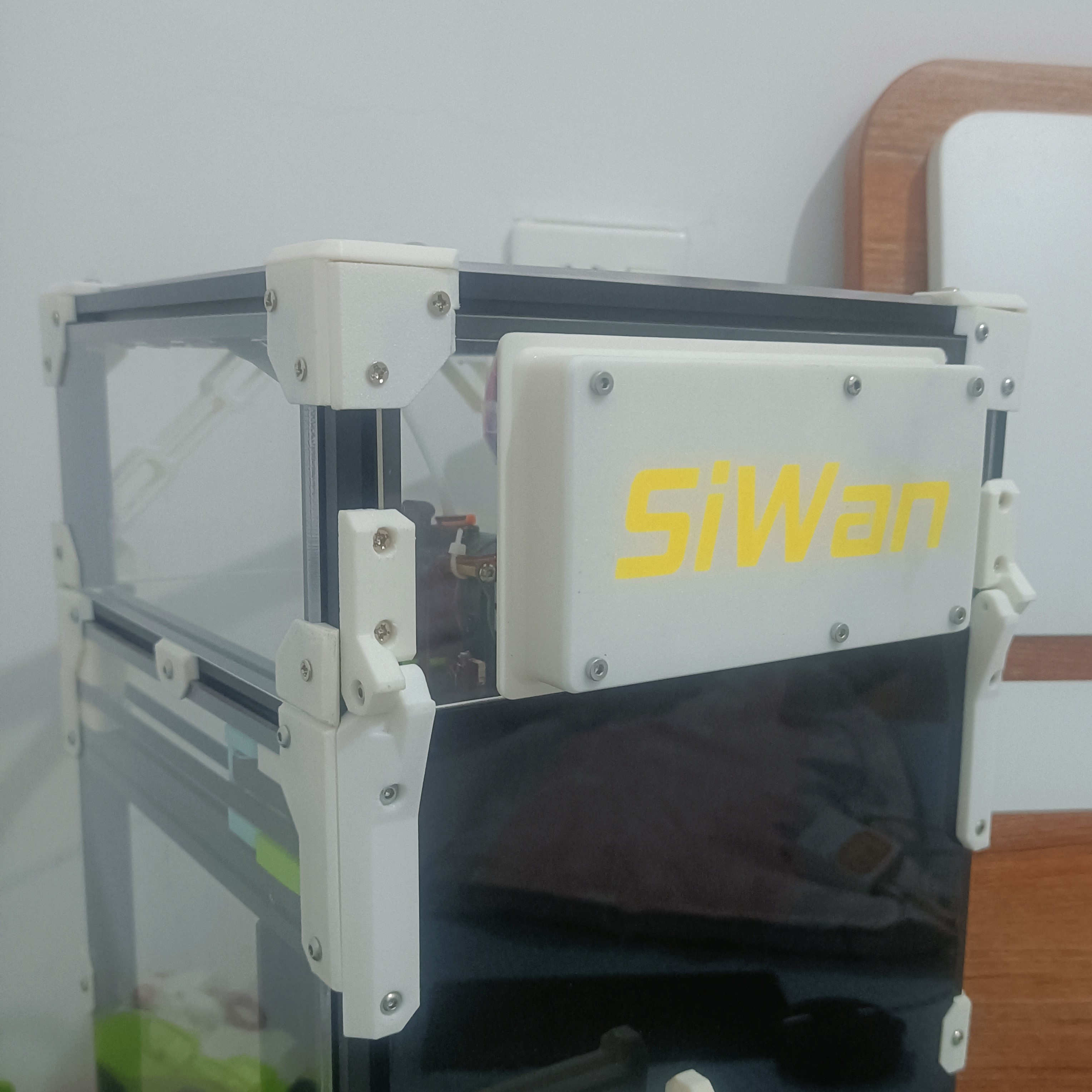
Image 3: Rear view Image
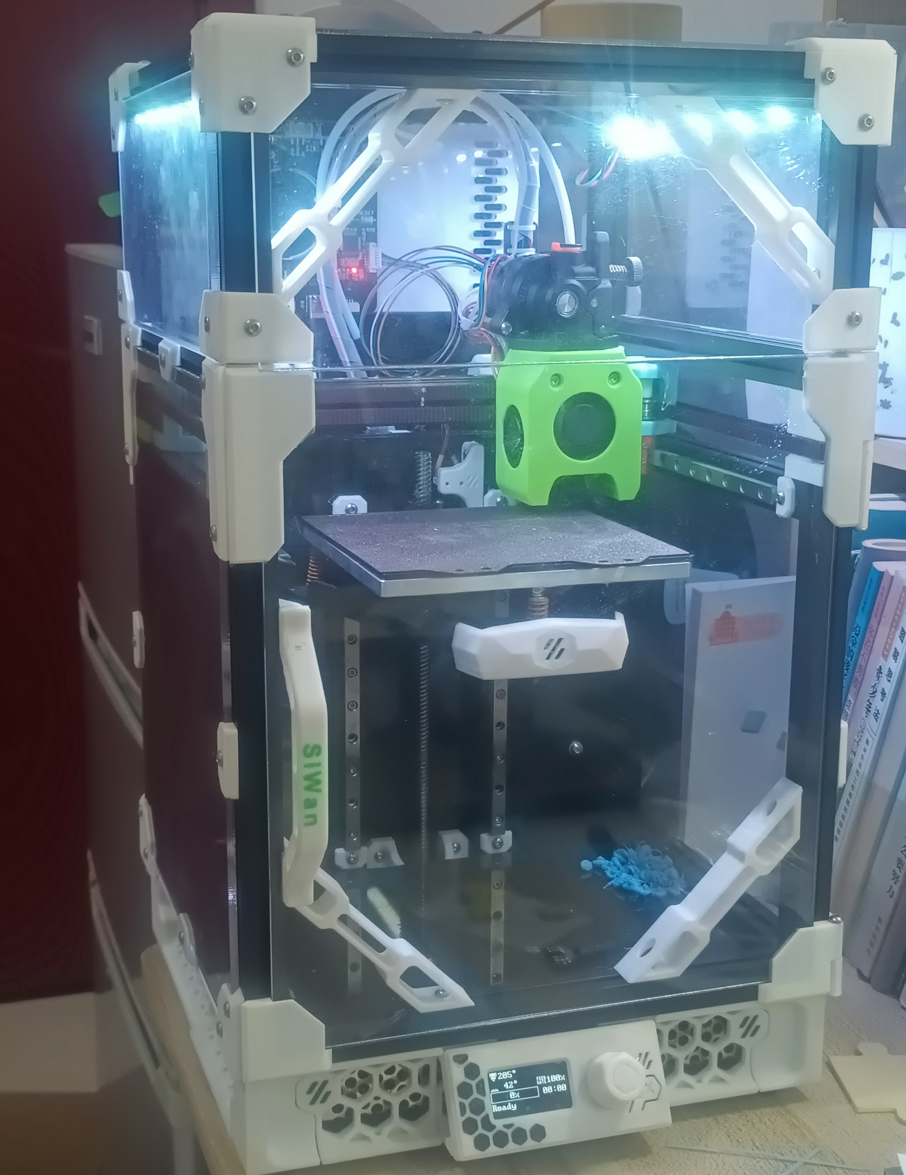
4: Overall image Additional notes for
the competition logo verification project version : During the actual product verification process, some unreasonable aspects were found. It is recommended to refer to these points before replicating. The following are the points to be improved: 1. The fan noise is relatively loud. It is recommended to purchase a relatively high-speed, silent fan, because it is often on during printing, and quietness is relatively important. 2. Fan connection to the motherboard: The currently used XH2.54 vertical mounting interface has a relatively short cable at the connection point. Tweezers are needed for assembly, and the cable needs to be cut to a suitable length, which is about 5cm. Wire cutters or cutting it shorter is needed to re-solder it at the fan pad. Additionally, if your motherboard doesn't have enough USB ports, it's recommended to use an expansion board (P2) to expand only the fan (temperature is selectable, but some pins are not ADC pins). 3. Currently, it uses TYPE-C for connection, but there is slight structural interference (when the cover is closed). It is recommended to purchase a raised TYPE-C female connector. Modifications may be made later. USB Type-C 16P female connector, horizontal mounting pad, 1.0/2.5/4.3mm height, four-pin USB connector on the board. 4. The temperature and humidity sensor (AHT20) cannot be connected to Klipper for linkage (this is a major bug). Currently, NTC thermal linkage or linkage based on printing status is used. Welcome to contact us for update suggestions . Disclaimer: This open-source version is for exchange and learning purposes only. Do not use it for commercial purposes. For electrical operations, please perform wiring operations with professional knowledge and safety awareness. I am not responsible for any losses or consequences , nor am I responsible for any Q&A or guidance. Q&A and guidance depend on individual circumstances. If you are doing DIY, you agree to the above statement . Log V1.0 initial form, major mechanical interference during installation. Version 1.1: Optimized wiring and some interface shapes, improved layout and enhanced system stability. This version is recommended for PCB design.

PDF_#9th LCSC Electronics Design Contest# Klipper_3D Printed Air Circulation System.zip
Altium_#9th LCSC Electronics Design Contest# Klipper_3D Printed Air Circulation System.zip
PADS_#9th LCSC Electronics Design Contest# Klipper_3D Printed Air Circulation System.zip
BOM_#9th LCSC Electronics Design Contest#Klipper 3D Printing Air Circulation System.xlsx
90751
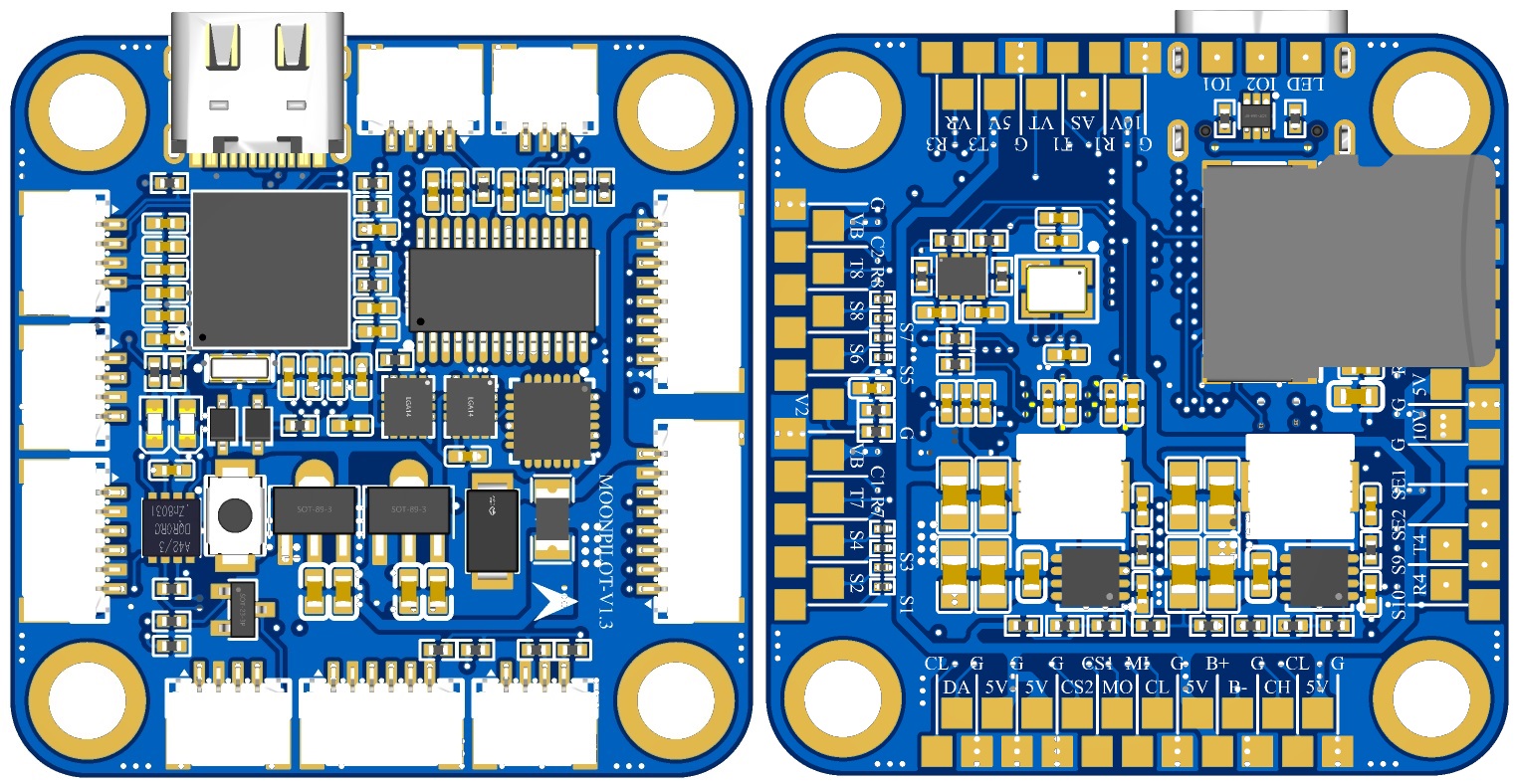
MOONPILOT H743 Flight Controller
MoonPilot is a flight controller that uses the STM32H743VIH6 microcontroller with a main control frequency of up to 480MHz and supports BetaFlight. It adopts a top connector and bottom pad design and has a rich array of interfaces.
MOONPILOT Flight Controller:
A Simulation
Introduction
The MOONPILOT flight controller is an STM32H743-based flight control hardware that supports mainstream flight control systems (BF/INAV/ARDUPILOT). Its features include:
1. Using the STM32H743VIH6 microcontroller with a main frequency up to 480MHz, it is more compatible with flight control systems that have deployed RTOS, in addition to BETAFLIGHT, and can also be used to deploy and verify your own navigation/control algorithms.
2. Nine SH1.0 connectors on the front panel meet the basic requirements for taking off a racing drone, allowing users to launch the aircraft without requiring specific soldering skills; an additional SWD port is designed to meet debugging needs.
3. Dual LDO design, with separate power supplies for the MCU and SENSORS, providing cleaner power input to each sensor.
4. The main/auxiliary inertial measurement units are optional, allowing users to select chips according to their needs (IMU0: ICM42688/ICM42605/MPU6000, IMU1: ICM42688/ICM42605).
5. Equipped with a USB anti-backlash circuit, TVS diodes, and a resettable fuse to enhance flight controller safety.
6. Except for the PWM resistor which uses eight 0201 resistors, all other resistors are packaged in 0402 or larger packages, reducing the difficulty of replication and repair.
External Interfaces
: 1. SWD debugging interface;
2. UART1-4, UART6-8, 7 serial ports in total;
3. PWM/DSHOT 1-4, 5-8, 9-10, of which 1-8 have connectors;
4. CAN bus, SPI bus (with 2 CS pins), I2C bus;
5. LED 1, BEEPER 1;
6. PIN_IO 2;
7. ADC voltage measurement 2, current measurement 2, RSSI 1, AIRSPEED * 1;
8. BEC 5V 2A, 10V (actual output 10.4V) 2A.
Internal interface
MCU
PWM
MCU
SERIAL
MCU
USB/ADC/I2C/LED
MCU
SPI(1/2/4)
MCU
SPI3/CAN
MCU
SWD/PINI
PB0
S1
PE8
Tx7
PA11
D-
PA5
SPI1_SCLK(IMU0)
PB3
SPI3_SCLK
PA14
SWCLK
PB1
S2
PE7
Rx7
PA12
D+
PA6
SPI1_MISO(IMU0)
PB4
SPI3_MISO
PA13
SWDIO
PA0
S3
PA9
Tx1
PC1
CURR1(0-3v3)
PD7
SPI1_MOSI(IMU0)
PB5
SPI3_MOSI
PD10
PINIO1
PA1
S4
PA10
Rx1
PA7
CURR2(0-3v3)
PA13
GYRO1_CS(IMU0)
PD4
SPI3_CS1
PD11
PINIO2
PA2
S5
PD5
Tx2
PC0
VBAT1(1:11)
PB2
GYRO1_EXTI(IMU0)
PE2
SPI3_CS2
-
-
PA3
S6
PD6
Rx2
PA4
VBAT2(1:21)
PB13
SPI2_SCLK(AT7456E)
PC12
SDIO_CLK
-
-
PD12
S7
PD8
Tx3
PC5
RSSI(0-3v3)
PB14
SPI2_MISO(AT7456E)
PD2
SDIO_CMD
-
-
PD13
S8
PD9
Rx3
PC4
AirSpeed(1:2)
PB15
SPI2_MOSI(AT7456E)
PC8
SDIO_D0
-
-
PD14
S9
PE1
Tx8
PB6
I2C1_SCL
PB12
AT7456E_CS(AT7456E)
PC9
SDIO_D1
-
-
PD15
S10
PE0
Rx8
PB7
I2C1_SDA
PE12
SPI4_SCLK(IMU1)
PC10
SDIO_D2
-
-
PE5
S11
PB9
Tx4
PB10
I2C2_SCL(DPS310)
PE13
SPI4_MISO(IMU1)
PC11
SDIO_D3
-
-
PE6
S12
PB8
Rx4
PB11
I2C2_SDA(DPS310)
PE14
SPI4_MOSI(IMU1)
PD1
CAN_Tx
-
-
PA8
LED_STRIP
PC6
Tx6
PE3
LED0
PE15
GYRO2_EXIT(IMU1)
PD0
CAN_Rx
-
-
PA15
BEEPER
PC7
Rx6
PE4
LED1
PE11
GYRO2_CS(IMU1)
PD3
CAN_SILENT
-
-
Connector Wiring
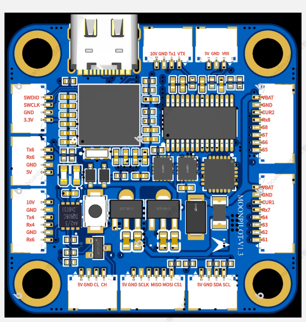
Diagram
Test Progress
2024.08.05---Static testing of connectors: ESC, image transmission, OSD, camera, remote control receiver, and ESC output all functioned normally. 2024.09.02
---Static testing of BEEPER and LED strip showed normal output. 2024.09.20
---Static testing of the SD card black box function showed normal operation. In full-speed recording mode, attitude calculation, attitude control, and OSD outputs were all normal and without any lag. 2024.11.10
---Dynamic flight test: ALong X1 frame, 800mW Panda image transmission, ELRS 2.4G receiver. Black box recording was enabled, variable PWM was used, and all possible configurations were fully utilized. OSD attitude display was smooth and fluid.
Test Flight Video:
MoonPilot H743 Test Flight Record 2024.11.10 (Bilibili video link)
Creation Rationale:
The author has long been engaged in flight control and navigation algorithm-related work, and has used PIXHAWK-2.4.8 (a domestically produced knock-off), Anonymous Flight Controller, and PIXHAWK-4. After analyzing the BETAFLIGHT open-source code, and referring to the pin design of the MATEK-H743 flight controller (this hardware can be directly flashed with MATEKH743 firmware), the preliminary design of MoonPilot was completed.
This flight controller is designed with a straightforward hardware approach, providing significant computational redundancy (EKF, UKF, ADRC, etc.) for students' algorithm design. The on-chip 2MB FLASH is more than sufficient even for deploying an RTOS. An SWD interface is also included to facilitate debugging of the flight controller's software and hardware.
When designing the IMU circuit, considering the current transition from the discontinued MPU6000 to the ICM42688P, and given that the MPU6000's performance remains strong, redundant pads were incorporated into the IMU0 design.
If you have any questions about the design of this flight controller, please feel free to discuss them in the comments section. Hardware experts are also welcome to review the design of this flight controller.
betaflight_4.6.0_STM32H743_MOONPILOT.hex
MOONPILOT-SCH.pdf
PDF_【Spark Project】MOONPILOT H743 Flight Controller & ESC Kit.zip
Altium_【Spark Project】MOONPILOT H743 Flight Controller & ESC Kit.zip
PADS_【Spark Project】MOONPILOT H743 Flight Controller & ESC Kit.zip
BOM_【Spark Project】MOONPILOT H743 Flight Controller & ESC Kit.xlsx
90752
WiFi smart power strip retrofit based on ESP8266 and Buffalo Cloud
I bought a cheap power strip from Taobao and modified it into a Wi-Fi controlled smart power strip. I used an 8266 chip and a TC118S chip to control a magnetic latching relay to achieve on/off switching.
This project involves
modifying a purchased standard power strip to allow individual control of each socket via Buffalo Cloud.
0805 surface-mount capacitors and 1206 surface-mount resistors are used for easy soldering.
This power strip uses 220V AC power. DIY projects and actual use may involve risks of electric shock, burns, and other potential injuries, disabilities, or death. Please strictly follow safety regulations and take adequate precautions. Minors should operate under the supervision of a guardian. By using this solution, you acknowledge the safety risks; please ensure you have sufficient knowledge before proceeding. You are solely responsible for any losses or consequences incurred, and I assume no legal liability.
I am not a professional in electronics hardware or software; I am merely an amateur enthusiast. Therefore, I may lack basic hardware and software knowledge. Any errors in the circuit diagrams or code are sincerely appreciated and I would be grateful for any corrections.
Materials required
(BOM is automatically generated, please refer to this list for details)
: Power strip: Round power strip, Quantity 1;
WiFi module: ESP8266 (this project uses E103-W01 module, compatible with ESP12F, etc.), Quantity 1;
Magnetic latching relay: Hongfa magnetic latching relay HF3F-L-05-1HL1T, Quantity 3;
Relay control chip: TC118S, Quantity 3;
ACDC power module: Hailingke HLK-5M05, Quantity 1;
Inductor: Common mode inductor UU9.8 20MH, Quantity 1;
Capacitor: Safety capacitor X2 275V 0.1uF lead spacing 10mm, Quantity 1;
Aluminum electrolytic capacitor 10V 220uf 5x11, Quantity 1;
0805 SMD capacitor 22uF, Quantity 2;
0805 SMD capacitor 100nF, Quantity 7;
Fuse: 5x20 fuse tube 250V 1A, Quantity 1;
5x20 fuse holder, quantity 1;
1206 resettable fuse 6V 1.1A, quantity 1;
Resistor: 10D561K varistor 560V, quantity 1;
1206 SMD resistor 1kΩ, quantity 3;
1206 SMD resistor 10kΩ, quantity 5;
Linear regulator: AMS1117-3.3 SOT-89, quantity 1;
Diode: Schottky diode SS14, quantity 1;
0805 LED, quantity 3;
**The power strip uses Y-type screws, a Y-type screwdriver is required!**
The software code
is for reference only.
/*
* Bafa Technology
* Supports network configuration via Bafa app and mini-program. Long press the button to reconfigure the network.
*/
#include
#include
#include
#include
#include
#include
WiFiClient client_bemfa_WiFiClient;
HTTPClient http_bemfa_HTTPClient;
// Bafa cloud server address (default is fine)
#define TCP_SERVER_ADDR "bemfa.com"
// Server port, TCP Maker Cloud port 8344
#define TCP_SERVER_PORT "8344"
//*****Places that can be modified******//
String aptype = "001"; // 001 socket type, 002 light type, 003 fan type, 004 sensor, 005 air conditioner, 006 switch, 009 curtain
String Name = "table lamp"; // Device nickname, can be modified at will
String verSion = "3.1"; // 3.1 is TCP protocol, 1.1 is MQTT protocol,
String room = ""; // Room. For example, living room, bedroom, etc., are empty by default.
int adminID = 0; //It is fine to leave it empty by default. Enterprise ID, recommended for enterprise users. The device will be automatically bound to the enterprise. See section 5.17 of the access documentation for how to obtain the ID.
`int protoType = 3; // 3 is the TCP device port 8344, 1 is the MQTT device`
`const int Pin1 = 13;
const int Pin1_2 = 12; const
int Pin2 = 16
; const int Pin2_2 = 14;
const int Pin3 = 5;
const int Pin3_2 = 4; // Microcontroller LED pin value, GPIO0 pin. For other development boards, modify to your own pin, for example, modify to D4 on the NodeMCU development board`
`int failCount = 0; // Define the number of failed connections`
`String upUrl = "http://bin.bemfa.com/b/3BcZGJhMGI4ZjJlNThhNDA4MmIwZDI3YTA3YWQ1NWNjOWY=158145183001.bin";` //OTA firmware link, please replace with your own firmware link. If you receive msg=update, start the firmware upgrade.//**********************//
//
Check if this is the first time connecting to WIFI
bool firstWIfiConfig = false;
String topic = "";
//Maximum number of bytes
#define MAX_PACKETSIZE 512
//Set heartbeat value to 30s
#define KEEPALIVEATIME 60 * 1000
//TCP client related initialization, default settings are fine
WiFiClient TCPclient;
String TcpClient_Buff = "";
unsigned int TcpClient_BuffIndex = 0;
unsigned long TcpClient_preTick = 0;
unsigned long preHeartTick = 0; //Heartbeat
unsigned long preTCPStartTick = 0; //Connection
bool preTCPConnected = false;
//Related function initialization
//Connect to WIFI
void doWiFiTick();
void startSTA();
//TCP initialization connection
void doTCPClientTick();
void startTCPClient();
void sendtoTCPServer(String p);
//led control functions
void turnOnLed1();
void turnOffLed1();
void turnOnLed2();
void turnOffLed2(); void turnOnLed3();
void
turnOffLed3();
int httpCode = 0;
String UID = "";
String TOPIC1 = "";
String TOPIC2 = "";
String TOPIC3 = "";
#define HOST_NAME "bemfa"
char config_flag = 0;
#define MAGIC_NUMBER 0xAA
/**
* Structure used to store network configuration information
*/
struct config_type {
char stassid[32];
char stapsw[64];
char cuid[40];
char ctopic[32];
uint8_t reboot;
uint8_t magic;
};
config_type config;
char packetBuffer[255]; // Send data packets
WiFiUDP Udp;
void saveConfig();
void initWiFi();
void loadConfig();
void restoreFactory();
void waitKey();
void checkFirstConfig();
void apConfig();
// Print logs when the upgrade starts
void update_started() {
Serial.println("CALLBACK: HTTP update process started");
}
// Print logs when the upgrade ends
void update_finished() {
Serial.println("CALLBACK: HTTP update process finished");
}
// During the upgrade, print logs
void update_progress(int cur, int total) {
Serial.printf("CALLBACK: HTTP update process at %d of %d bytes...
", cur, total);
}
// When the upgrade fails, print logs
void update_error(int err) {
Serial.printf("CALLBACK: HTTP update fatal error code %d
", err);
}
/**
* Firmware upgrade function
* Add this function where an upgrade is needed, for example, add updateBin() in setup;
* Principle: Obtain remote firmware through an HTTP request to achieve the upgrade
*/
void updateBin() {
Serial.println("start update");
WiFiClient UpdateClient;
ESPhttpUpdate.onStart(update_started); // When the upgrade starts,
ESPhttpUpdate.onEnd(update_finished); // When the upgrade ends ,
ESPhttpUpdate.onProgress(update_progress); // When the upgrade is in progress,
ESPhttpUpdate.onError(update_error); // When the upgrade fails,
t_httpUpdate_return ret = ESPhttpUpdate.update(UpdateClient, upUrl);
switch (ret) {
case HTTP_UPDATE_FAILED: // When the upgrade fails
Serial.println("[update] Update failed.");
break;
case HTTP_UPDATE_NO_UPDATES: //When there is no update
Serial.println("[update] Update no Update.");
break;
case HTTP_UPDATE_OK: //When the update is successful
Serial.println("[update] Update ok.");
break;
}
}
/**
* Store network configuration information
*/
void saveConfig() {
int rand_key;
uint8_t mac[6];
WiFi.macAddress(mac);
config.reboot = 0;
EEPROM.begin(256);
uint8_t* p = (uint8_t*)(&config);
for (int i = 0; i < sizeof(config); i++) {
EEPROM.write(i, *(p + i));
}
EEPROM.commit();
}
Ticker delayTimer;
void delayRestart(float t) {
delayTimer.attach(t, []() {
ESP.restart();
});
}
/**
* Initialize WiFi information and connect to the router network
*/
void initWiFi() {
if (WiFi.status() != WL_CONNECTED) {
WiFi.disconnect(); // Disconnect
WiFi.mode(WIFI_STA); // STA mode
WiFi.begin(config.stassid, config.stapsw); // Connect to the router
}
int num = 0;
while (WiFi.status() != WL_CONNECTED && num < 120) { // Check if the connection is successful
delay(500);
num = num + 1;
Serial.print(".");
}
Serial.println("wifi config ok");
}
/**
* Load the stored information and check if the factory reset has been performed after 5 restarts
*/
uint8_t* p = (uint8_t*)(&config);
void loadConfig() {
uint8_t mac[6];
WiFi.macAddress(mac);
EEPROM.begin(256);
for (int i = 0; i < sizeof(config); i++) {
*(p + i) = EEPROM.read(i);
}
config.reboot = config.reboot + 1;
if (config.reboot >= 4) {
restoreFactory();
}
if (config.magic != 0xAA) {
config_flag = 1;
} for (int i = 0; i < sizeof(config); i++) { EEPROM.write(i, *(p + i)); } EEPROM.commit(); delay(2000); EEPROM.begin(256);
config.reboot = 0; for (int i = 0; i < sizeof(config); i++) { EEPROM.write(i, *(p + i)); } EEPROM.commit(); delay(2000); } /** * /* Restore factory settings and clear stored Wi-Fi information */ void restoreFactory() { Serial.println("Restore Factory....... "); config.magic = 0x00; strcpy(config.stassid, ""); strcpy(config.stapsw,"");
strcpy(config.cuid, "");
strcpy(config.ctopic, "");
saveConfig();
delayRestart(1);
while (1) {
delay(100);
}
}
/*
First network configuration check for WIFI, save WIFI configuration information, and create a topic
*/
void checkFirstConfig()
{
if(firstWIfiConfig){
// Set target URL
http_bemfa_HTTPClient.begin(client_bemfa_WiFiClient,"http://pro.bemfa.com/vs/web/v1/deviceAddTopic");
// Create JSON object
StaticJsonDocument<200> jsonDoc;
jsonDoc["uid"] = config.cuid;
jsonDoc["name"] = Name;
jsonDoc["topic"] = topic;
jsonDoc["type"] = protoType;
jsonDoc["room"] = room;
jsonDoc["adminID"] = adminID;
jsonDoc["wifiConfig"] = 1; //Required field
// Converts the JSON object to a string
String jsonString;
serializeJson(jsonDoc, jsonString);
http_bemfa_HTTPClient.addHeader("Content-Type", "application/json; charset=UTF-8");
// Send the request
int httpCode = http_bemfa_HTTPClient.POST(jsonString);
if (httpCode == 200) {
Serial.println("POST succeeded with code:");
Serial.println(httpCode);
String payload = http_bemfa_HTTPClient.getString();
Serial.println(payload);
// Parse the JSON data
StaticJsonDocument<200> doc;
DeserializationError error = deserializeJson(doc, payload);
if (error) {
Serial.print(F("deserializeJson() failed: "));
Serial.println(error.c_str());
}
int code = doc["code"];
if (code == 0) {
int resCode = doc["data"]["code"];
if(resCode == 40006 || resCode ==0 ){
String docUID = doc["uid"];
Serial.print("create topic ok:");
Serial.println(topic);
if(firstWIfiConfig){
config.reboot = 0;
config.magic = 0xAA;
saveConfig();
}
}else{
Serial.println(" config ERROR....");
}
} else {
Serial.println(" config ERROR....");
}
} else if (httpCode != 200) {
Serial.println("POST failed with code:");
Serial.println(httpCode);
} else {
Serial.println("Unknown error");
}
http_bemfa_HTTPClient.end();
}
}
void apConfig(String mac){
if(config_flag == 1){
WiFi.softAP("bemfa_"+mac);
Udp.begin(8266);
Serial.println("Started Ap Config...");
}
topic = mac;
while(config_flag){//如果未配网,开启AP配网,并接收配网信息
int packetSize = Udp.parsePacket();
if (packetSize) {
Serial.print("Received packet of size ");
Serial.println(packetSize);
Serial.print("From ");
IPAddress remoteIp = Udp.remoteIP();
Serial.print(remoteIp);
Serial.print(", port ");
Serial.println(Udp.remotePort());
int len = Udp.read(packetBuffer, 255);
if (len > 0) {
packetBuffer[len] = 0;
}
Serial.println("Contents:");
Serial.println(packetBuffer);
StaticJsonDocument<200> doc;
DeserializationError error = deserializeJson(doc, packetBuffer);
if (error) {
Serial.print(F("deserializeJson() failed: "));
Serial.println(error.f_str());
return;
}
int cmdType = doc["cmdType"].as();;
if (cmdType == 1) {
const char* ssid = doc["ssid"];
const char* password = doc["password"];
const char* token = doc["token"];
strcpy(config.stassid, ssid);
strcpy(config.stapsw, password);
strcpy(config.cuid, token);
//收到信息,并回复
String ReplyBuffer = "{"cmdType":2,"productId":""+topic+"","deviceName":""+Name+"","protoVersion":""+verSion+""}";
Udp.beginPacket(Udp.remoteIP(), Udp.remotePort());
Udp.write(ReplyBuffer.c_str());
Udp.endPacket();
}else if(cmdType == 3){
config_flag = 0;
firstWIfiConfig = true;
WiFi.softAPdisconnect(true);
}
}
}
}
/**
* 检查是否需要airkiss配网
*/
void waitKey() {
if (config_flag == 1) {
apConfig(TOPIC1);//加载ap
}
}
/*
*发送数据到TCP服务器
*/
void sendtoTCPServer(String p) {
if (!TCPclient.connected()) {
Serial.println("Client is not readly");
return;
}
TCPclient.print(p);
Serial.println("[Send to TCPServer]:String");
Serial.println(p);
preHeartTick = millis(); //Heartbeat timer starts, data needs to be sent every 60 seconds
}
/*
*Initialize and establish connection with the server
*/
void startTCPClient() {
if (TCPclient.connect(TCP_SERVER_ADDR, atoi(TCP_SERVER_PORT))) {
Serial.print("
Connected to server:");
Serial.printf("%s:%d
", TCP_SERVER_ADDR, atoi(TCP_SERVER_PORT));
String tcpTemp = ""; //Initialize string
tcpTemp = "cmd=1&uid=" + UID + "&topic=" + TOPIC3+","+ TOPIC2 +","+ TOPIC1 + "
"; //Construct subscription command
Serial.println(tcpTemp);
sendtoTCPServer(tcpTemp); //Send subscription command
tcpTemp = ""; //Clear
preTCPConnected = true;
TCPclient.setNoDelay(true);
failCount = 0;
} else {
failCount = failCount+1;
if(failCount>2){ //If the connection fails 3 times, restart the system
delayRestart(0);
}
Serial.print("Failed connected to server:");
Serial.println(TCP_SERVER_ADDR);
TCPclient.stopAll();
preTCPConnected = false;
}
preTCPStartTick = millis();
}
/*
*Check data, send heartbeat
*/
void doTCPClientTick() {
//Check if disconnected, reconnect
if (WiFi.status() != WL_CONNECTED) return;
if (!TCPclient.connected()) { //Reconnect if disconnected
if (preTCPConnected == true) {
preTCPConnected = false;
preTCPStartTick = millis();
Serial.println();
Serial.println("TCP Client disconnected.");
TCPclient.stopAll();
} else if (millis() - preTCPStartTick > 1 * 1000) //Reconnect
TCPclient.stopAll();
startTCPClient();
} else {
if (TCPclient.available()) { //Receive data
char c = TCPclient.read();
TcpClient_Buff += c;
TcpClient_BuffIndex++;
TcpClient_preTick = millis();
if (TcpClient_BuffIndex >= MAX_PACKETSIZE - 1) {
TcpClient_BuffIndex = MAX_PACKETSIZE - 2;
TcpClient_preTick = TcpClient_preTick - 200;
}
}
if (millis() - preHeartTick >= KEEPALIVEATIME) { //Keep heartbeat
Serial.println("--Keep alive:");
sendtoTCPServer("cmd=0&msg=keep
");
}
}
if ((TcpClient_Buff.length() >= 1) && (millis() - TcpClient_preTick >= 200)) { //data ready
TCPclient.flush();
Serial.print("Rev string:
TcpClient_Buff.trim(); // Remove leading and trailing spaces
Serial.println(TcpClient_Buff); // Print the received message
String getTopic = "";
String getMsg = "";
if (TcpClient_Buff.length() > 15) { // Note that TcpClient_Buff is just a string, initialized at the beginning above String TcpClient_Buff = "";
// At this point, the push command will be received, the command is roughly cmd=2&uid=xxx&topic=light002&msg=off
int topicIndex = TcpClient_Buff.indexOf("&topic=") + 7; // C language string search, find the position of &topic= and move 7 positions. If you don't understand, you can search for C language string search on Baidu
int msgIndex = TcpClient_Buff.indexOf("&msg="); // C language string search, find the position of &msg=
getTopic = TcpClient_Buff.substring(topicIndex, msgIndex); // C language string truncation, truncates to topic. (For those unfamiliar, search "C language string truncation" on Baidu)
getMsg = TcpClient_Buff.substring(msgIndex + 5); // C language string truncation, truncates to message
Serial.print("topic:------");
Serial.println(getTopic); // Prints the truncate topic value
Serial.print("msg:--------");
Serial.println(getMsg); // Prints the truncate message value
}
if(getTopic == TOPIC1){ // If it's a message sent to topic1
if(getMsg == "on"){ // If it's a message ==
turnOnLed1();//topic1 on
}else if(getMsg == "off"){ // If it's a message ==
turnOffLed1();//topic1 off
}
}else if(getTopic == TOPIC2){ // If it's a message sent to topic1
if(getMsg == "on"){ // If it's a message ==
turnOnLed2(); // topic2 on
} else if(getMsg == "off"){ // If it's a message ==
turnOffLed2(); // topic2 off
}
} else if(getTopic == TOPIC3){ // If it's a message sent to topic1
if(getMsg == "on"){ // If it's a message ==
turnOnLed3(); // topic3 on
} else if(getMsg == "off"){ // If it's a message ==
turnOffLed3(); // topic3 off
}
} else if (getMsg == "update") {
Serial.println("[update] Update Start......");
updateBin();
}
TcpClient_Buff = "";
TcpClient_BuffIndex = 0;
}
}
void startSTA() {
WiFi.disconnect(); // Disconnect
WiFi.mode(WIFI_STA); // STA mode
WiFi.begin(config.stassid, config.stapsw); // Connect to router
}
/***************************************************************************
WIFI
******************************************************************************/
/*
WiFiTick
checks if WiFi needs initialization.
Checks if WiFi is connected. If the connection is successful, starts the TCP Client
to control the indicator light.
*/
void doWiFiTick() {
static bool startSTAFlag = false;
static bool taskStarted = false;
static uint32_t lastWiFiCheckTick = 0;
if (!startSTAFlag) {
startSTAFlag = true;
startSTA();
Serial.printf("Heap size:%d
", ESP.getFreeHeap());
}
//未连接1s重连
if (WiFi.status() != WL_CONNECTED) {
if (millis() - lastWiFiCheckTick > 1000) {
lastWiFiCheckTick = millis();
}
taskStarted = false;
}
//连接成功建立
else {
if (taskStarted == false) {
taskStarted = true;
Serial.print("
Get IP Address: ");
Serial.println(WiFi.localIP());
startTCPClient();
}
}
}
//打开继电器
void turnOnLed1() {
Serial.println("Turn ON1");
digitalWrite(Pin1, HIGH);
digitalWrite(Pin1_2, LOW);
delay(500);
digitalWrite(Pin1, HIGH);
digitalWrite(Pin1_2, HIGH);
delay(500);
}
//关闭继电器
void turnOffLed1() {
Serial.println("Turn OFF1");
digitalWrite(Pin1, LOW);
digitalWrite(Pin1_2, HIGH);
delay(500);
digitalWrite(Pin1, LOW);
digitalWrite(Pin1_2, LOW);
delay(500);
}
void turnOnLed2() {
Serial.println("Turn ON2");
digitalWrite(Pin2, HIGH);
digitalWrite(Pin2_2, LOW);
delay(500);
digitalWrite(Pin2, HIGH);
digitalWrite(Pin2_2, HIGH);
delay(500);
}
void turnOffLed2() {
Serial.println("Turn OFF2");
digitalWrite(Pin2, LOW);
digitalWrite(Pin2_2, HIGH);
delay(500);
digitalWrite(Pin2, LOW);
digitalWrite(Pin2_2, LOW);
delay(500);
}
void turnOnLed3() {
Serial.println("Turn ON3");
digitalWrite(Pin3, HIGH);
digitalWrite(Pin3_2, LOW);
delay(500);
digitalWrite(Pin3, HIGH);
digitalWrite(Pin3_2, HIGH);
delay(500);
}
void turnOffLed3() {
Serial.println("Turn OFF3");
digitalWrite(Pin3, LOW);
digitalWrite(Pin3_2, HIGH);
delay(500);
digitalWrite(Pin3, LOW);
digitalWrite(Pin3_2, LOW);
delay(500);
}
// 初始化,相当于main 函数
void setup() {
Serial.begin(115200);
pinMode(Pin1, OUTPUT);
digitalWrite(Pin1, LOW); //写入默认状态
pinMode(Pin1_2, OUTPUT);
digitalWrite(Pin1_2, LOW); //写入默认状态
pinMode(Pin2, OUTPUT);
digitalWrite(Pin2, LOW); //写入默认状态
pinMode(Pin2_2, OUTPUT);
digitalWrite(Pin2_2, LOW); // Write the default state
pinMode(Pin3, OUTPUT);
digitalWrite(Pin3, LOW); // Write the default state
pinMode(Pin3_2, OUTPUT);
digitalWrite(Pin3_2, LOW); // Write the default state
Serial.println("Beginning...");
TOPIC1 = WiFi.macAddress().substring(8); // Get the MAC address for the theme
TOPIC1.replace(":", "1"); // Remove the colon
TOPIC1 = TOPIC1 + aptype;
TOPIC2 = WiFi.macAddress().substring(8); // Get the MAC address for the theme
TOPIC2.replace(":", "2"); // Remove the colon
TOPIC2 = TOPIC2 + aptype;
TOPIC3 = WiFi.macAddress().substring(8); // Get the MAC address for the theme
TOPIC3.replace(":", "3"); // Remove the colon
TOPIC3 = TOPIC3 + aptype;
loadConfig();
waitKey();
initWiFi();
// getUid(topicMac, false);
checkFirstConfig();
UID = config.cuid; // Assign UID
}
// Loop
void loop() {
doWiFiTick(); // Check WiFi
doTCPClientTick(); // TCP message reception
}
Note:
Due to the large current, exposed copper areas of the PCB can be soldered as appropriate
. This project uses 220V AC mains power, please operate with caution!
Actual
PCB:

Soldering front:

Soldering back:
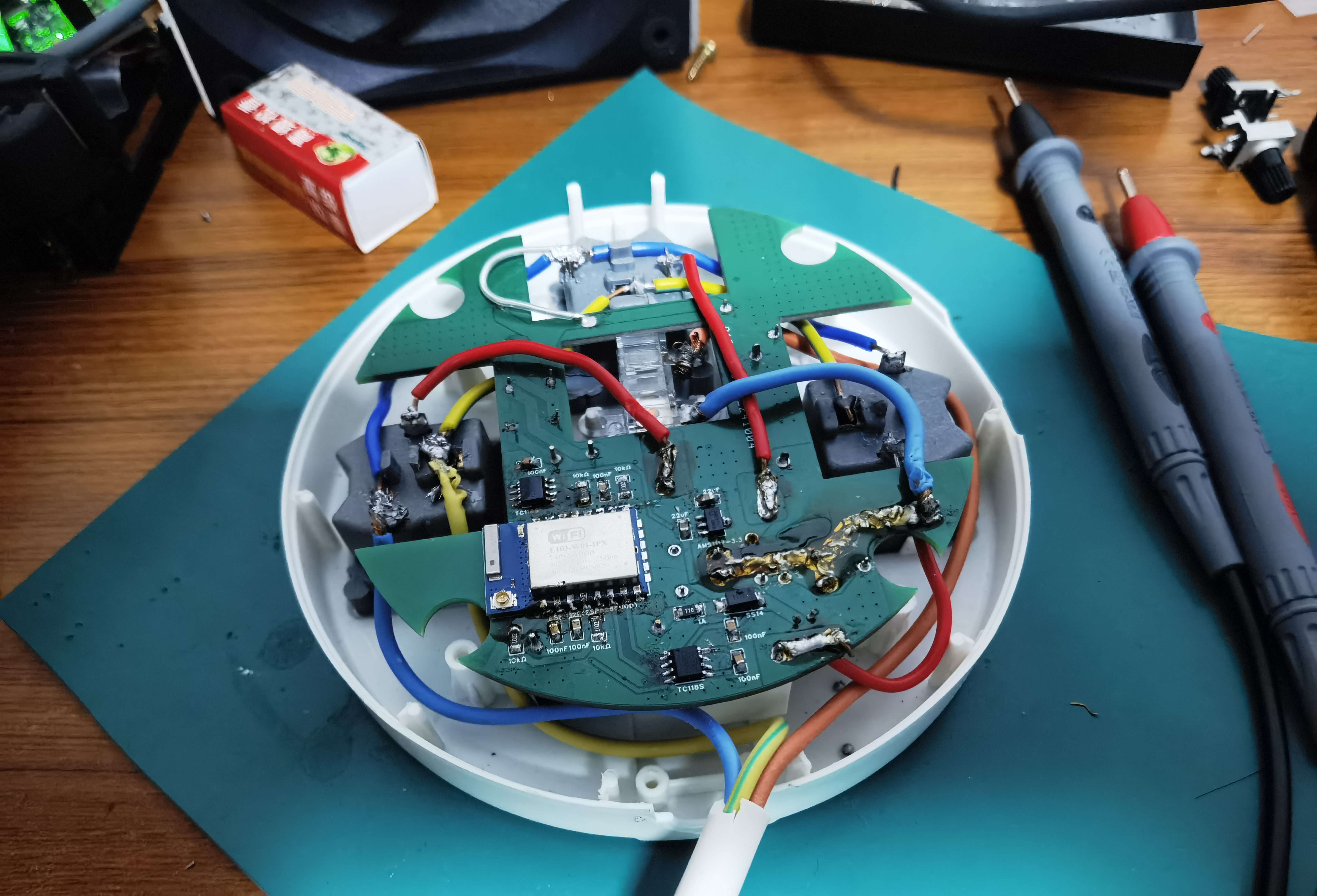
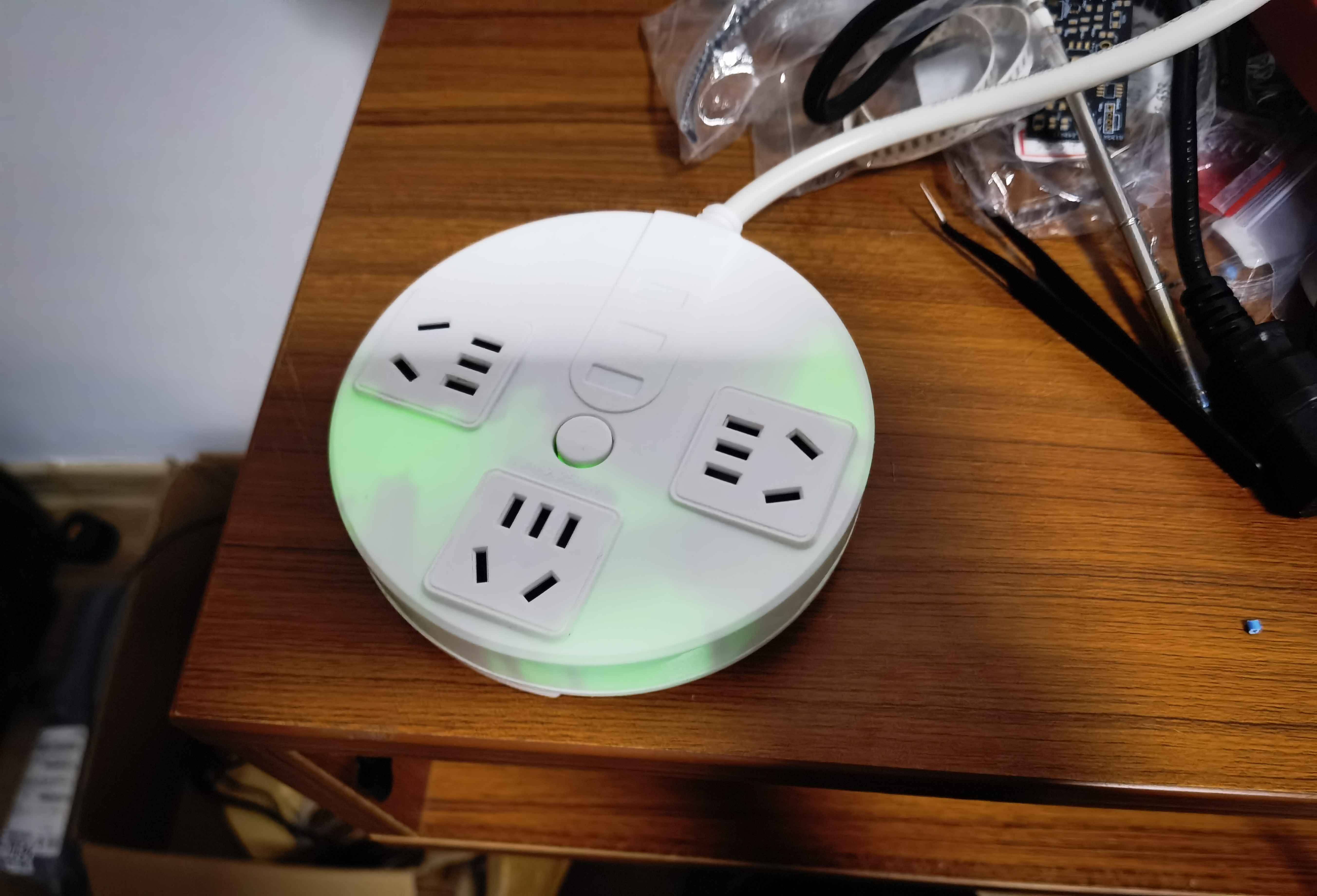
Complete assembly:
Lighting up:
References
This project references the following projects or web pages, and we are very grateful.
Project:
New National Standard Five-Hole Metering Socket 10A
Smart Power Strip
Data:
AP Distribution Network 2.0, Automatic Distribution Network Transmission Key
Bafa Cloud Access Document
HF3F-L-05-1HL1T Datasheet
TC118S Datasheet
HLK-5M05 Datasheet
PDF_WiFi Smart Power Strip Retrofit Based on ESP8266 and Buffalo Cloud.zip
Altium_WiFi Smart Power Strip Retrofit Based on ESP8266 and Buffalo Cloud.zip
PADS_WiFi Smart Power Strip Retrofit Based on ESP8266 and Buffalo Cloud.zip
BOM_WiFi Smart Power Strip Retrofit Based on ESP8266 and Buffalo Cloud.xlsx
90753
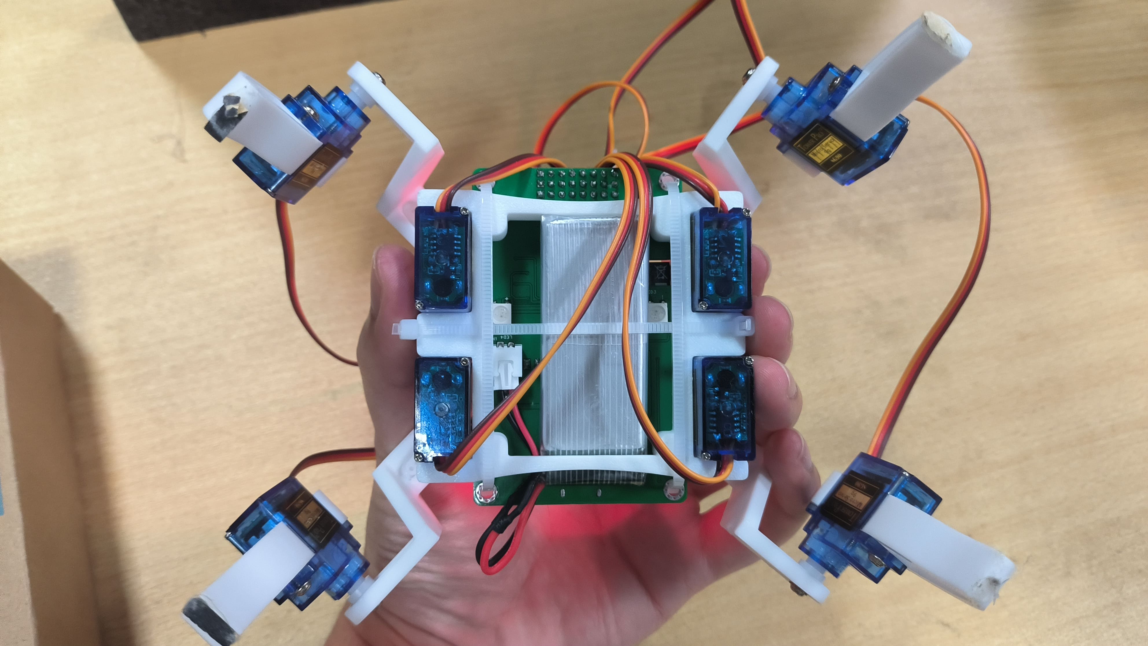
ESP32 Quadruped Robot - Controlled via UDP via Mobile App - With OTA Over-the-Air Download
This quadruped robot, controlled by an ESP32 microcontroller, can be controlled via a mobile app using UDP. It supports AP or STAION modes, network configuration, and OTA (Over-The-Air) download functionality. Attachments include: a current function list, the program's bin file, and the mobile app's APK file.
Video Link:
My video is this
quick jump
1. Project Introduction
2. Project Functions
3. Project Parameters
4. Hardware Description
5. Microcontroller Program Description
6. Mobile APP Program Description
7. My GitHub Repository
8. Precautions
9. Assembly Process
10. Physical Object Image
Project Introduction
This project is a quadruped robot design based on the ESP32 microcontroller. From project creation to writing this article, it took a total of 7 days, starting from the existing gait.
Main Functions: Executes 16 different actions, coordinated with facial expressions. It can be remotely controlled via UDP through a mobile APP,
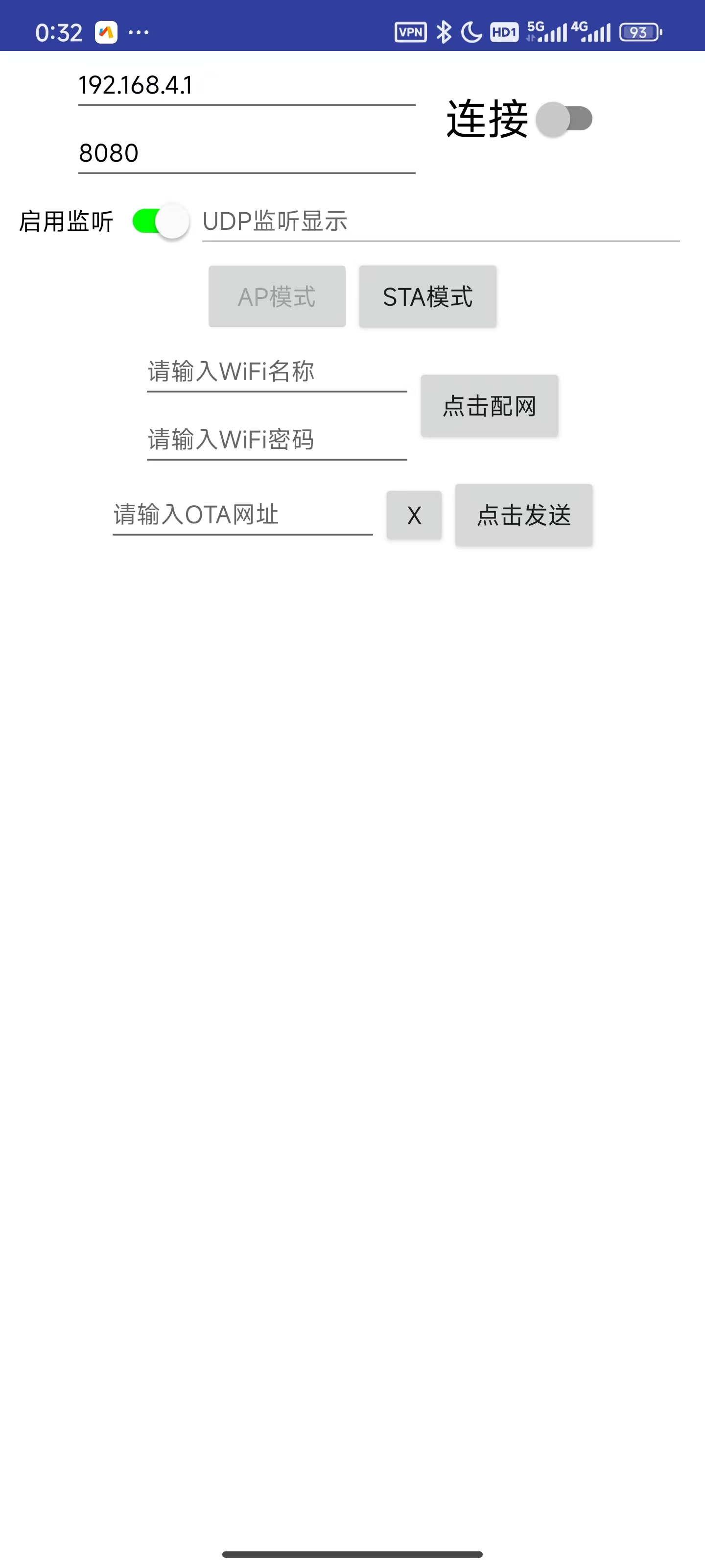
using AP mode or STAION mode. It can also be configured for network access via the mobile app without opening or modifying the program.
It has OTA over-the-air download function for convenient updates. The OTA URL can be written through the mobile app, and the OTA update requires bin files hosted on the Buffalo Cloud platform.
Project Functions
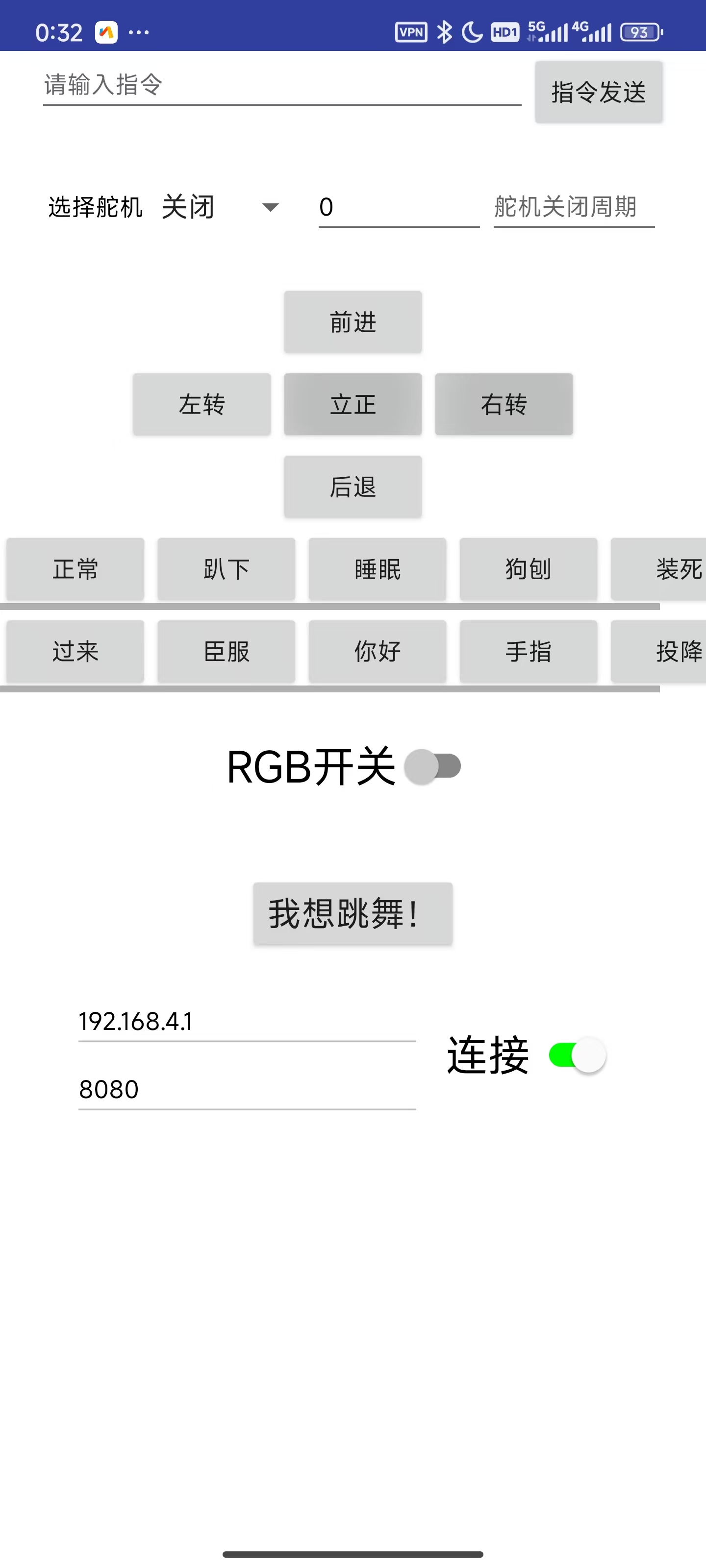
16 Robot Actions: Stand at attention, move forward, move backward, turn left, turn right, normal, lie down, sleep, doggy paddle, play dead, come here, surrender, hello, finger, surrender, dance.
Action or function commands can be transmitted directly to the microcontroller via UDP using a mobile app or NetAssist on a computer.
Function commands include: motion control, single servo control, PWM frequency control, network configuration, configuring the OTA update URL, switching the ESP32's WiFi mode, and triggering the OTA update program.
Action commands include: 16 basic actions, suspending and resuming RGB lighting tasks, displaying the local IP address, and displaying 9 emoticons in a polling manner.
A 0.96-inch OLED screen displays emoticons and prompts: 9 emoticons mapped to 16 actions, displaying the local IP address, indicating successful network configuration, displaying OTA update in progress, and showing the WiFi mode selection menu.
Two WS2812 chips are currently used for the lighting function.
Four buttons, EN, BOOT, Key1, and Key2, can be used together to switch WiFi modes and trigger OTA updates.
The OTA update function facilitates remote update downloads.
The project parameters
use a PCA9685 chip to control 8 servos and communicate with the microcontroller via I2C, saving pins and computing power.
The power supply design uses readily available charge/discharge modules, saving design time. The
four-legged connectors were purchased ready-made from Taobao. The
servo motors used are the cheapest and worst available, the SG90.
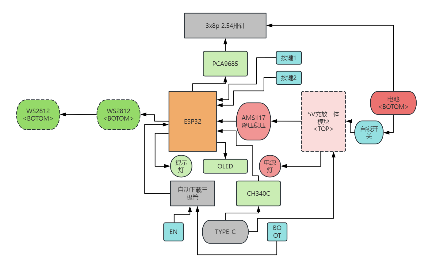
Hardware Specifications:
This project consists of the following parts: power supply, main control unit, servo motor control unit, button control unit, and functional components.
Hardware Connection Diagram :
Darker colors represent the bottom layer, lighter colors represent the top layer, and the lightest color represents something on top of the top layer.
Microcontroller Program Description:
Initially, I considered using Bluetooth for its convenient connection, easy microcontroller programming, and convenient mobile app development. However, it would be too large. Before enabling Bluetooth, the compiled code used 22% of the flash memory (default program allocation is 1.2MB). Enabling Bluetooth immediately increased the flash memory to 90%, making it difficult to write subsequent code. Therefore, I ultimately used UDP.
Arduino's built-in libraries are like this; using IDF would be much better.
This program uses a FreeRTOS multi-tasking architecture. Tasks communicate with each other using task notifications, including:
`void ota_task(void *param)
` // OTA task, which can be created by other tasks to trigger OTA updates; `
void udp_control(void *param)
` // UDP task, used to receive incoming commands, parse them, and notify other tasks to process them. It can also broadcast the local IP address, WiFi mode, and RGB status when starting the task, so that the microcontroller can receive and parse the commands even if it doesn't know the mobile app's IP address;
`void motion_task(void *param)
` // Servo control task, receives notifications from the UDP task and executes corresponding actions;
`void oled_task(void *param)
` // OLED control task, receives notifications from the UDP task and executes corresponding displays. It can also display a menu via buttons to notify UDP to restart and switch WiFi modes;
`void ws2812_task(void *param)
` // RGB lighting task, simply executes lighting tasks, which can be suspended or resumed by commands to switch RGB displays;
`void setup()` `
void loop()`
// In setup, we create the necessary tasks and initializations. Then, we delete tasks in loop to save memory.
OTA uses Buffalo Cloud servers for bin file hosting; you can refer to this blog for related tutorials.
Some complex processes have been written as classes; main.cpp contains the main flow.
Because this project was written quickly, it hasn't been aesthetically pleasing, so reading it might be a bit inconvenient.
For detailed program content and introductions, please see my GitHub repository. I'll probably write more detailed code features in the readme later.
I might add comments to the code later when I have time. I don't like writing many comments for such a small project; you can use an AI plugin in VSCode to help with comments. Currently, I'm using CodeGeeX; it's not particularly powerful, but it works quite well, and most importantly, it's free!
You can see from my commits that there aren't many; they're mostly for adding features, not much optimization. The AI2
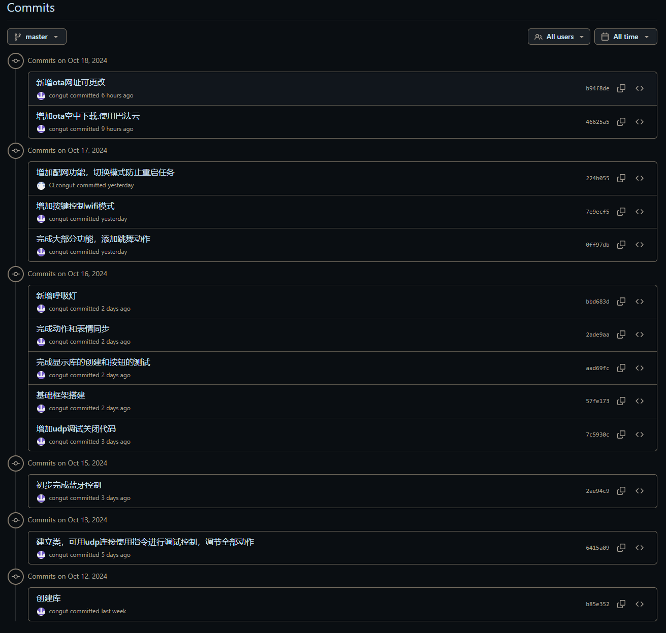
mobile app
project files will also be in the GitHub repository; only the current version of the APK file is posted here.
You can see that the aia file is in the appinventor2 folder in the default master branch.
Using App Inventor 2 for graphical programming development is very user-friendly for beginners with no Android development experience.
I used the original MIT website instead of a domestic, unmaintained site; I'm not sure if the project will be compatible.
The only thing using a UDP extension is this:
The graphical programming interface is too large to screenshot, so I won't post it here. I have screenshots of the software on a mobile phone.
Main controls:
//Command sending section, including the command input box and send button
//Single servo control section, also using the above command sending button.
//5 movement actions: four-way movement and attention, 10 display actions
//RGB switch
//I want to dance! Action 16
//UDP required remote IP and remote port input boxes (automatically entered, or manually) and connection switch
//UDP is not a one-to-one connection like TCP, so the main function of this connection button is to switch panel content
//UDP listening switch and listening display box, which are program-controlled
//AP mode and STA mode buttons, corresponding to AP mode and STA mode on the microcontroller
//Network configuration: WiFi name and WiFi password input boxes, click the network configuration button
//OTA URL input box and send box, used to update the OTA URL.
My GitHub repository
notes:
short-term project, the content is rather rough, there may be strange bugs, no beautification, and the functions are not very complete.
The first download requires a physical connection to the serial port for platformIO download or direct download of the bin file. After that, it can be downloaded over the air via OTA after connecting to the network without the physical serial port.
To use the OTA function, you need to flash the OTA firmware, and the Flash allocation must have space for OTA (which is provided by default).
The M3 holes on the PCB don't align with the holes on the base plate, so I used cable ties to bundle the PCB and base plate together.
The servos must match the serial numbers in my video; otherwise, you'll have to modify the code.
If you bought the quadruped robot kit I linked, you'll need to buy 6-hole servos; otherwise, they won't fit and you
won't be able to write the gait. I directly used the link from this uploader's video and modified it slightly; the forward and backward movement is basically stationary.
I haven't tested whether the WiFi name can use Chinese characters, but the entire project is UTF-8 encoded, so it should be fine.
Don't ask me if you can't access the App Inventor 2 website or my GitHub repository.
The assembly process
will be included in the video.
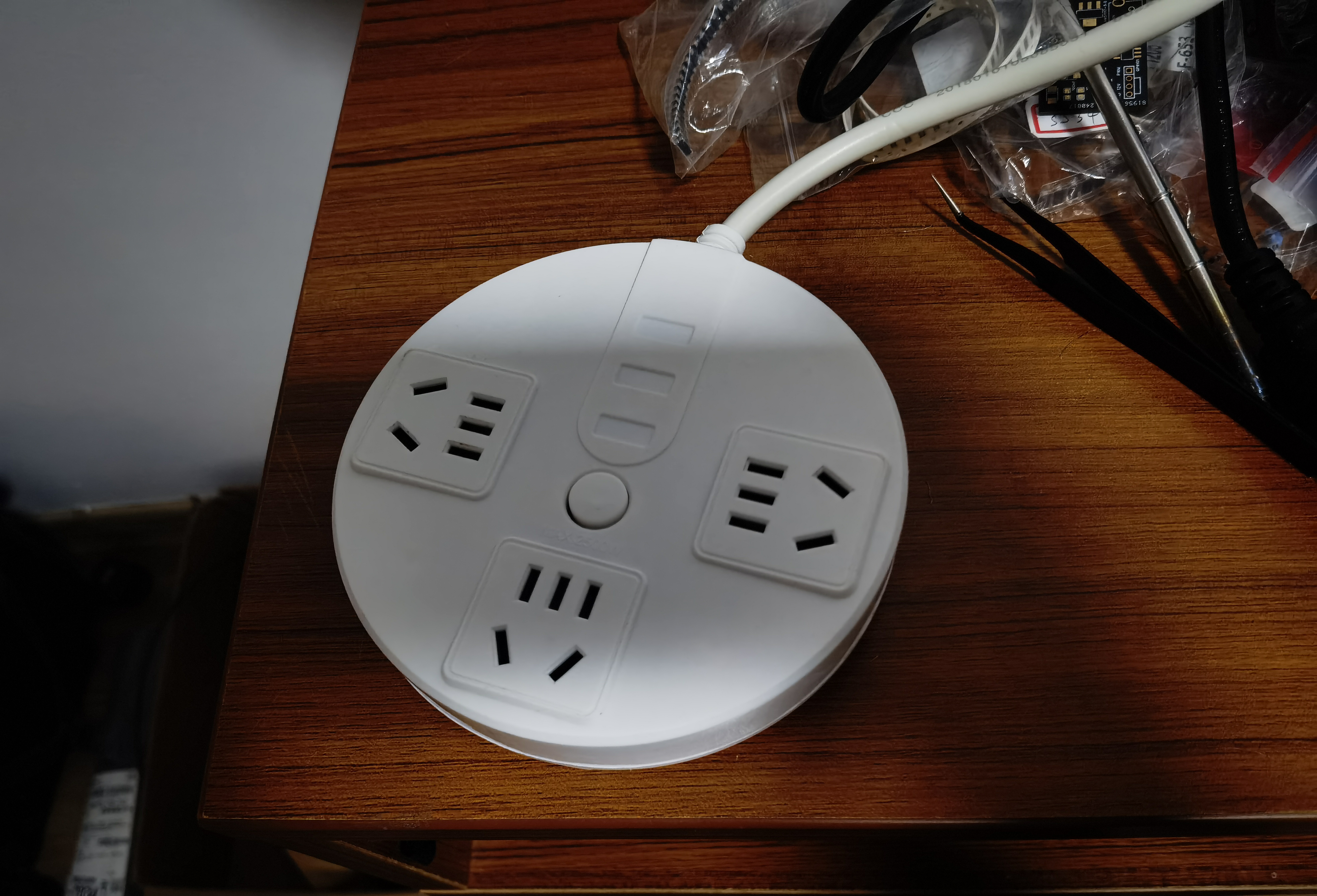
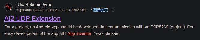
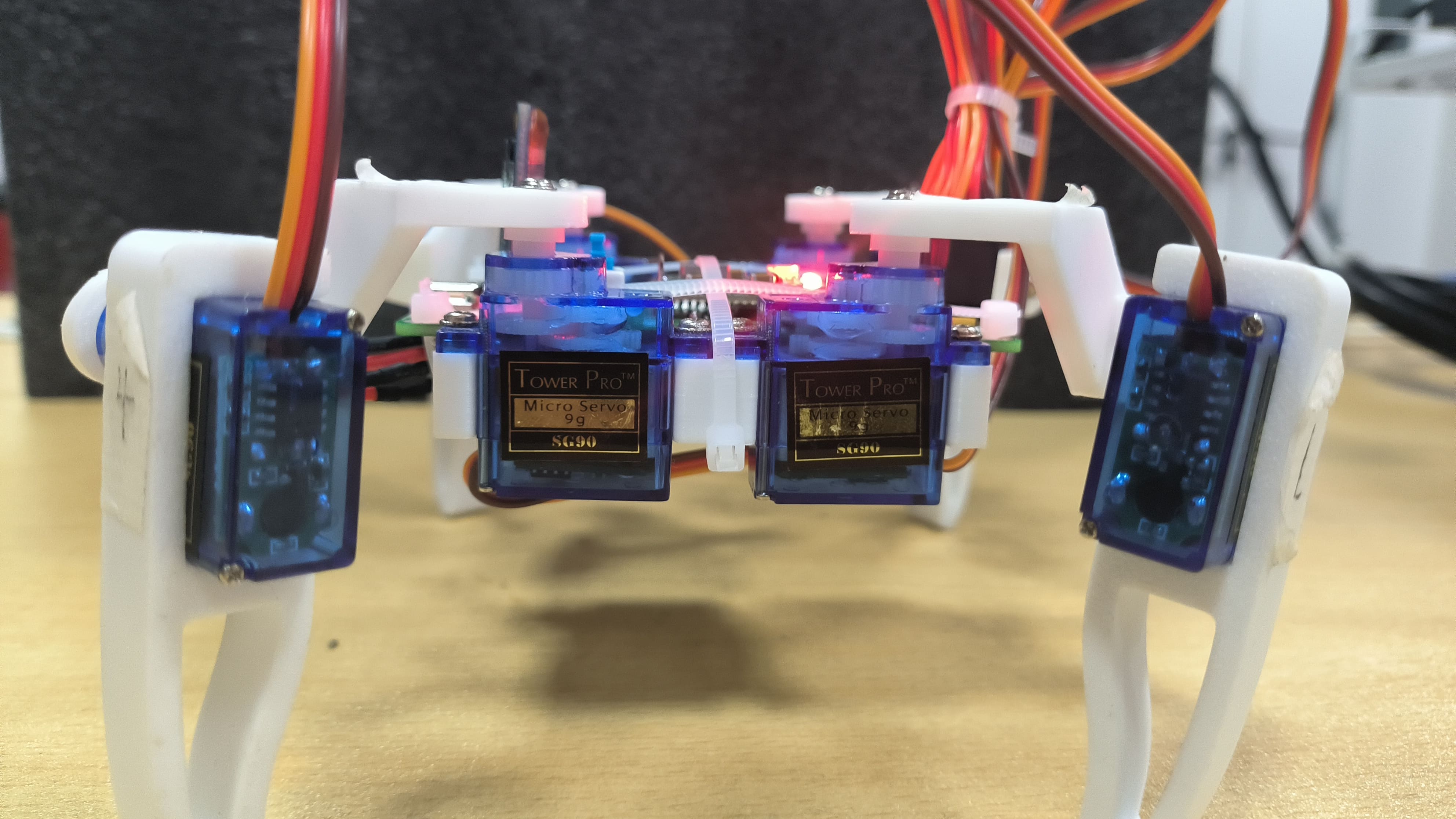
[Images of the actual product:
Front

-
Back
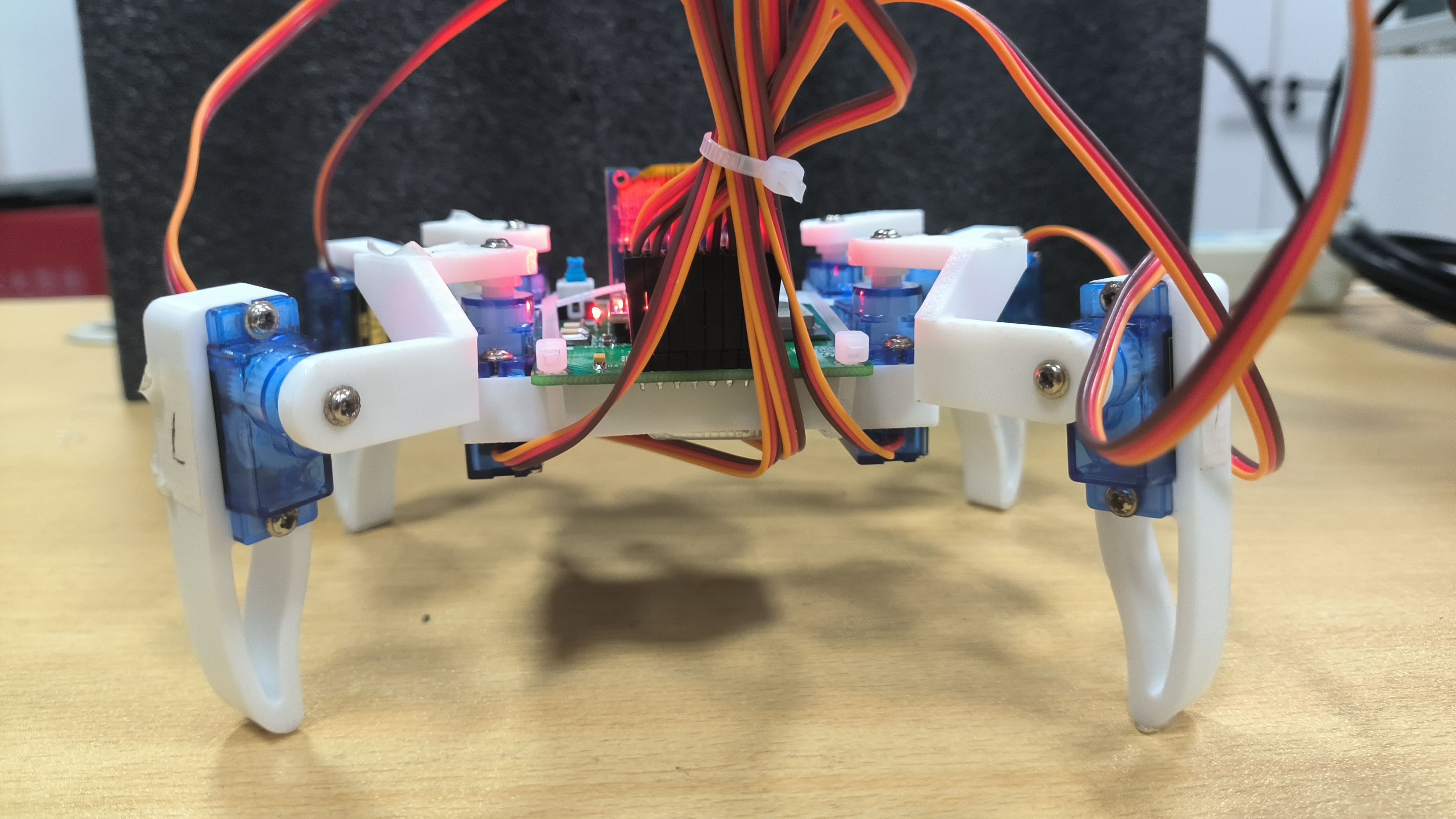
-
Left

-
Right
-
Top
-
Bottom ,
AP Mode,
STA Mode,

Main Control Interface] Finished looking at the main control interface
? Click here to return to the top.
Current functions of the quadruped robot.xlsx
firmware.bin
UDP_CTRL_FFR.apk
PDF_ESP32 Quadruped Robot - Controlled via UDP via Mobile App - With OTA Over-the-Air Download.zip
Altium ESP32 quadruped robot - controlled via UDP mobile app - with OTA over-the-air download.zip
PADS_ESP32 Quadruped Robot - Controlled via UDP via Mobile App - with OTA Over-the-Air Download.zip
BOM_ESP32 Quadruped Robot - Controlled via UDP via Mobile App - With OTA Over-the-Air Download.xlsx
90754
Intelligent voice chatbot implemented based on esp32-s3-wroom
A smart voice chatbot implemented using esp32-s3-wroom.
Video Link:
Bilibili Video -- Function Demonstration and
Project Introduction
This project is an intelligent voice chatbot implemented based on esp32-s3-wroom. By configuring prompts and voice timbres, you can experience various characters and voices. See Xia Ge's Bilibili videos for examples:
Funny Potato with a Northeastern Accent: https://www.bilibili.com/video/BV1uR26YHEcu/?spm_id_from=333.999.0.0
Flirting with Your Taiwanese-Speaking Ex-Girlfriend: https://www.bilibili.com/video/BV1G4pweCERX/?spm_id_from=333.999.0.0&vd_source=d54d1251b3a2da5a425913a5f429be57
English Teacher: https://www.bilibili.com/video/BV18zsDe1ENN/?spm_id_from=333.999.0.0
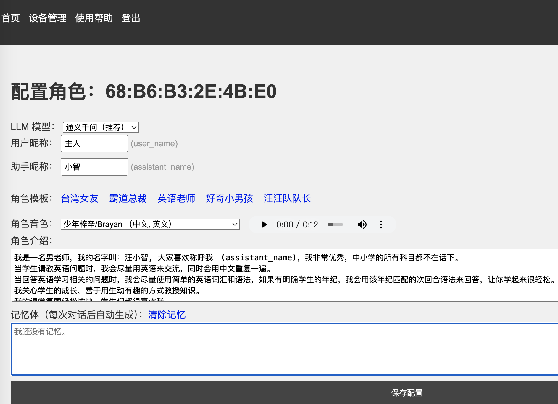
The project's functionality
is based on Xia Ge's server, achieving a low-latency, high-quality voice chat experience. The server-side console: https://xiaozhi.me/ allows you to define the AI's self-awareness through command words. It has voiceprint recognition capabilities and supports speaker configuration. It also has memory capabilities.
The project's firmware
uses Xiaozhi's open-source code: https://github.com/78/xiaozhi-esp32
, only the pinouts are different. You need to modify the pin definitions to build the firmware: Modify the SDK configuration:
CONFIG_AUDIO_DEVICE_I2S_MIC_GPIO_WS=5
CONFIG_AUDIO_DEVICE_I2S_MIC_GPIO_BCLK=4 CONFIG_AUDIO_DEVICE_I2S_MIC_GPIO_DIN=6
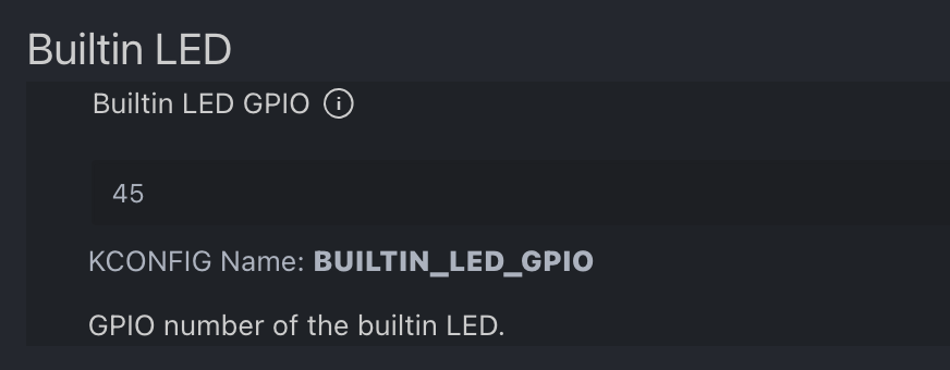
CONFIG_AUDIO_DEVICE_I2S_SPK_GPIO_DOUT =15 CONFIG_AUDIO_DEVICE_I2S_SPK_GPIO_BCLK =16 CONFIG_AUDIO_DEVICE_I2S_SPK_GPIO_WS=17 Alternatively, use the SDK configuration editor (recommended): WS2612 LED pinout: # Builtin LED # CONFIG_BUILTIN_LED_GPIO=45 # end of Built-in LED or modify using the SDK configuration editor (recommended): Xiaozhi AI Chatbot Encyclopedia: https://ccnphfhqs21z.feishu.cn/wiki/F5krwD16viZoF0kKkvDcrZNYnhb Xiaozhi AI Backend Configuration Panel: https://xiaozhi.me/ ( QQ group communication : 946599635)


PDF_Intelligent Voice Chatbot Based on esp32-s3-wroom.zip
Altium_Intelligent Voice Chatbot Based on esp32-s3-wroom.zip
PADS_Intelligent Voice Chatbot Based on esp32-s3-wroom.zip
BOM_Intelligent Voice Chatbot Based on esp32-s3-wroom.xlsx
90755
electronic


 京公网安备 11010802033920号

 AM5TW-2407SZ


