This
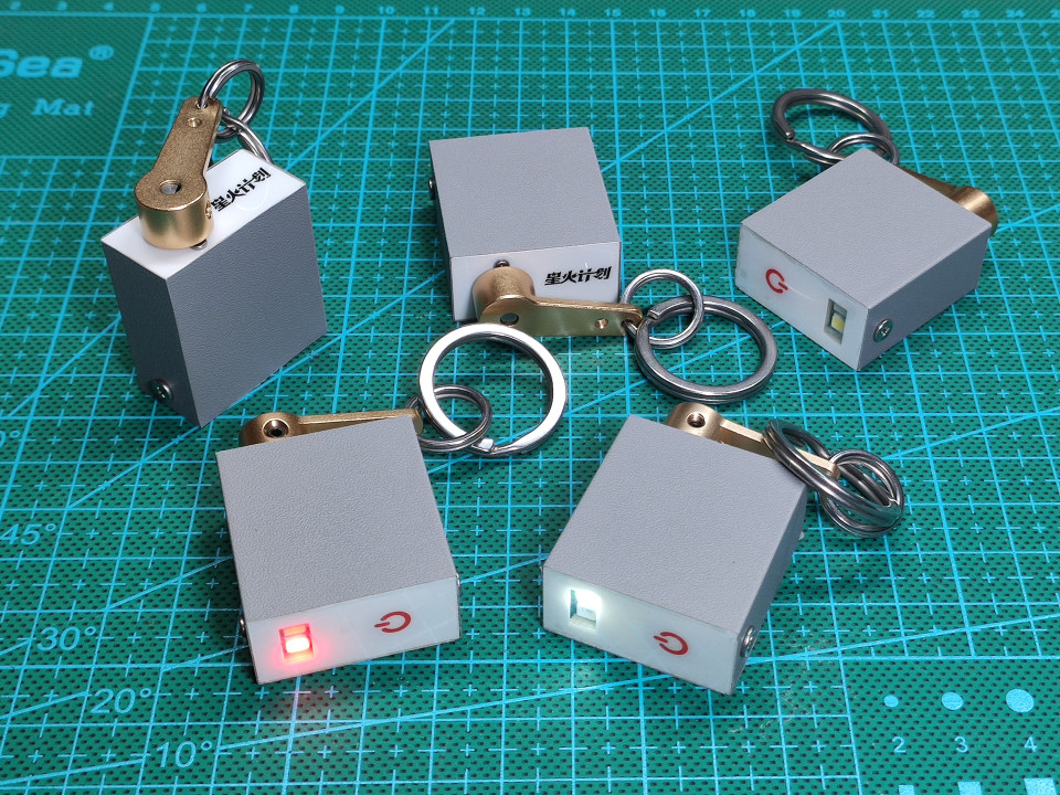
is a multi-functional power-generation flashlight with various lighting modes. It features a red and white dual-color LED, an aluminum alloy body, a comprehensive protection circuit, and a compact, portable design.

Pictures don't do it justice, check out the video
demonstration:
https://www.bilibili.com/video/BV1X7mFY7EkG/
Hardware project:
https://oshwhub.com/code504/edc-power-generation-flashlight
Software code:
The https://gitee.com/dma/edc-generator-flashlight
function description states that for
first-time use or after a long period of inactivity, please rotate the handle to generate electricity. When the battery reaches the minimum usage limit, the white light will flash twice. At this point, you can continue generating electricity or providing illumination .
With the device off, rotating the handle 300 times in 2 minutes will charge it to approximately 60%, and rotating it 450 times in 3 minutes will charge it to approximately 80% (actual generation efficiency may vary slightly depending on the rotation speed).
Continuing to rotate the handle when it is close to full charge will reduce generation efficiency, so it is not recommended to continue generating electricity. Once fully charged, the protection circuit will activate, so there is no need to worry about overcharging the capacitor.
Generating electricity can be done by rotating the handle in either direction, so there is no need to worry about the direction.
When the battery is low, the brightness will gradually decrease and eventually turn off.
The circuit will consume some power during standby after being turned off. The supercapacitor itself also has a self-discharge phenomenon; it is normal for the flashlight to run out of power after a long period of inactivity (more than 3 days).
Button instructions:
Single click turns on the flashlight. After powering on, the default white dim
lighting mode is activated. Single click switches the brightness; single click has no effect on other modes. 4 brightness levels: Low, Medium, and High.
Double-click to switch modes, cycling through the following modes: Illumination, Single Flash (twice per second), Double Flash (twice per second), Strobe, and SOS.
Triple-click to switch colors; white and red are available, and colors can be switched in any mode.
Long press to power off.
Hardware parameters:
Main body dimensions: 43mm*31mm (including the rocker arm, excluding the key ring).
Capacitor specifications: 2.7F, 10F. White
light brightness: Approximately 15 lumens for high brightness
. High brightness illumination duration: Approximately 2 minutes from the start of illumination on a full charge until the brightness noticeably decreases (actual performance may vary slightly depending on component batches).
Power consumption when powered off: Approximately 15uA at 2.6V, theoretical power-off time of over 1 day (actual performance may vary slightly depending on component batches).
Construction instructions
: This small device has fewer than 50 hardware and electronic components, but involves many details, which I will share with you without reservation.
Hardware instructions:
Electronic components
: Supercapacitor.
The theoretical space left for the capacitor is 13mm. x 24mm, the largest usable capacitor size is actually 12.5mm x 20mm.
Capacitor performance may vary between manufacturers. Here is some information I've collected for reference:
| Diameter x Length (mm) | Capacitance (F) |
| --------------- | ---------------- |
| 8 x 20 | 3.3 |
| 10 x 20 | 5 |
| 10 x 20 | 7 (High Capacitance) |
| 12.5 x 20 | 10 |
| 12.5 x 20 | 12 (Medium-High Capacitance) |
| 12.5 x 20 | 15 (High Capacitance) |
Theoretically, the largest supercapacitor you can choose is 12.5x20mm with a 15F capacity. However, this size is much more expensive than smaller capacities, so smaller capacity supercapacitors are recommended.
I chose a 12.5 x 20mm supercapacitor. The energy carried by a 2.7V 10F capacitor
is calculated as E=(1/2)*C*V^2. Theoretically, a 2.7V 10F capacitor carries 36.45J of energy. In reality, due to the capacitor protection circuit, it can only charge to about 2.6V. When the voltage drops below 0.9V, the output power of the boost chip will decrease rapidly. Below 0.5V, the boost chip will not work. Considering the losses of the boost circuit, the actual usable energy is about 60%, about 22J. The power supply voltage for LED high brightness is 3.0V, the current is about 50mA, and the theoretical working time is 22/(3*0.05)=146 seconds. The geared motor specification is N20 geared motor. The following points should be noted when selecting a model: According to Ohm's law for closed circuits, which we learned in second grade, the smaller the internal resistance of the power supply, the higher the efficiency of the power supply. Therefore, we should find a geared motor with the smallest internal resistance of the motor coil to use as a generator. How to check the internal resistance of a motor? Under the condition of constant voltage, the larger the stall current, the smaller the internal resistance. If the seller doesn't provide detailed parameters, check the rotational speed. With a fixed voltage, higher rotational speed means lower internal resistance. If that doesn't work, buy a batch and measure with a multimeter. The internal resistance of this type of motor is generally between a few ohms and tens of ohms. Low internal resistance means high power generation efficiency, but it makes it too easy to turn, feeling like you have too much force but nowhere to apply it, resulting in a poor feel. High internal resistance means you feel "strong" when turning, but low power generation efficiency, with a lot of energy being consumed by the coil's own heat, causing hand fatigue after prolonged use (only a very strong person can turn it continuously for 5 minutes without their hand getting tired). Choose a motor with a 1:100 reduction ratio. A reduction ratio that's too small won't provide enough rotational speed for power generation, while a reduction ratio that's too high can easily damage the primary gear (yes, don't ask, I've already damaged two, both with broken teeth). In summary, I chose a 3V 150rpm motor with a 1:100 reduction ratio. This motor feels better to turn when the capacitor is low on power, and becomes easier to turn when the capacitor is almost fully charged, but the feel is slightly worse (yes, don't ask, I bought over a dozen motors with different parameters and personally tested them all, just to save you from making the same mistakes). However, the feel of a button is subjective, and my opinion is for reference only. You can also choose a geared motor with different speeds to achieve a suitable feel. Other components used include a 1.5mm button height and a BW6101 supercapacitor protection chip (this chip is not available on the LCSC online store at the time of writing and needs to be purchased separately). See the schematic for other components. The PCB board thickness is 1.2mm. 1.2mm. 1.2mm! I'm saying it three times because it's important!
If you plan to redesign the PCB yourself, remember to make the dimensions smaller. Theoretically, the PCB size is 13mm x 28mm. If you draw the PCB according to this size, it will most likely not fit into the casing due to manufacturing errors. So make it slightly smaller, such as 12.8mm x 27.8mm.
The spacing of the pin headers on both sides of the PCB motherboard is carefully adjusted. The spacing of the plastic base of the pin headers should be slightly less than 2.5mm. When assembling the casing, the screw teeth will bite into the plastic base of the pin headers, which cleverly achieves the fixation between the casing and the circuit board. Do not place electronic components near the pin headers to avoid the screws hitting the components.
Metal parts and other parts
panel
printing parameters:
PET, bottom printing, 3M 9448A (universal model), high transparency, no button bulging, thickness 0.2mm.
Panel description:
There are 4 patterns in total for the panel: H-shaped support, front panel, Spark Program logo back panel. Instructions for use:
The two back panels can be selected according to your needs. This work participates in the Spark Program, and I personally use the Spark Program logo back panel. You can also design your own.
The H-shaped panel is used as a support, placed under the front panel. It requires about 4 or 5 layers. Its main function is to prevent excessive deformation of the front panel when pressing the button. Metal
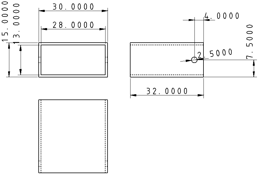
shell
: Find aluminum square tubes for custom processing on an e-commerce platform. The aluminum square tube specifications are 30mm x 15mm, wall thickness 1mm. Have the merchant cut it to 32mm length, and drill a 2.5mm diameter hole on each of the two shorter sides, 4mm from the edge, in the center. Three views are shown below. You can directly send it to the merchant for processing. If needed, surface treatment processes such as sandblasting and anodizing can also be done, but the price will be higher. A vendor I consulted quoted 90 yuan for 10 units without any surface treatment and 260 yuan for 100 units without any surface treatment. This price is for reference only.
To save costs, I chose the option of not doing surface treatment and applying the skin myself. You can also choose a better-looking skin, or if you have the budget, go for sandblasting and anodizing.
The theoretical length of the aluminum square tube is 1.2 (PCB thickness) * 3 + 2.5 (pin header height) + 1.5 (button height) + 15 (motor height) + 9 (gearbox height) = 31.6mm.
In reality, because the PCB has a solder mask layer, copper layer, and silkscreen layer, the thickness will be slightly thicker. In addition, there are assembly errors and processing errors, so I simply rounded it to 32mm, which is also convenient for processing. If you want the best, you can consider making it 31.8mm.
Other Parts
Name Specifications Quantity Reference Price
Aluminum
Alloy
Servo Arm Hole 3mm None 1 4 Yuan Screws M1.6 Length 3mm or 4mm is acceptable, longer ones will hit the gears of the reduction motor 2 100 Pieces 2 Yuan Self-Tapping Screws M2.5 Length 4mm or 5mm is acceptable, longer ones will hit the components on the PCB. You can also buy similar sizes such as M2.3 or M2.6, etc. M2 is too small to screw in 2 100 Pieces 3 Yuan Stainless Steel Key Ring 10mm Diameter 10mm, you can also buy other similar specifications yourself 1 0.5 Yuan Stainless Steel Key Ring 25mm Diameter 25mm, you can also buy other similar specifications yourself 1 0.8 Yuan Notes: Screws and key rings are recommended to be made of stainless steel. Galvanized or painted iron is prone to paint peeling and rusting over time, becoming unsightly. Software Instructions: Please refer to the source code. Each submission includes the latest hex file for direct programming. Programming Instructions: Preparation: The motherboard contains a supercapacitor protection circuit and a boost circuit. Directly using a common 3.3V power supply will cause the supercapacitor protection circuit to activate and the input voltage of the boost circuit to be higher than the output voltage. Therefore, the following programming methods are recommended : Optimal Solution: Use a serial port board that supports voltage adjustment, as shown in the video. Secondary Solution 1: Use a common 3.3V serial port power supply. Connect one or two ordinary diodes in series with VCC to reduce the voltage to below 2.7V and above 1.2V. Remove the diodes after programming. (Disadvantages: The power supply voltage has dropped below 2.7V, but the serial port voltage is still 3.3V, which may damage the microcontroller. STC is relatively robust, so it should not be a big problem.) Alternative Option 2: Use an adjustable power supply to adjust the voltage to 1.2V to 2.6V for power supply (Disadvantages are the same as above. When burning, the adjustable power supply ground, serial port ground, and microcontroller ground must be common ground. This is a common mistake made by beginners and occasionally by experienced users.) Alternative Option 3: Do not solder the supercapacitor discharge resistor and use 3.3V for burning. Solder it after burning is complete (Disadvantages: troublesome) Last resort: Ignore it and burn directly with 3.3V power supply (I have tried it and it can burn. I am not responsible for any damage). Download and settings : STC-ISP official website download address: https://www.stcai.com/gjrj The microcontroller needs to be manually powered on for the first download. In subsequent development and debugging, if it needs to be downloaded again, it does not need to be manually powered on because the code has a function to download without powering on. Upon initial download, select "This download requires hardware option modification" to save power and reduce power consumption. The IRC clock frequency is set to 1.3824MHz. While a lower frequency is possible, the power reduction benefit is minimal. Keep other parameters at their default settings. During subsequent debugging and development, unless the system clock is modified, do not select "This download requires hardware option modification." If serial port errors or incorrect LED blinking frequency occur, the clock frequency is likely incorrect. Remember to check the MCU clock frequency settings in the code and select the correct frequency during programming. For detailed assembly instructions, please refer to the latter half of the video. (This person is really foolish, even detailing the defects!) The circuit diagram uses an ADC for low-voltage and full-charge indications. However, testing revealed significant fluctuations in the ADC output value, making accurate measurement of the supercapacitor voltage difficult. This is difficult to improve within the current extremely limited PCB layout, and this function will no longer be developed. Why not use the BW6101 alarm pin for full-charge detection? Theoretically, it's entirely feasible, and it works fine with an adjustable power supply, but it's not practically feasible. The alarm pin only outputs at 2.75V, but the protection circuit starts discharging at 2.65V. Any extra power generated by manually turning the drill is completely consumed by the protection circuit, making it almost impossible to reach 2.75V. I've tested it; manually turning it simply cannot reach this voltage. Only an external drill can achieve it. Increasing the discharge resistor value of the BW6101 also works, but if the value is too high, the extra power cannot be quickly dissipated, thus negating the purpose of protection.
The shape is too square, and the edges and corners are a bit uncomfortable to handle.


 京公网安备 11010802033920号

 83B1A-A12-K10


