I. IC Overview
1.1 Fluorescent Tube Driver IC -
HV5812 I saw the HV5812 chip in another post on CSDN: The Soviet IV-18 fluorescent digital tube clock development (ИВ-18)
This chip is not widely used, I think for the following two reasons:
it is hard to buy and too expensive (15 RMB per chip on Alibaba, excluding shipping).
For the solution in this article that only uses one HV5812, it can only be dynamically refreshed, so a higher gate voltage is needed.
The solution of ULN2803 Darlington tube + decoder is static refresh, which is brighter at the same gate voltage (dynamic refresh is basically unusable at this voltage).
The reasons for choosing HV5812 as the driver in this article are as follows:
saving PCB area, not needing to use 8 decoders and 8 driver ICs
to complete data transmission using SPI interface, occupying fewer MCU pins.
ULN2803 is an 8-bit Darlington tube, but YS27-3 is a 9-segment tube, so one segment cannot be displayed.
The HV5812 has 20 outputs. Half of the outputs can be used to control the fluorescent tube gate, and the other half can control the fluorescent tube segment code.
1.2 MCU__STM32F103CBT6
is mainly because it is in an LQFP48 package. If there were fewer pins, it would be a QFN package, which is difficult to solder.
When the questioner was doing this, he was not very familiar with ST's microcontrollers, but since they are mainstream, he should gradually learn them to facilitate porting.
1.3 WIFI__ESP-01F
is a small-sized WiFi module from Anxinke, with SPI and serial ports. The WiFi chip is Espressif ESP8285.
This development used the built-in AT firmware. Actually, it is also fine to use this directly as the main controller.
1.4 Clock IC__DS3231
is a very old clock chip. It is used for timing, power-off saving, and generating a 1Hz interrupt.
II. Hardware Circuit
2.1 HV5812
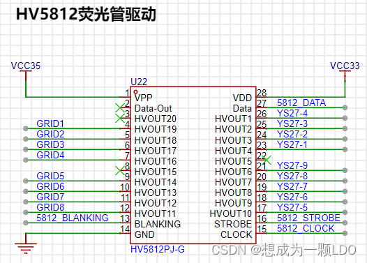
|Network Name| Description|
|--|--|
|VCC35 | VFD Drive Voltage|
| VCC33 | 3.3V |
| GRID1—GRID8| Gates of fluorescent tubes 1-8|
| YS27-1—YS27-9| Segment codes of fluorescent tubes, all fluorescent tube segment codes are cascaded|
| 5812_BLANKING| SPI chip select line, connected to the CS pin of the SPI host|
| 5812_DATA| SPI data line, connected to the MOSI pin of the SPI host|
| 5812_STROBE| Latch, high level latches the current display status|
| 5812_CLK| SPI clock line, connected to the CLK pin of the SPI host|
2.2 STM32F103C8T6

Minimum System:
| Network Name| Description|
|--|--|
|VCC33| 3.3V power supply|
|NRST| Reset|
|SWCLK| SWD clock line|
|SWDIO| SWD data line|
|BOOT0| Boot position selection|
|BOOT1| Boot position selection|
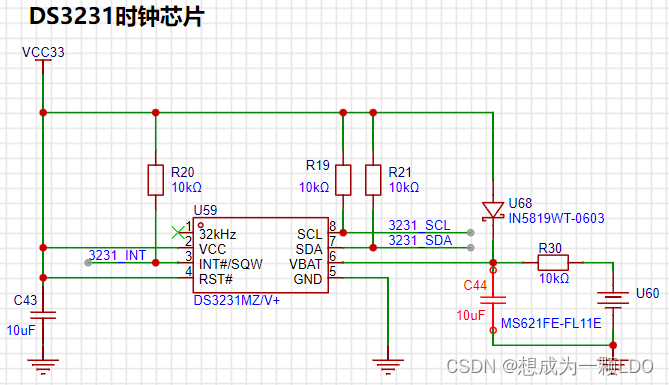
DS3231:
| Network Name| Description|
|--|--|
| 3231_SCL| DS3231 IIC Clock Line|
| 3231_SDA| DS3231 IIC Data Line|
| 3231_INT| DS3231 Interrupt Line| The
DS3231 uses the IIC bus. SCL and SDA require pull-up resistors, as shown in the DS3231 schematic below.
In addition, an interrupt line is connected, which can configure the DS3231 register to output a 1Hz or 32.768kHz interrupt signal. This is mainly to save MCU computing power by reading via IIC after the clock update. Because we are using the persistence of vision effect to dynamically refresh the fluorescent tube, performing time-consuming operations will reduce the refresh rate and significantly affect the viewing experience. Therefore, it is crucial to avoid continuous time-consuming operations when writing the program.
HV5812:
|Network Name| Description|
|--|--|
| 5812_STROBE| HV5812 latch, high level latches the current display status|
| 5812_CLK| HV5812 clock line, connected to the CLK pin of the SPI host|
| 5812_DATA| HV5812 data line, connected to the MOSI pin of the SPI host|
| 5812_BLANKING| HV5812 chip select line, connected to the CS pin of the SPI host|
ESP-01F:
|Network Name| Description|
|--|--|
| ESP_RX| ESP-01F serial port receive pin, connected to the TX pin of the MCU| | ESP_TX|
ESP-01F serial port transmit pin, connected to the RX pin of the MCU|
| ESP_SPI_MOSI| ESP-01F SPI MOSI pin, connected to the MISO pin of the MCU SPI|
| ESP_SPI_MISO| ESP-01F SPI MISO pin, connect to MCU SPI MOSI pin |
| ESP_SPI_CLK | ESP-01F SPI CLK pin, connect to MCU SPI CLK pin |
| ESP_SPI_CS | ESP-01F SPI CS pin, connect to MCU SPI CS pin |
Other:
| Network Name | Description |
|--|--|
| BUZZER | Buzzer, connect to a timer that can output PWM |
| LED1 | LED2 |
| LED2 | LED1 |
| KEY1 | Button1 |
| KEY2 | Button2 |
2.3 ESP-01F
can be connected according to the datasheet. Because it is an RF module, pay attention to the layout considerations in the manual.
A TX/RX pin is reserved for debugging.
When the MCU configures the corresponding pin of the UART for digital function, the external UART (serial-to-USB debugger) will be unusable. Simply disable the digital function when debugging with a PC.

2.4 The DS3231
doesn't require much explanation.
The spare battery on the right uses a charging circuit, which I found on CSDN.
2.5 The XL6007E1 boost circuit
provides the driving voltage for the fluorescent tube. Here, it boosts 5V to 35V.
I didn't actually use 35V (because the tantalum capacitors exploded several times...), but you can adjust it according to your needs.
The YS27-3 manual states that the gate voltage is 12V, and the duty cycle operating voltage is higher (I remember the operating voltage at 50% PWM is 50V).
Since we are using dynamic refresh, a higher voltage is fine, depending on your brightness requirements.
It's worth noting that to save space, the boost circuit uses tantalum capacitors, but their voltage rating is low; the output voltage cannot exceed the rated voltage!
A larger C51 capacitor results in lower power ripple, but also a lower voltage rating! Therefore, it's not easy to find high-voltage tantalum capacitors.
Currently, I'm using a 28V operating voltage and a 47uF 35V tantalum capacitor. I haven't tested the power supply ripple yet, but it works.
(The questioner knows very little about BOOST circuits; this circuit is for reference only. Please be careful during debugging to prevent capacitor explosion.)

2.6 1.2V step-down circuit:
A step-down circuit I found on CSDN. It works in practice.

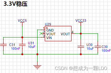
2.7 3.3V voltage regulator circuit.
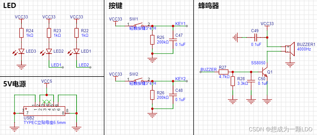
2.8 Buzzer, buttons, and LEDs.
III. Conclusion
: I started working on the fluorescent tube clock during my master's program while staying home during the pandemic. Because I'm a mechanical engineering major, I didn't know anything about circuits at the time.
Looking back, I had a bad habit: I didn't settle down and learn before starting.
Therefore, I always encountered small problems that I couldn't solve, and I would think of giving up;
or I would be a perfectionist and want to redo everything if there was even a small problem.
But even if I didn't do it well, I would always remember to continue after a while.
This is why it took me so long to do it on and off.
Always trying to do it perfectly in one step only takes you further and further away from success.
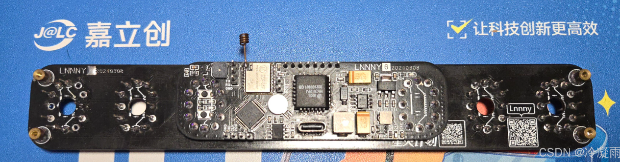
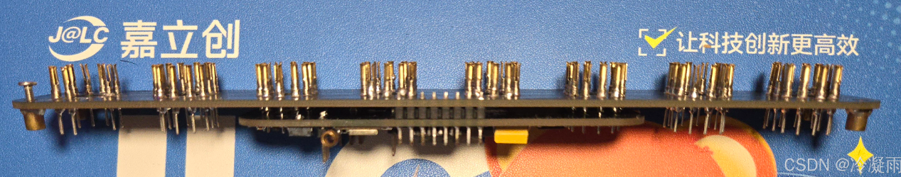
Below are some previous versions.
Although progress is slow, the most interesting part is definitely the process itself!
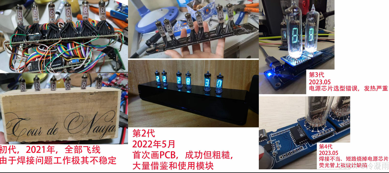
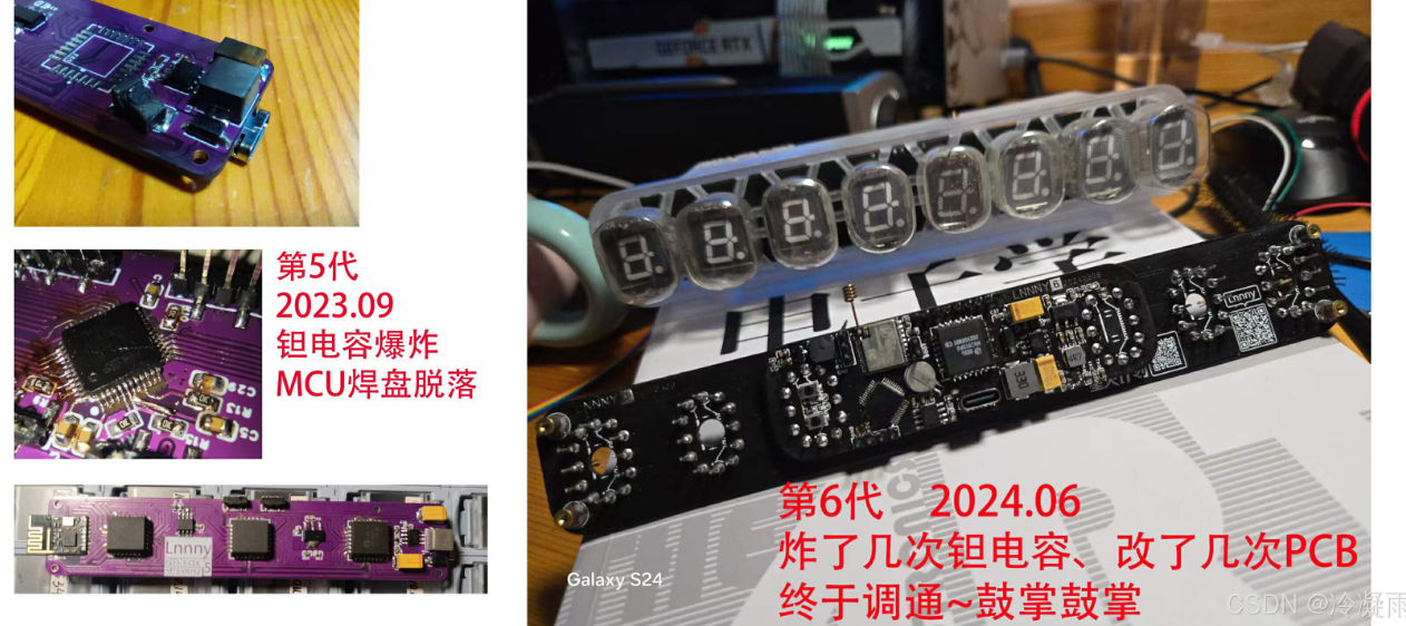
I hope those who are passionate about it can persevere and find joy in every step forward!
Keep up the good work!


 京公网安备 11010802033920号

 56111-G11-18-0500R


