1. Project Description
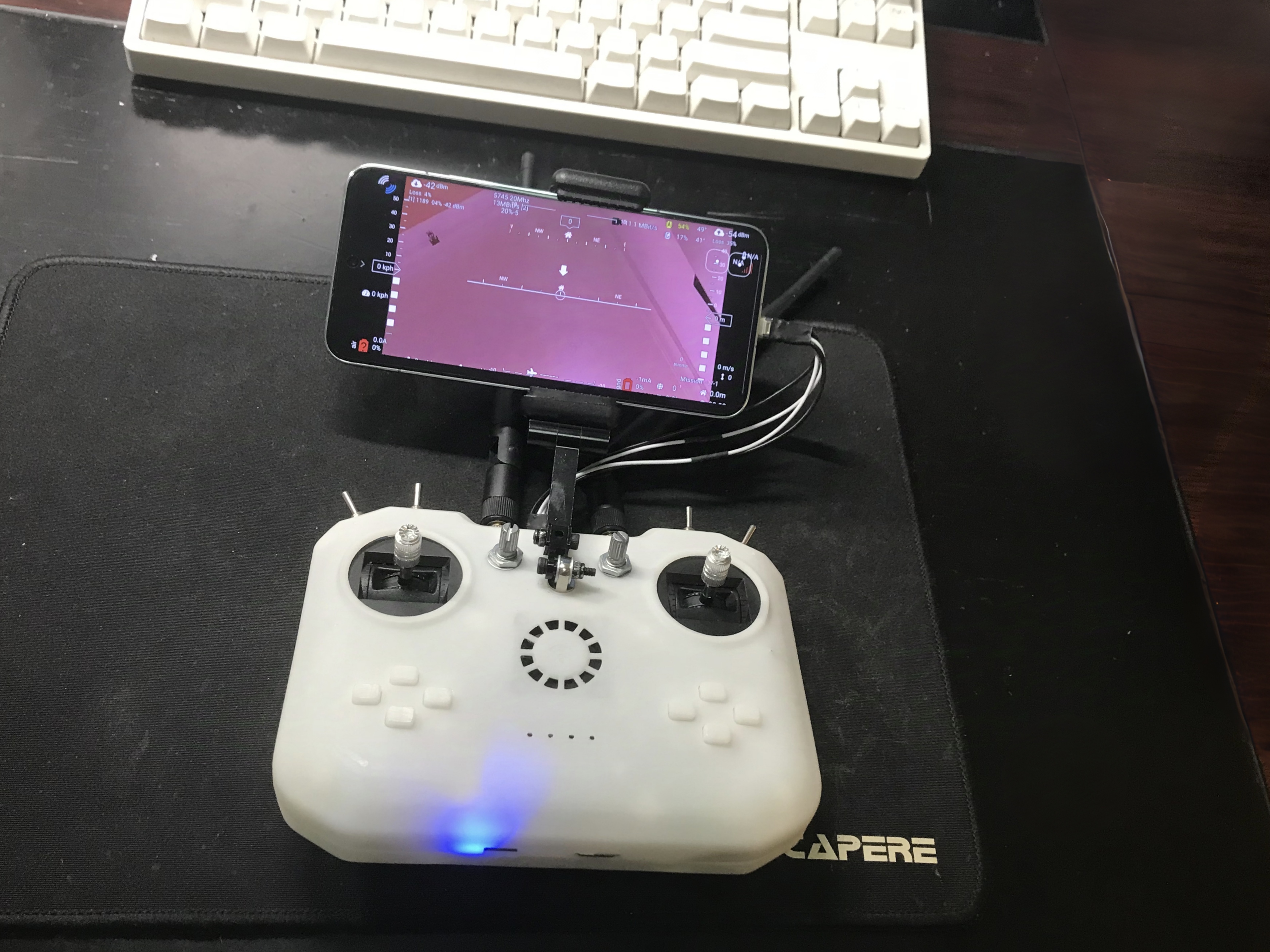
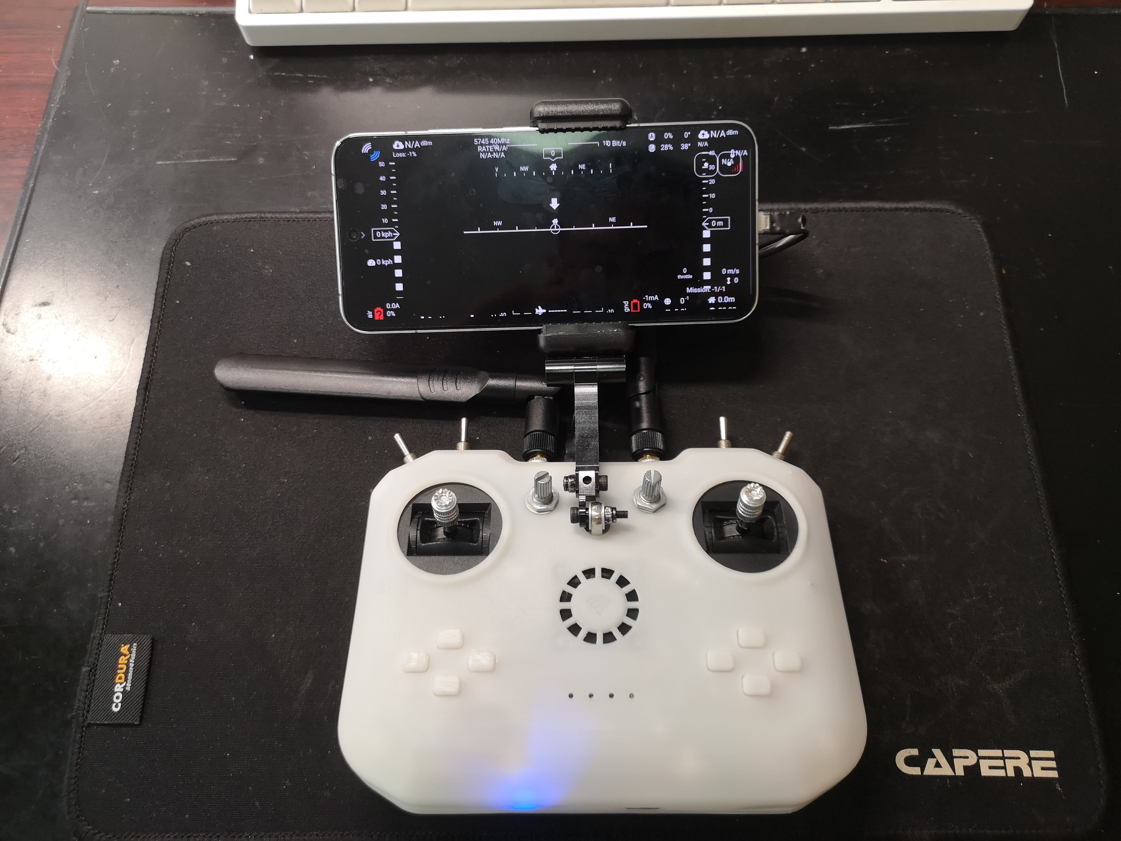
This project designs a remote controller with digital image transmission capabilities based on a Raspberry Pi. It only requires a single aerial unit and a camera to simultaneously transmit image data and receive remote control data, similar to DJI's remote controllers. This project is based on OpenHD, supports 16-channel data transmission, outputs an SBUS signal from the aerial unit, and displays the transmitted image on a mobile phone or HDMI screen on the ground unit. It also includes built-in charging management functions.
This project only includes the development of the ground unit remote controller; the aerial unit PCB in the project is only used for functional verification.
2. Open Source License CC BY-NC-SA 4.0 : Creative Commons License
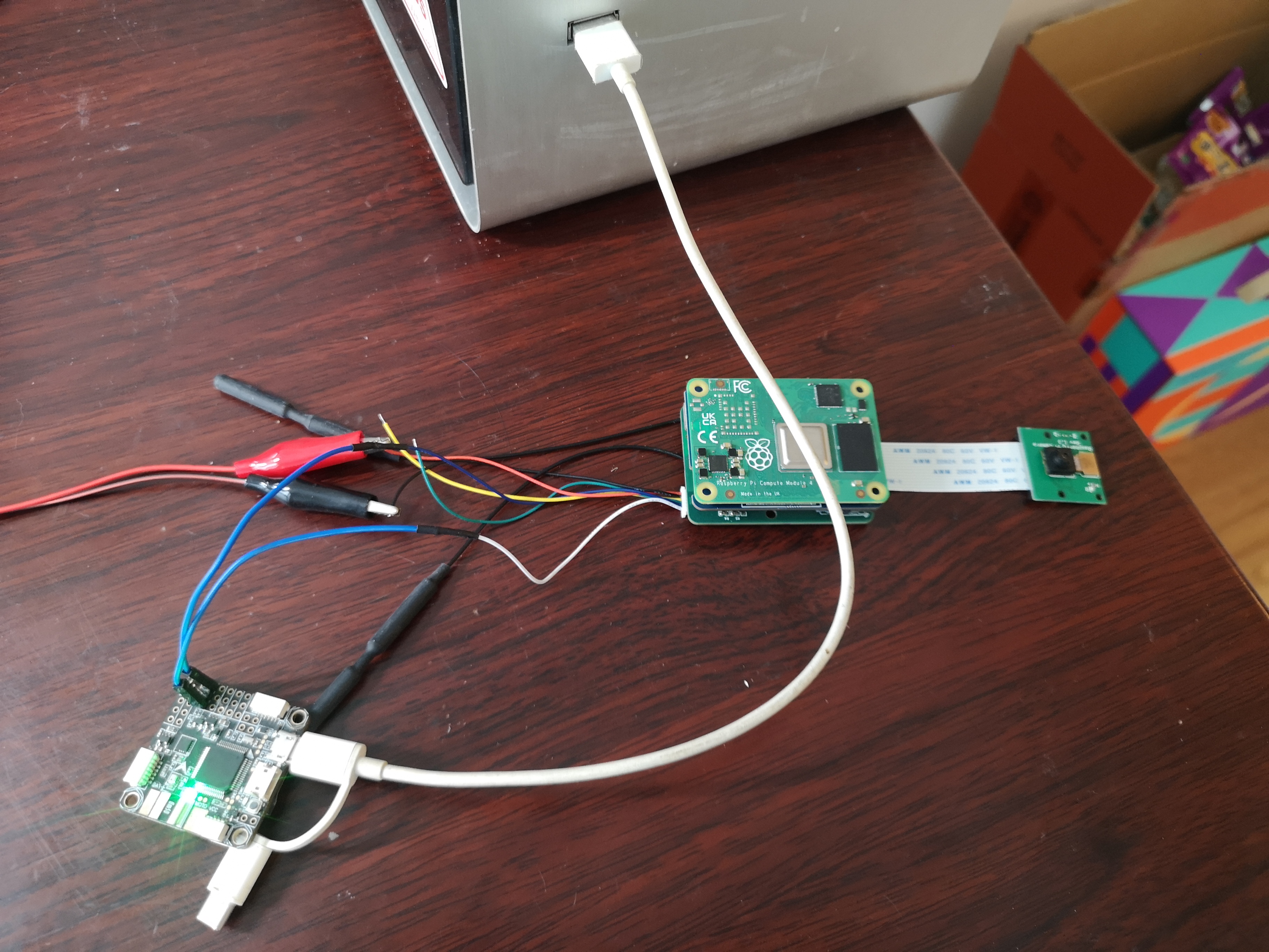
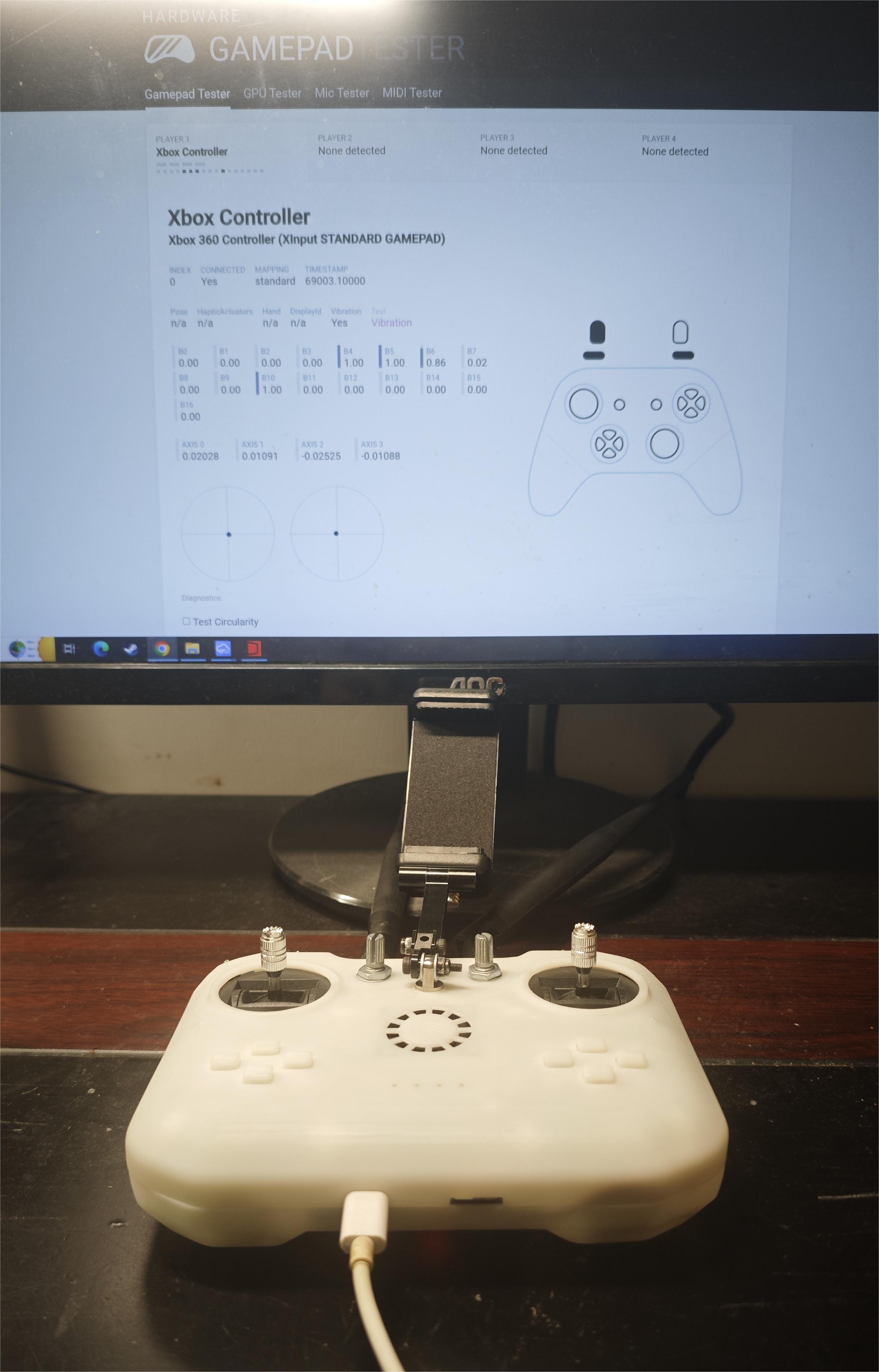
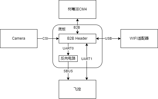
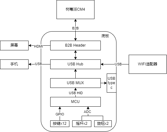
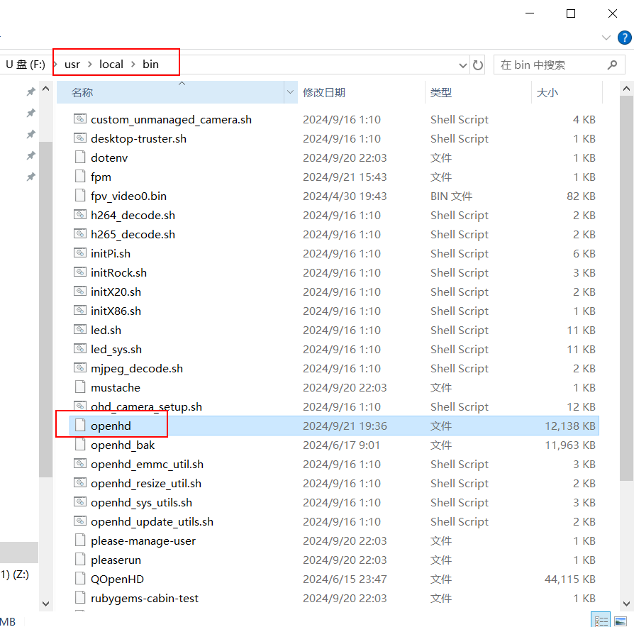
- Attribution-NonCommercial-ShareAlike CC: Abbreviation for Creative Commons license BY: Attribution, you must give appropriate credit, provide a link to this license, and indicate whether modifications were made (to the original work). SA: ShareAlike, if you remix, transform, or build upon this work, you must share your contributions under the same license as the original. NC: NonCommercial, you may not use this work for commercial purposes. 3. Project-Related Functions 3.1 Image Transmission: The aerial camera captures real-time images and transmits them to the ground-based remote controller via Wi-Fi. The remote controller supports USB connection to a mobile phone or HDMI connection to a screen for image display. The current camera transmission image specification is 720P@60. 3.2 Remote Control Data Transmission: The remote controller supports 6 analog channels and 10 switch channels. The aerial end supports receiving remote controller data and outputting it via the SBUS protocol. Here, the aerial end is connected to the SBUS interface of the flight controller, and then the remote control signal received by the flight controller is viewed on the computer using QGroundControl. 3.3 Controller Simulation: The remote controller supports USB connection to a computer and simulates an XBOX controller. 3.4 Charging Management: The remote controller has a built-in lithium battery charging management function, charging via connection to a computer or USB charger. 3.5 Other Features : The remote controller includes a mobile phone holder and a heat sink. 4. Project Attributes: This project is being publicly disclosed for the first time and is an original project by the author. This project has not won any awards in other competitions. 5. Project Progress: September 21, 2024: HDMI screen display, image transmission, mobile phone image display, computer and ground joystick recognition, sky-end receiving remote control data , SBUS data output, flight controller recognizing remote control data, power switch control , lithium battery charging, remote control data flow switching, 3D shell (first version) . 6. Design Principles : OpenHD currently offers the best support for Raspberry Pi. This project uses a Raspberry Pi CM4 for development. The following is a description of the sky and ground ends . 6.1 Sky End: The sky end completes camera data acquisition, WIFI data transmission, RC data reception, SBUS data encapsulation, and serial port data transmission. The hardware block diagram is shown below. 6.2 Ground End: The ground end completes image transmission signal reception, image decoding, joystick data acquisition, and WIFI data transmission. Because the OpenHD firmware only supports USB gamepads as input, the joystick and button data needs to be collected and transmitted to the Raspberry Pi via USB HID. An STM32 chip is used to complete data acquisition and gamepad simulation functions. The advantage of this is that the USB data can be output to the computer via the Type-C interface for data reception testing and emulator connection. The hardware block diagram is shown below. 6.2.1 The power supply design of this system requires a 5V power supply for the Raspberry Pi CM4, a 5V and a 3.3V power supply for the WiFi module, and a 3.3V power supply for the MCU. Additionally, the charging of the built-in lithium battery and the direction of USB HID data transmission when the USB is plugged in must be considered. The requirements are quite complex. To simplify the design, the automatic switching function between lithium battery charging and battery power is not implemented. Instead, a switch is used to switch between charging and power supply modes. The relationship between the switch and the USB is as follows: Switch on , Switch off, USB plugged in , image transmission runs, remote control data is sent to the Raspberry Pi; battery not charging , image transmission is off, remote control data is sent to the USB interface; battery charging, USB unplugged, image transmission runs, remote control data is sent to the Raspberry Pi; battery not charging , image transmission is off; remote control off, battery not charging. 6.2.2 Shell Design Reference Project: https://oshwhub.com/bukaiyuan/ESP32-hang-mu-yao-kong-qi 6.2.3 Interface Diagram 7 Software Description 7.1 Since OpenHD 's RC data is transmitted via serial port through MAVLINK, a flight controller supporting MAVLINK is required to receive the RC data. Therefore, for compatibility, a separate serial port is used to transmit RC data via the SBUS protocol. This requires modification of the OpenHD source code, which has been uploaded to my GitHub OpenHD repository: https://github.com/colourfate/OpenHD/tree/suppport_sbus 7.2 Ground Terminal 7.2.1 The OpenHD ground terminal does not require customization of OpenHD; the official OpenHD image can be directly flashed. 7.2.2 STM32 Firmware The ground terminal uses an STM32 chip to complete the joystick data acquisition and XBOX controller simulation functions. The following open-source project STM32 firmware is used directly: https://github.com/nesvera/STM32-X360-xinput/tree/master 7.3 Software Deployment 7.3.1 Flashing the OpenHD Image Download: Insert OpenHD ImageWriter into the TF card for flashing. Select Raspberry Pi evo-2.6.0 version. 7.3.2 Replace the OpenHD program in the Sky terminal by downloading and installing the ext4 file system driver. Insert the TF card, download the OpenHD program from the attachment, and replace the one in rootfs (it's best to back up the original one first). The path is /usr/local/bin. 7.3.3 Remote control firmware flashing for STM32.


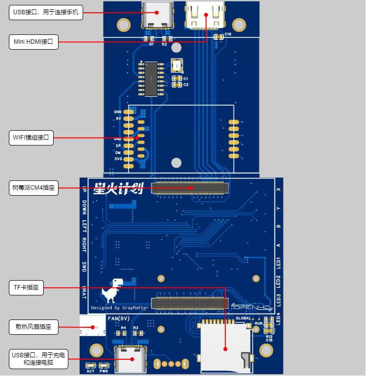


Download the STM32 firmware from the attachment and flash it via the onboard SWD interface. The SWD interface is on the back; refer to the interface diagram in 6.2.3. The pinout from top to bottom is VCC | CLK | DIO | GND
. 7.3.4 Install the QOpenHD APP on your phone.
Download QOpenHD .
8 Resource Summary
8.1 Material Recommendations
8.1.1 Ground Unit
Model
Quantity
Remarks
Core Board
Raspberry Pi CM4
1
CM4001000, without WIFI/EMMC, 1GB RAM
WIFI Module
RTL8812AU
1
Supports three modules:
1. A salvaged module, transmit power 150mW, requires flying wire soldering
2. Smart gateway hardware, transmit power 500mW
3. Bilian Electronics, transmit power 50mW
Charging Management Module
2S Charger
1
2S lithium battery charging module, refer to the link
Cooling Fan
-
1
Length 3CM/Width 3CM/Thickness 0.7CM, refer to the link
Joystick
-
2
small universal (centering) 5k with bearing, reference link; 2 5k 3-pin
rotary potentiometer
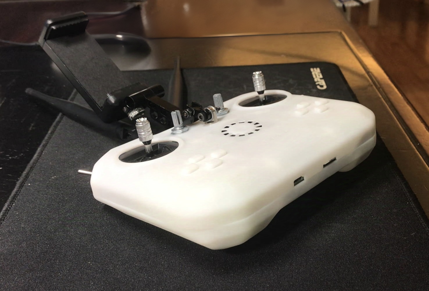
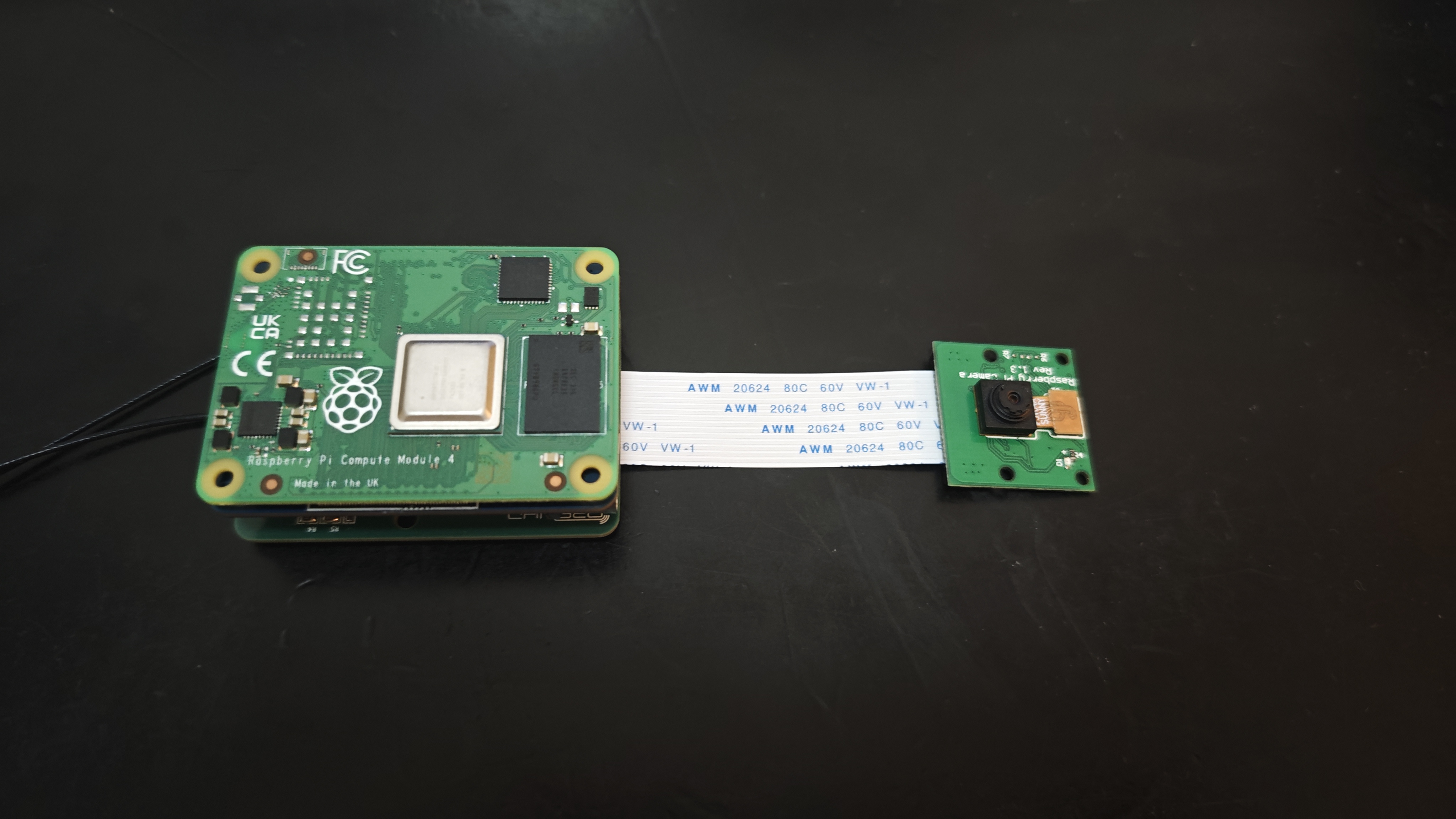
RK097NS , reference link; 4 3-pin 2-position toggle switch MTS-102 , reference link; 8 mute button , reference link ; 2 18650 lithium battery ( flat head recommended, with protection board) ; 1 USB Type-C USB 2.0 connector for making a double-ended USB cable to connect to a mobile phone (cannot use commercially available double-ended Type-C USB cables directly), reference link; this data cable looks okay , but hasn't been tested ; 2 5.8G WIFI antennas, reference link ; 1 universal phone screen bracket , reference link ; 1 M4 lifting screw (7mm long) for fixing the phone bracket , reference link; several M3/M2 screws for connecting joysticks, buttons, heat sinks, and countersunk nuts (M4 ), and several self-tightening nuts. 8.1.2 The overhead end has only been verified; the following materials are for reference only: Model, Quantity, Remarks; Core Board Raspberry Pi CM4, 1 CM4001000, without WIFI/EMMC, 1G memory WIFI module RTL8812AU 1 supports three modules: 1. A disassembled module, 150mW transmission power, requires flying wire soldering 2. Smart gateway hardware, 500mW transmission power 3. Bilian Electronics, 50mW transmission power Camera Raspberry Pi 1st generation 1 Reference link FFC flexible flat cable - 1 connects to the camera, 1mm pitch, 15P, same direction baseboard Microsnow Electronics 1 Raspberry Pi CM4 core board USB2.0/CSI interface expansion board Type A, reference link 8.2 Software Sky terminal OpenHD: Attachment 1 Remote control STM32 firmware: Attachment 2 8.3 Shell The first version has many problems, will be uploaded after improvement 9 Physical demonstration Bilibili video demonstration: https://www.bilibili.com/video/BV1Ju19YiEGk/?spm_id_from=333.999.0.0 10 Design considerations 10.1 The OpenHD official website describes the remote controller as follows: It's important to be aware that WiFi may not be ideal for transmitting many small RC packets. For the best experience, it's recommended to use a standard RC link operating on a different frequency than your OpenHD WiFi broadcast link. For example, you can use 2.4GHz ELRS for RC control and 5.8GHz for WiFi broadcast. In other words, WiFi is not an ideal communication link for transmitting small data packets like RC signals. For the best experience, it is recommended to use a standard RC remote controller on a different frequency band than WiFi. Therefore, this remote controller cannot replace a professional model aircraft remote controller. 10.2 Regarding the Sky Terminal : In this project, only the basic functions of the sky terminal have been verified, relying on a MicroSnow base plate. Considering the overall workload of the project, the sky terminal will likely be a separate project later. 10.3 Regarding Welding

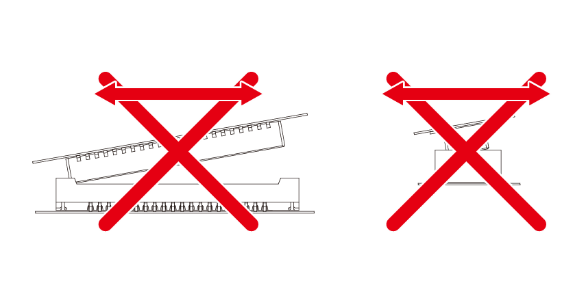
The Raspberry Pi CM4's two 100-pin connectors have a pin pitch of 0.4mm, and the module requires sufficient strength to insert and remove, making manual soldering very difficult. The recommended approach is to first tin all the pads, then align the connectors and place them on the connectors. Use a heated soldering iron for the first soldering attempt. Once the connectors are stable, use a very fine-tipped soldering iron to touch up the solder on each pin.
Also, when inserting or removing the connectors, apply parallel and even pressure; do not attempt to pull them out from one side.


 京公网安备 11010802033920号

 TCB150.01471%B


