**1. Function**
Use Liangshan School to realize intelligent car control, including but not limited to PWM speed control, obstacle avoidance and other functions.
The experience of the entire training camp is summarized in the attachment. For details, see the attachment: Liangshan School Intelligent Car Learning Notes, including but not limited to: programming specifications, schematic drawing, GPIO configuration, key lighting, PWM writing, serial communication, DMA receiving data, etc.
**2. Notes on schematic/PCB drawing**
1. At the bottom->Device->Search: Liangshan School, select Public, multiple Liangshan School 3D models will appear, select the main control chip facing up. Note: There is this public option in online mode, but not in semi-offline mode.
2. Diodes are directly searched in LiChuang Mall: SS34.
3. Motor drive selection: rz7899 or rz7889, the two pin packages are the same.
4. **Active buzzer, source means there is an oscillation source**.
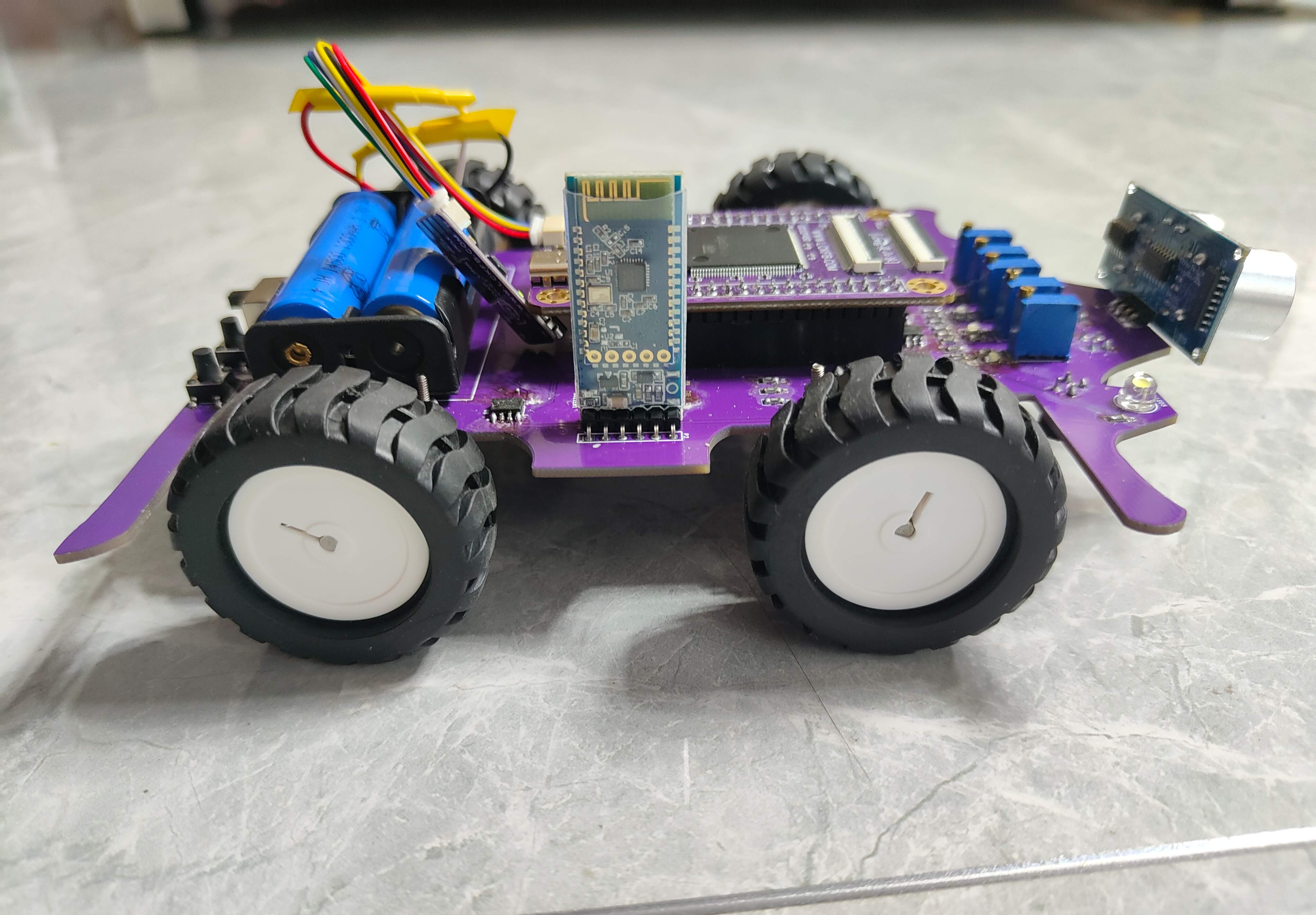
5. Notes on Bluetooth module, some of the VCC on this module is 3.3V, some are 5V, and some are compatible with both. Pay attention when purchasing. In addition, the RXD pin on the Bluetooth module is connected to the TXD on the microcontroller, and the TXD pin on the Bluetooth module is connected to the RXD on the microcontroller. When drawing the Bluetooth module pins, remember to swap RXD and TXD (so that they can be correctly connected to the main control chip).
6. For infrared tracking, choose: ITR9909.
7. Comparator: LM393.
8. After the schematic diagram is drawn, you can use a rectangular frame to divide the functions to make the entire schematic diagram more organized. You can also add functional descriptions to the schematic diagram.
9. ** Liangshan School model selection, the main control faces people, and the pins are on the back. ** Pay attention to the direction of the pins when welding.
10. ** When laying out the PCB, you must pay attention to the position of the motor, and you must adjust the motor offset to align it with the holes on the board frame. **
11. ** Alignment, it is best to use shearing and select the reference point, which is fast and accurate. **
12. ** shift+P, regional placement function. **
13. The four pins of the motor driver chip should be placed on the bottom layer.
14. The power signal line can be set to 40mil, and the motor signal line can be set to 80mil.
15. ** The vias of the power signal line can be modified in size, with an inner diameter of 24 and an outer diameter of 48. **
16. The rated voltage of the buzzer here is 5V, which is related to the device model. Select the voltage according to the manual.
17. When debugging, I found that the control pins of the four wheels were inconsistent with those in the teaching video. I need to debug them one by one to confirm the corresponding pins for each wheel to move forward and backward.
18. The placement position of the Bluetooth module in the schematic diagram can be rotated 180°, otherwise the buzzer will be squeezed during the actual welding process. The schematic diagram needs to refer to the physical pins of the hardware.
19. First use the motor IO program to test the rotation direction of each wheel. If the rotation direction is opposite to the control signal, you can swap the two pins of the motor (flip the motor 180° and then weld) or change the code (swap the forward and backward function codes).
**III. Summary**
1. First, you have to learn how to use Liangshan School. You can refer to the previous 20-day Liangshan School learning course, and attach the learning notes of the 100 lectures of LiChuang Professional Edition.
2. It is very time-consuming to wire while watching the video. After you are familiar with it, you can watch the video first and then wire it yourself.
**IV. Demonstration video**
1. Turn on the lights
2. Motor control
3. Ultrasonic obstacle avoidance, it will stop and then move back when encountering obstacles
4. Bluetooth remote control, attach the remote control APP interface and the small program APP (only one mobile phone can't shoot the content of the remote control car).
5. The car source code, with annotations, easy to understand, has been debugged.


 京公网安备 11010802033920号

 303134-69R8-B-B-W


