PCIe to Quad-Bay U.2 (SFF-8639) Backplane (eDP Version)
Version History:
v1.1 2024-09-29: Added chassis and bracket information
v1.0 2024-09-14: Tested and working properly
v0.1 2024-06-29: Initial Design
Introduction
A year ago, I designed a PCIe to quad-bay U.2 backplane using FI-R 51p connectors. During long-term use, I noticed that the backplane occasionally experienced hard drive speed reduction or failure to recognize the hard drives. The FI-R connectors were too thick and wide, which was not conducive to component layout and enclosure design (for example, if placed on the same side as the U.2 interface, it might hit the hard drive enclosure when connecting a hard drive). Furthermore, JLCPCB removed the restriction that free prototyping of six-layer boards required BGA components during the year, so I decided to reset and upgrade this project.
Compared to previous projects, this project has the following major changes:
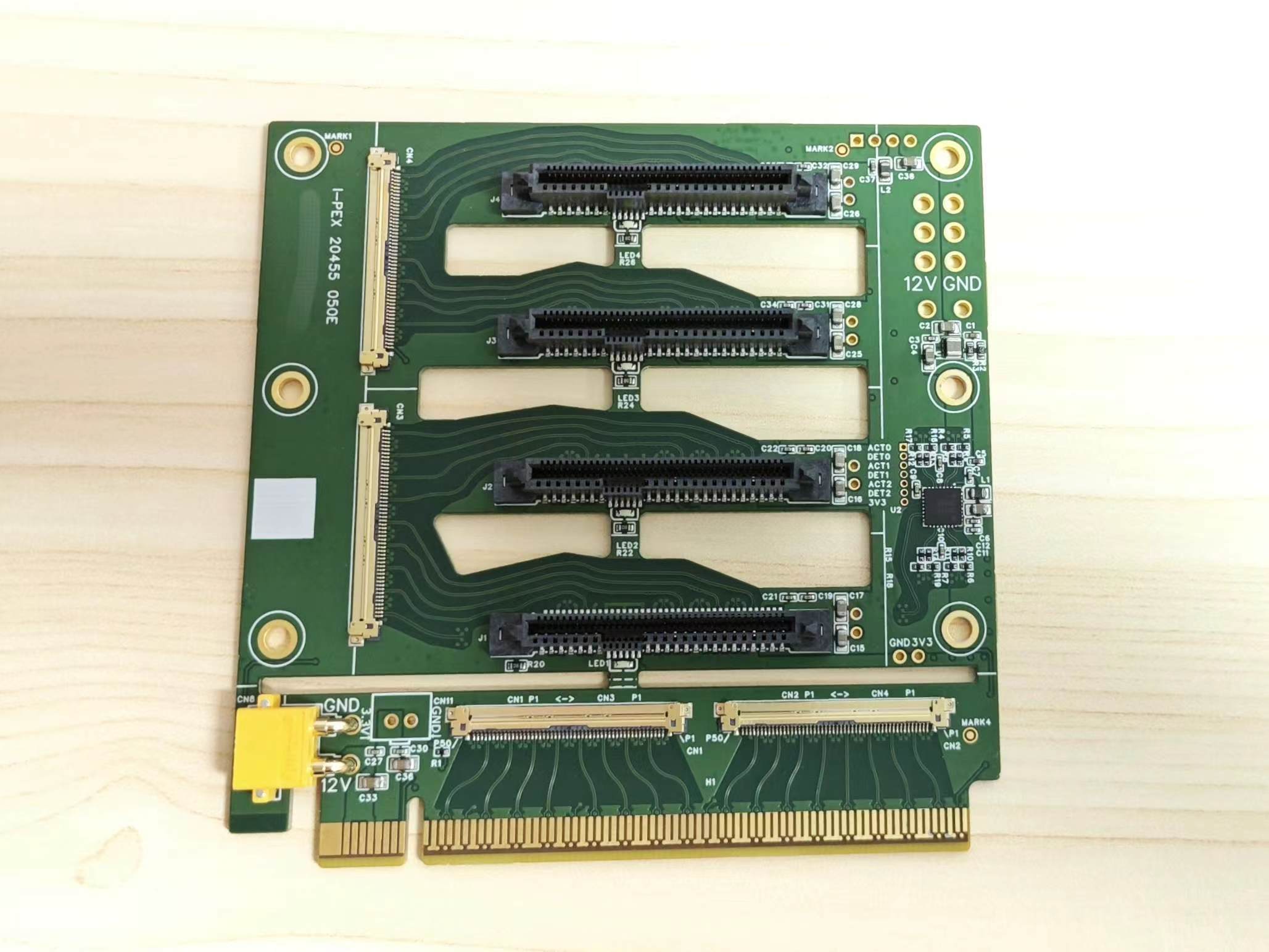
the connector has been replaced with I-PEX 20455 050E, and the matching cable is I-PEX 20453 50P non-circular/reverse cable, which significantly reduces the size and is commonly used for eDP screen cables;
the impedance design is tailored to JLCPCB's six-layer 3313 stacked structure, with a PCIe data line differential impedance of 85 Ω and a clock line differential impedance of 100 Ω, and more impedance control designs have been added;
most surface-mount components are placed on the top surface (except for the 0 Ω resistor for LED configuration, detailed later), allowing the use of JLCPCB's economical surface-mount components, eliminating the need for manual soldering of U.2 female connectors;
two mounting holes have been added and their positions adjusted, no longer compatible with 2080 aluminum profiles :(, but a matching housing and a bracket adapted to a certain NAS chassis are available :) (still under design);
support for fan "daisy chain" has been removed, retaining only a 4-pin connector connecting 12V and GND. Pin header location. This project
is designed
for JLCPCB's six-layer 3313 stack-up (JLC06161H-3313), with a board thickness of approximately 1.6cm, copper thickness of 1/0.5oz, and PCB dimensions within 10cm x 10cm. The minimum via inner diameter is 0.3mm. The minimum component size is 0402, the shortest pad center distance is 0.5mm, and most surface-mount components are located on the top surface, with 5mm space on the top and bottom sides for no surface-mount components. There are four surface-mount identification marks on the top surface. JLCPCB six-layer immersion gold prototyping vouchers and economical surface-mount components can be used (the "gold finger bevel" process should not be selected, otherwise it will be considered a special process, and only standard surface-mount components can be selected).
The U.2 female connector package is designed based on Foxconn LU25683 and may be compatible with other harpoon pin mounting models. For machine mounting, it is recommended to purchase the model with the suffix 9H (LU25683-A001-9H), which comes in tape and reel packaging with a top cover. Models with the suffix 4H come in tray packaging without a top cover.
Using
this backplane requires a motherboard that supports PCIe splitting; ideally, the x16 slot should be split into 4+4+4+4. If it can only be split into 8+4+4, the system may not be able to recognize one or more hard drives on the U.2 interface.
Cut along the thin slot above CN1-2 and connect CN1-CN3 and CN2-CN4 using an I-PEX 20453 anti-planar/reverse ultra-thin coaxial cable. This cable is available on Taobao; a 300mm length cable costs no more than 25 RMB.
The PCIe daughterboard has a pad for an XT30 PW-M female connector, which allows you to draw 12V from the PCIe slot and connect it to the XT30 UPB-M female connector on the backplane to power the hard drive. However, according to the PCIe specification, the slot can only provide a maximum of 75W of power, while a U.2 drive typically consumes up to 25W under full load. Therefore, it is not recommended to connect multiple high-power hard drives to the backplane when drawing power from the slot. For common ATX power supplies, it is recommended to use a PCIe 6-pin connector to power the backplane. The 3.3V power supply can be provided using the onboard step-down module (U1) or an external power supply (CN10, 2.54 pin pitch).
It is recommended to check for short circuits, signal continuity, and voltage before connecting the hard drive and powering on to avoid situations where the power supply is excessively high. Compared to the previous version, this
design incorporates more impedance optimization measures, such as:
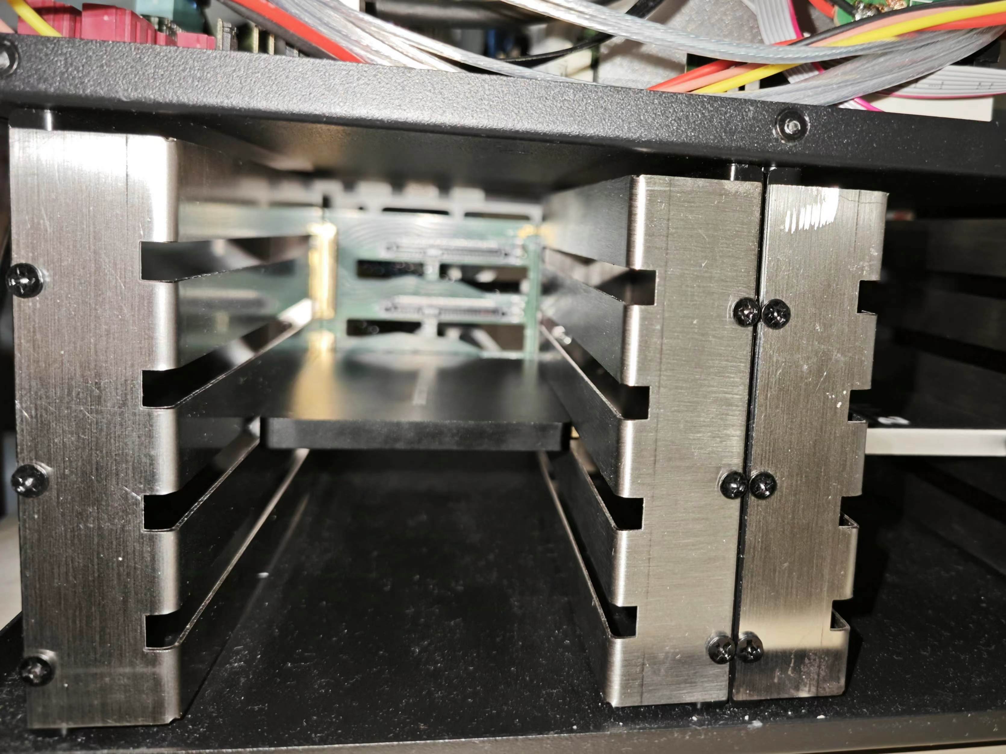
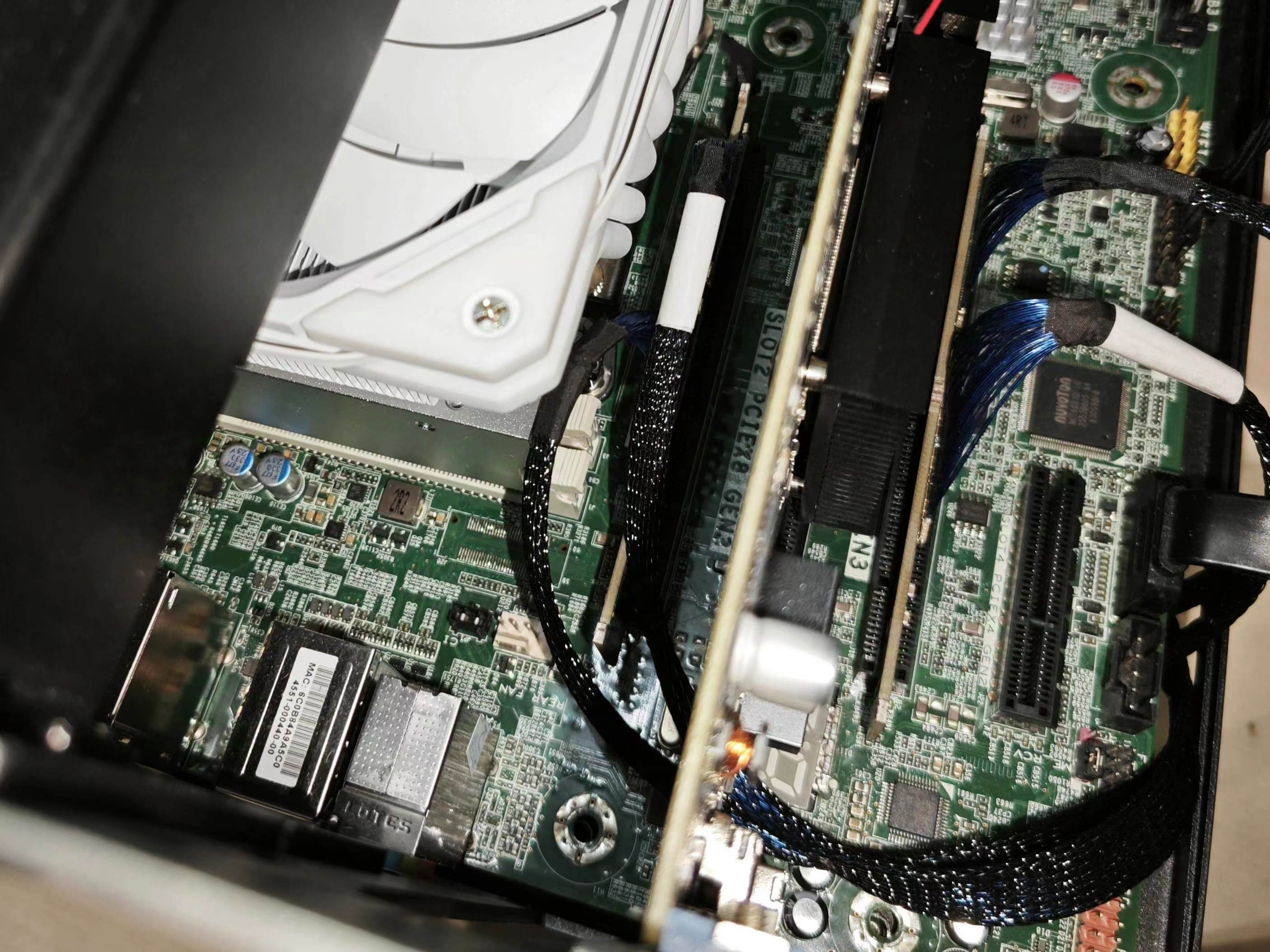
removing a layer of copper beneath the pads for cross-layer reference; ensuring no trace splits near the reference ground plane of all differential lines and no silkscreen covering on data lines; removing unused pads on vias and adding anti-pads; increasing the spacing between differential lines and copper on the same layer, and removing residual ground copper between differential lines; and reducing the amplitude of serpentine lines when adjusting for equal lengths. However, due to the layout changes, some negative factors affecting impedance have been introduced: half of the data lines and all hard drive clock lines pass through two vias (top-bottom/inner layer-top), and the input reference clock passes through three vias; the clock buffer chip is poorly positioned, resulting in long clock traces; ideally, the clock buffer should be placed in the middle of the left side of the board, close to the I-PEX connector (CN 1-4) and the clock pins of U.2, but its peripheral components occupy a large area and are prone to conflict with connectors and mounting holes. Any optimization suggestions from experts are welcome. The 12V main power supply retains both PCIe 6-pin (CN7) and XT30 (CN8-9) connection options. Due to the clock buffer placement and enlarged heat dissipation openings, the 12V copper pour width is slightly reduced compared to the previous version, but it should still be sufficient for the 25W requirement per drive. The surface-mount solid capacitors placed on the board edge in the original design have been removed, replaced by through-hole pads (C13-14, C23-24) next to each U.2 female connector, allowing for capacitors to be added from the back. The 3.3V power supply buck module has been replaced from NAE12S03 to TPS82130 (U1), slightly reducing costs. Similarly, 2.54mm pitch through-hole pads (CN10, CN11) are provided on the board for connecting to 3.3V and GND, allowing for the option of soldering pins instead of mounting the buck module for external power supply. Alternatively , a step-down module can be installed, with 3.3V output taken from the connector pins. However, it is not recommended to install both the step-down module and take 3.3V input from the connector pins, as this may damage the module. In addition to removing the fan "daisy-chain" function mentioned above, the design of directly mounting an 8cm fan on the board has also been removed. This design significantly interfered with the board layout, such as preventing wiring at the openings and limiting the placement of through-hole or even tall surface-mount components within the fan's corresponding area. This version retains only one 4-pin fan connector (CN5), and the speed measurement and control wires are unused; these functions can be manually wired if needed. The fan may be moved to the casing for mounting in the future. Furthermore, compared to the previous version, this version has a larger ventilation slot area. The chassis and bracket : This backplate can be used with an adapter bracket to modify the Aurigas NAS chassis (aluminum version), which originally supported 6 x 3.5" hard drives, to support 8 x 2.5" U.2 hard drives. The bracket model file is attached. The hard drive bay structure of the Sky Arrow chassis is said to be the same as that of the Aurigato chassis, but it has not been tested whether this bracket is compatible with either the Sky Arrow or the Steel Aurigato chassis. The installation result is shown in the picture:
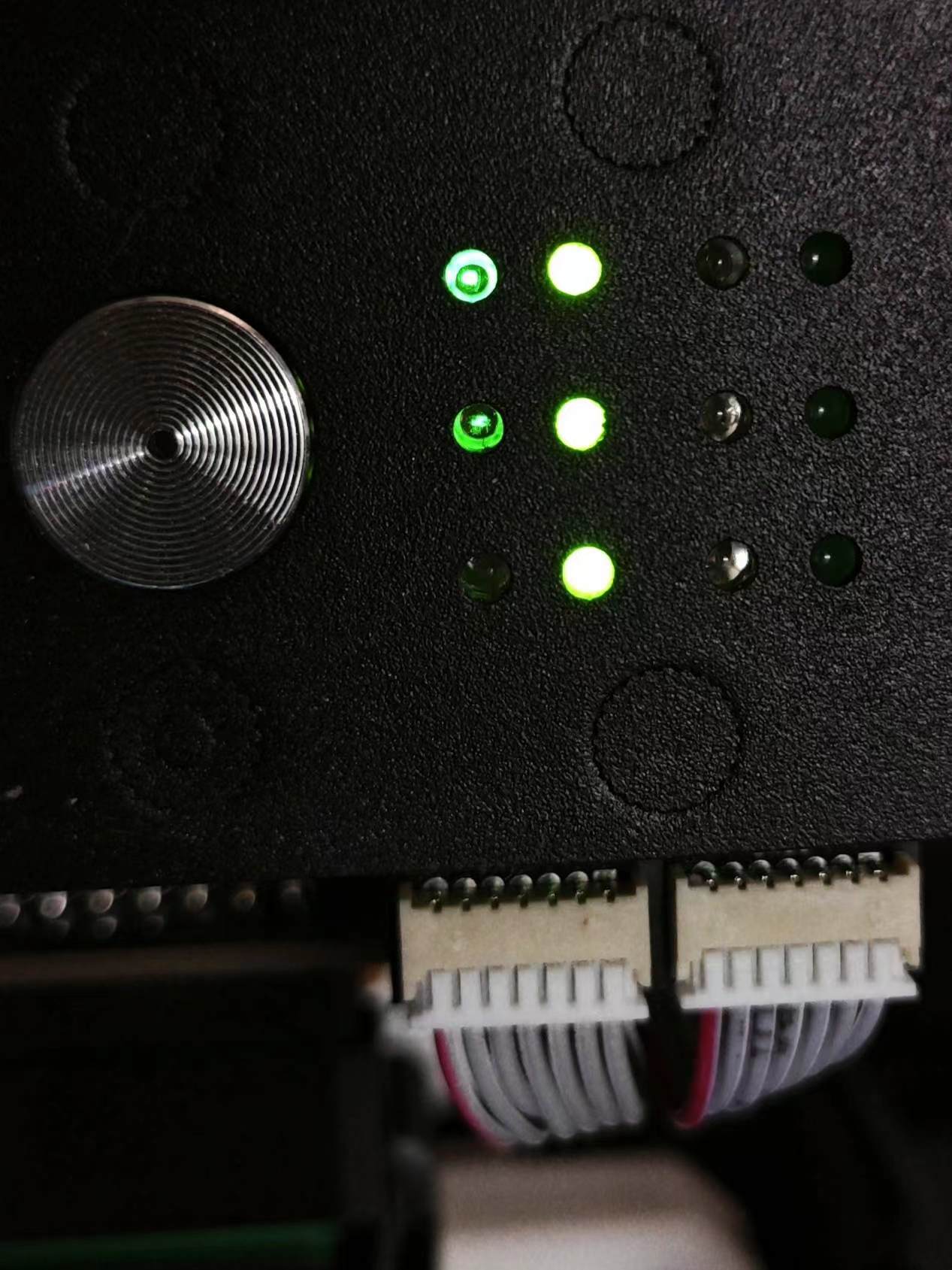
SSD slots 1-3 can be indicated by the presence/activity indicator lights on the front of the chassis (since there are only three sets of indicator lights on the chassis, the bottom SSD0 is not supported):
The bracket and backplate installation steps are as follows. Due to the small size margin of the bracket, it is recommended not to tighten the screws securing the bracket and backplate all at once. After installing the hard drive and making minor adjustments to its position, tighten them completely. However, the hex studs should be directly secured in place:
Remove the original hard drive cage and backplate, and run the power and indicator light cables to the hard drive bay;
Install M3 threaded, 5mm high hex studs on the bracket and secure them with nuts;
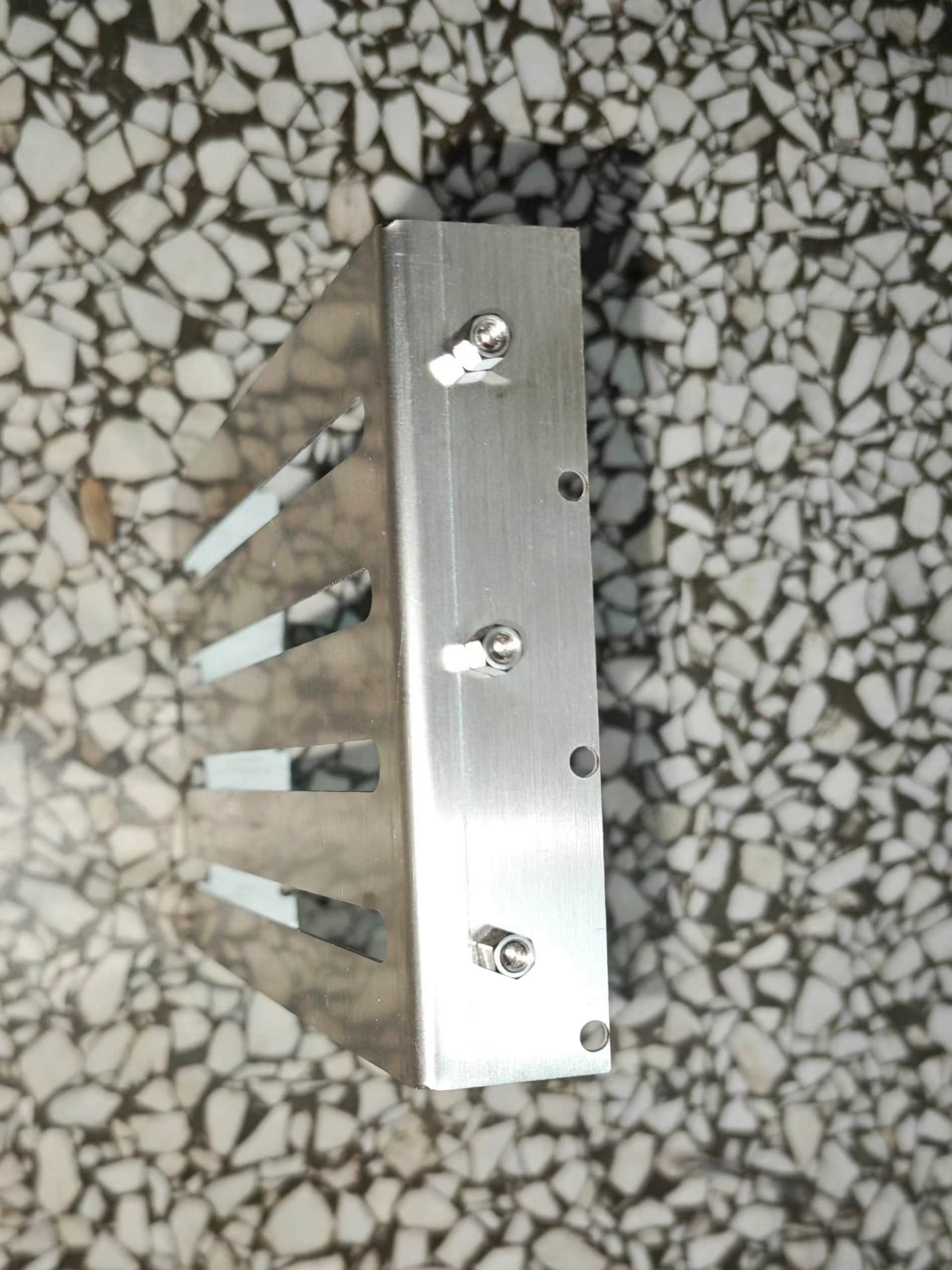
Insert the bracket diagonally into the hard drive bay from the front, then rotate it to vertical position, and use the original hard drive cage and backplate screws to secure the bracket to the hard drive bay;
Connect the coaxial cable to the backplate, insert it into the hard drive bay, and then use M3 threaded, 4mm high hex studs to secure it. Secure the backplate to the bracket studs using round-headed screws (screw head diameter should not exceed 6mm). Ensure the coaxial cable passes precisely through the gap between the two studs and between the backplate and bracket.
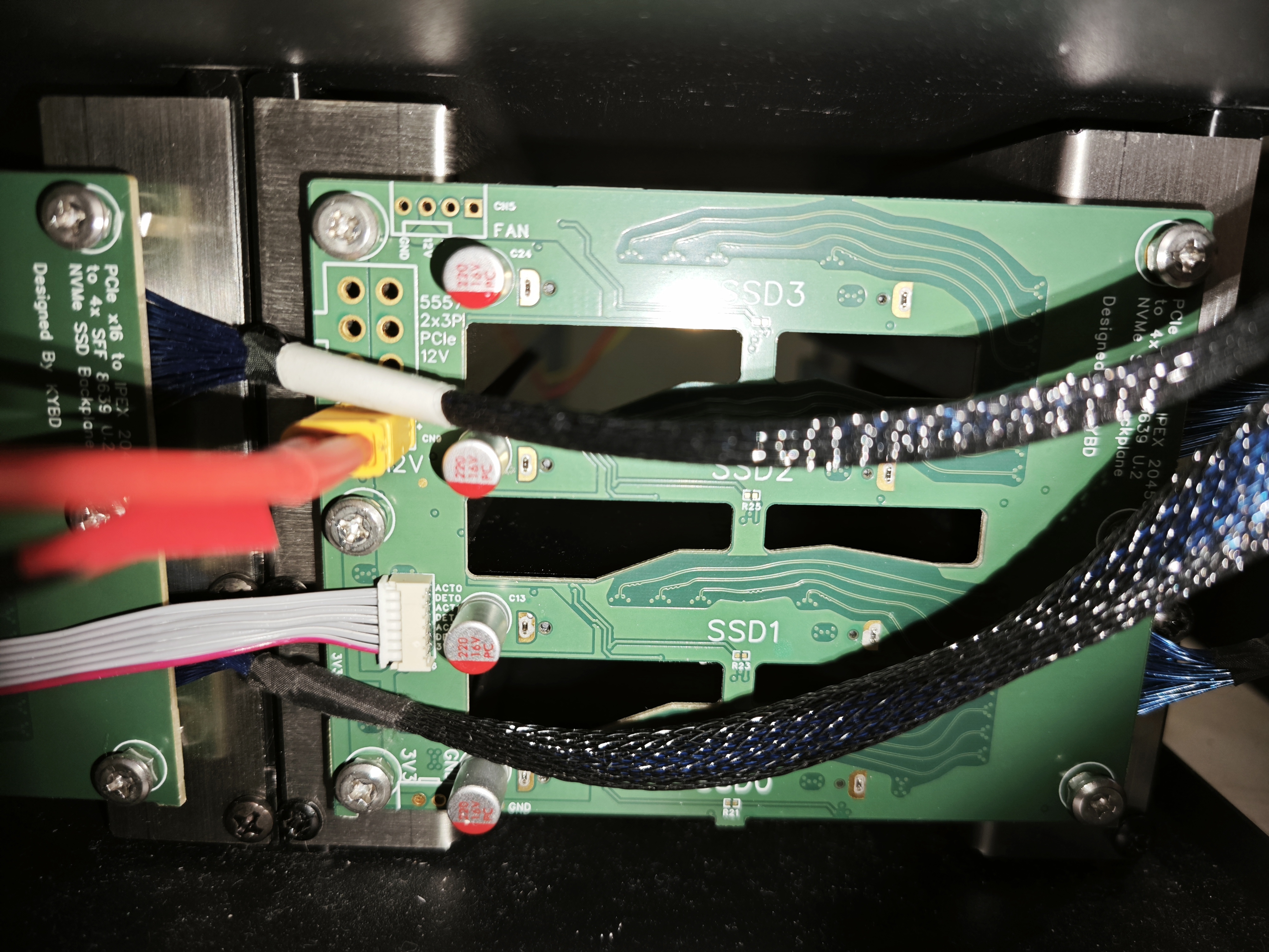
Connect the power and indicator light cables.
Thread the coaxial cable through the motherboard bay, connect it to the PCIe daughterboard, and install it into the motherboard slot. Note the connection order: the lower coaxial cable on the backplate should connect to the daughterboard closest to the PCIe bracket. A 300mm long coaxial cable is sufficient to install the daughterboard corresponding to the backplate near the CPU into the third slot of the motherboard, or the daughterboard corresponding to the backplate near the PCIe slot into the first slot.

Install the hard drive. Use the aforementioned M3 threaded, 5mm high hexagonal studs, or M3 screws and nuts or washers with a diameter not exceeding 6mm, in the hard drive mounting screw holes. Then slide the hard drive into the bracket slot and connect it to the backplate.
Use tape or other tools to seal any gaps to control airflow and ensure effective heat dissipation. To accommodate the hard drive presence/activity indicator
lights
on the aluminum version of the Gouriza chassis, this version includes a 7-pin connector pad (CN6) on the right side for connecting the ACT and IFDET pins of SSDs 1-3. To avoid conflicts, 0Ω resistors (R21, 23, 25, 27) are placed on the back of the chassis between the onboard activity indicator lights (LED1-4) and their corresponding ACT pins. If you don't need to use them on this chassis and still want to see the onboard activity indicator lights, you can connect these resistor pads together with a lump of solder.
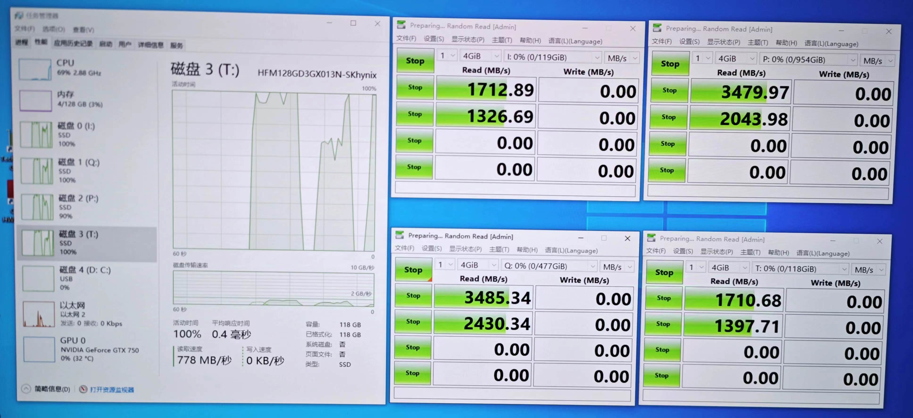
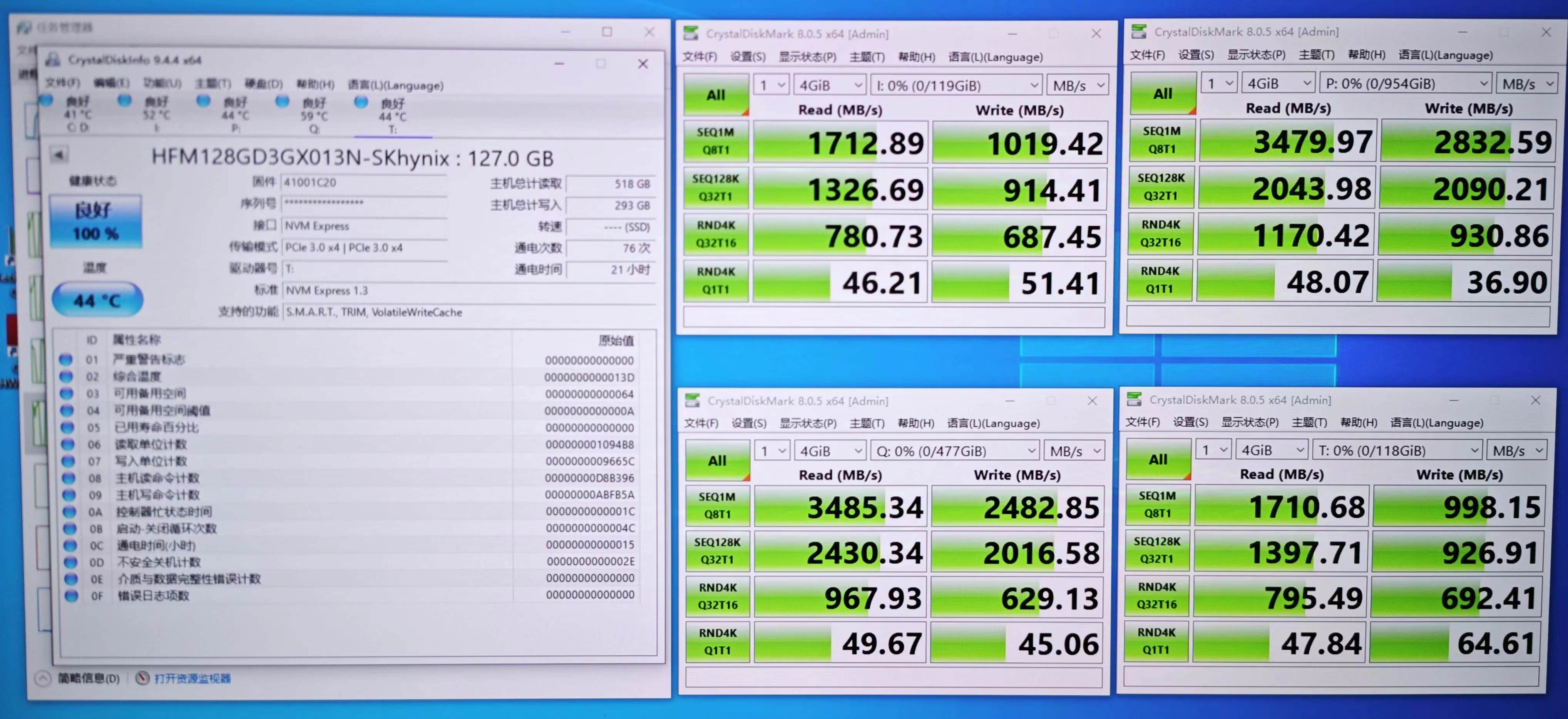
The test
used four M.2 hard drives connected to the U.2 interface and tested on an E5 v4 machine. The motherboard was configured with x4/x4/x4/x4 slots. All four hard drives were recognized and successfully negotiated to PCIe 3.0 x4, reaching the drive's rated read/write speed.
(Image
v1.0 version:

Known issues
v1.1)
The signal fan-out routing of the 20455 connector on the backplane can be adjusted to create more space for heat dissipation slots;
the clock routing of the SSD section can be optimized, reducing its length and minimizing its impact on auxiliary signal routing;
the position of the 8639 connector needs minor adjustment to reduce interference between the hard drive and the side brackets;
the solder mask on the 12V and GND sections should be opened to enhance current carrying capacity;
the solder mask on the back of the clock buffer and buck module should also be opened to enhance heat dissipation;
the 12V connector on the PCIe daughterboard should be replaced with an XT30PW-F. The fixed feet occupy less space and allow for more flexible layout;
there is an error in the silkscreen markings near the indicator light cables on the back panel; the following designs and documents were referenced
during
the design of this project, and I would like to express my gratitude to the authors:
PEX8796_PCIE_GEN3_24PORT_Switch - OldMonster;
Inspur 2.5-inch rear hard drive cage modified to NVMe back panel - OldMonster, the design files are in their group;
PCIe_Bifurcation - OldMonster;
AN 672: Transceiver Link Design Guidelines for High-Gbps Data Rate Transmission - Intel
PCIe to four-bay U.2 back panel using FI-R 51p connector - kybd


 京公网安备 11010802033920号

 GBS-9280F-C390G


