This RGB intelligent fan-driven laptop cooler, based on the ESP Wroom 32e, consists of a main control PCB (communication module, main control module, power supply module), button PCB (button switches, knobs), RGB light strip, turbine fan, and a 3D printed shell.
Background: The heat dissipation and noise control performance of thin and light gaming laptops is generally average, so I decided to make a fan-driven laptop cooler to improve this problem and at the same time beautify my desktop. Functions: Air pressure cooling, RGB equivalent, button and knob control, software remote control, voice assistant intelligent control.
Demonstration: https://www.bilibili.com/video/BV1nitfehE3X/?vd_source=d1f3fc84c98ce29f0b067a18ea300d05
Major Components List:
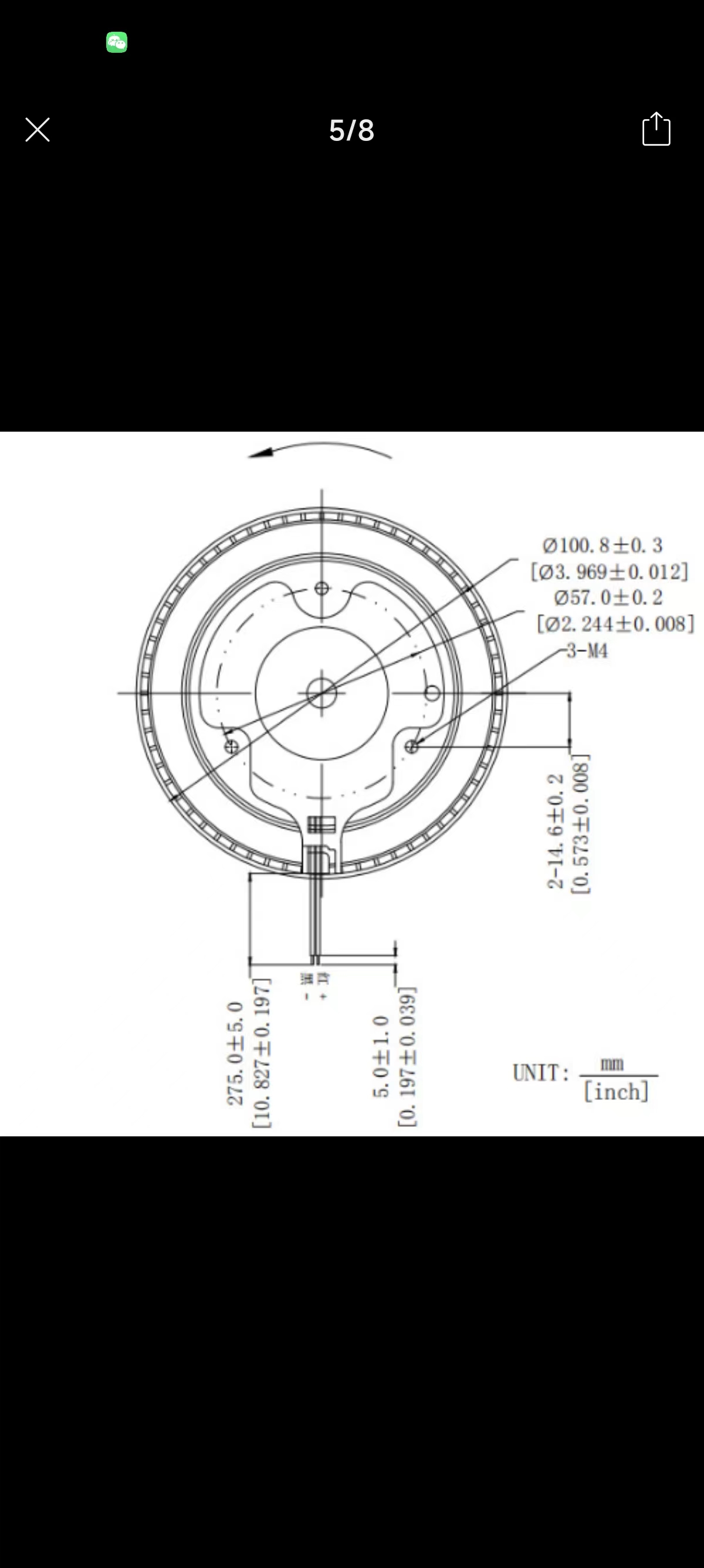
1. Two 12cm turbine fans (
purchased from Pinduoduo; the seller no longer sells them, but they're basically the same; theoretically, turbine fans with screw hole specifications as follows (diameter less than 12cm) can be used).
2. WS2812 LED strip (purchased from Pinduoduo; LED density doesn't need to be too high, 60-80 LEDs/meter is fine; buy one meter)
. 3. Soft sponge single-sided tape, 2cm wide, 1cm thick.
4. 502 glue, hot melt glue, light-shielding tape.
5. DC power supply (12V). 2A or 3A (1A not recommended), DC power female connector
model:
I used Tuozhu X1C for
3D printing. Printing consumables: ESU's economical white PLA. All models in this project will use approximately 700g.
When slicing the model, the two largest printable parts (left and right main body) were adjusted to 6 layers for the walls, and the RGB light strip walls were adjusted to 4 layers with an infill density of 8%. Adjusting the number of layers is mainly to suppress light leakage. My RGB light strips use a honeycomb infill method; different infill methods will result in different light strip effects (different patterns). It
is recommended to use light-shielding tape to fix the RGB light strips. Also, apply an appropriate width of tape above the light strips (to suppress light leakage).
See the attached SW file for the
code:
For simplicity, ESP32 and Arduino software are used. The IDE
communication module code (XT.ino) involves adding the network access configuration from DianDeng Technology. For specific methods, please refer to the DianDeng Technology tutorial (i.e., obtaining the key, filling in the key, WiFi, WiFi password).
The value of "NUMPIXELS" in the main control module code (ZK.ino) should be adjusted according to the actual RGB LED strip used.
The code file is attached.
PCB:
See the schematic and PCB at the end of the project.
A picture of the soldered result is also attached.

Assembly tips:
Before assembly, please complete other tasks, such as ensuring
high voltage is required in the area where the fan is located during code burning. The gaps in this enclosure are... This was my first time making buttons using 502 glue

. The inside was just a jumbled mess. The blue strip is an RGB LED strip (facing down, on both sides, with wires soldered in the middle) (you can keep the printed support and use it as filler on the LED strip). The folded filler is paper and heat shrink tubing, and the clump is hot melt glue. I was too lazy to buy a new 5-pin XH2.54 cable, so I just used DuPont wire and heat shrink tubing. Some people suggest using XH2.54 wire.

The clump is hot melt glue. Refer to the PCB file for the connector order.
Note: the positive and negative terminals of the XT connector are reversed here. Please pay attention when wiring. Refer to the following diagram (red line is positive).
Extend the XT cable to the right rear of the casing and connect it to the DC female connector. The DC female connector can be directly inserted into the model.

Finally, put on the cover and apply soft sponge and single-sided tape (the effect depends on your dexterity). That's it! (If the laptop is not wide enough to allow air to pass through, you can do the following: add a little sponge on both sides and stick it slightly inside the casing.)
Laptop Cooler Model.zip
TX.ino
ZK.ino
PDF_RGB Intelligent Air Pressure Laptop Cooler.zip
Altium_RGB Intelligent Airflow Laptop Cooler.zip
PADS_RGB Intelligent Air Pressure Laptop Cooler.zip
BOM_RGB Intelligent Air Pressure Laptop Cooler.xlsx
90776
Three-channel square wave generator circuit
This is a three-channel square wave generator based on STM32 that can generate an adjustable frequency from 1Hz to 8MHz.
The preface
was a template provided by JLCPCB, which I filled in directly. Therefore, please don't blame me for any repetitive descriptions or logical errors in the following text. (Disclaimer)
Video Link:
I'm too lazy to upload it to Bilibili, so just check the attachment below.
Project Introduction:
This is a three-channel square wave generator based on STM32 that can generate an adjustable frequency from 1Hz to 8MHz.
(Actually, it's a problem from the 2024 Yanshan University Electronic Engineering Competition Autumn Round. I just finished it and uploaded it; the hardware and code are terrible.)
Project Function:
This design is a PWM generator based on an STM32 microcontroller; it has three separate PWM outputs: a screen and a button panel.
Function: Based on the frequency required by the button output, the output will be automatically activated, and the corresponding PWM will be output automatically.
Project Parameters:
The overall hardware design of the project is not difficult, but the choice of the main control chip was very difficult. High-frequency chips are expensive; cheap chips have low frequencies.
Ultimately, an extremely cheap chip was chosen. If you want to achieve a smaller error in the high-frequency range, you'll have to pay extra!
This design uses the STM32G030F6P6 main control chip, which is small, inexpensive, and has all pins arranged appropriately for the needs. The design uses a 0.96-inch OLED display
with three rows corresponding to three outputs.
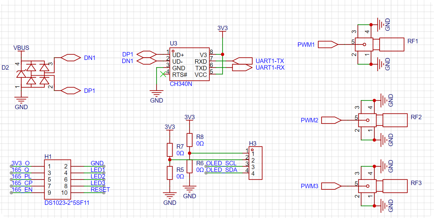
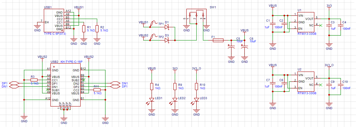
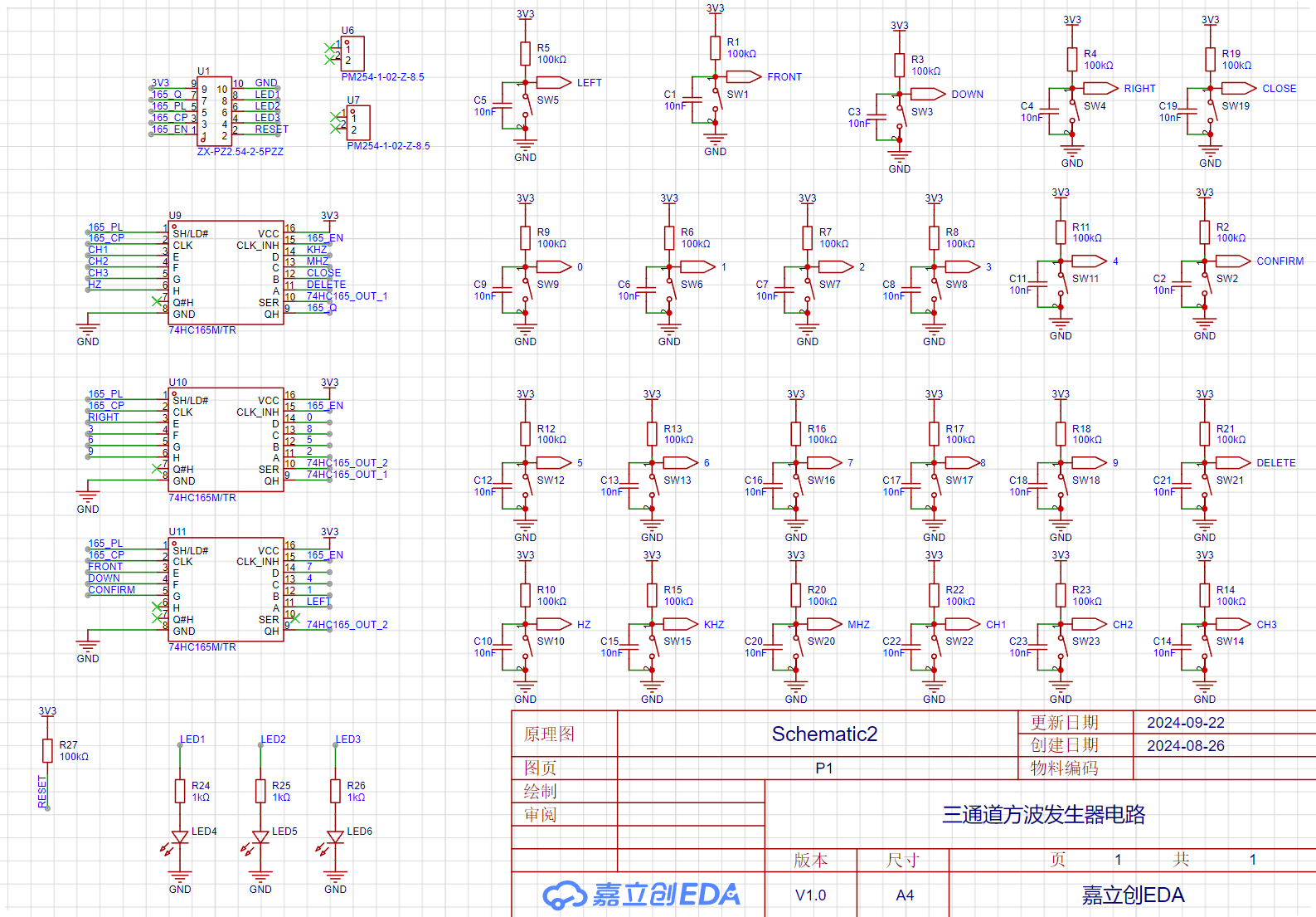
Software calculations are used to obtain the optimal solution for the timer divider and counter while keeping the system clock constant. The project consists of two circuit boards and a purchased 0.96-inch OLED. You can find the 0.96-inch OLED on Taobao (click the blue text to jump). The main control board consists of three parts: the core, peripherals, and power supply. The core part essentially involves the minimum system and pin layout of the STM32G030F6P6. Regarding the pin layout, the peripheral pins are as follows: | Function | Number of Pins | Corresponding Peripheral | Role | | --- | --- |---|---| | Chip Programming Interface | 2 | SWDIO | Programming | | Chip Reset Pin | 1 | NRST | Program Reset | | RF Coaxial Connector | 3 | PWM | Three-channel PWM Output | | 0.96-inch OLED | 2 | I2C | Screen Display | | LED | 3 | GPIO | Indicates whether this port outputs PWM | | Keyboard | 4 | 74HC165 Communication | Keyboard Output | | Serial Port | 2 | USART | Host Computer Communication | Adding two power supply pins, there are exactly 19 pins. The STM32G030F6P6 has a total of 20 pins. Therefore, only one pin is left for an external high-speed crystal oscillator, meaning that the STM32's BYPASS function must be used. Therefore, an active crystal oscillator must be used! Then, a simple test on the STM32CubeMX can help find a suitable pin configuration method. The following is the corresponding circuit diagram. The crystal oscillator section uses a ferrite bead + capacitor filtering scheme to reduce the impact of power supply ripple on crystal oscillator accuracy. Subsequent testing revealed that the actual crystal oscillator frequency accuracy is four decimal places. There are only three programming ports, and the 3V3 power supply pin has been removed. Since it is clear that USB power will be used during programming, there is no power issue. Four M3 screw holes are added for copper pillars to support the overall development board. Two 1*2P female headers are added as structural components connecting the button board and control board. The peripherals involved have already been listed in the main control section above, so they will not be repeated here. The schematic diagram is as follows: The RF head is directly connected to the microcontroller pins without any protection measures. (Because it is directly connected to the oscilloscope during the assessment, it should not be damaged, and this also reduces signal attenuation or delay issues caused by decoupling.) The OLED uses a 1*4P female header, and the power supply port uses a 0402 0Ω resistor as the selection resistor. The pin order of the old and new versions of the 0.96-inch OLED is different; users need to select and solder this according to the purchased module. (Simply solder shorting is sufficient; buying 0Ω resistors is not very meaningful.) The button board has a total of 10 pins: 2 power supply pins, 4 button pins, 3 indicator light pins, and 1 chip reset pin. (This pin is optional, but inconvenient for resetting.) The serial port uses the classic CH340N chip, which is also the most common USB-to-TTL chip. To prevent accidents, a protective TVS diode is added to the differential signal of the USB circuit. The power supply uses two Type-C interfaces as power inputs. After passing through a diode circuit to prevent reverse current flow, the main switch controls the on/off state. A resettable fuse and a power filter capacitor are connected after the main switch to obtain the protected main input power. Since all peripherals use 3V3 as their power supply, the main input power is stepped down to 3V3 through two LDOs. One supply line powers the modules on the main control board, and the other supplies the button array on the button board. The schematic diagram is as follows: USB2 is a 16-pin Type-C connector, which can communicate with the host computer while providing power; USB1 is a 6-pin Type-C connector to prevent power supply to the board if USB2 cannot be soldered. Both USB connectors have 5.1K pull-down resistors on their CC pins for easy identification and configuration by different hosts. Two Schottky diodes, D1 and D3, form a circuit to prevent reverse current flow. When both USB ports are plugged in, the hardware automatically selects the one with the higher voltage as the main power input. (Schottky diodes have lower voltage drop and faster switching speed than ordinary diodes.) F1 is a resettable fuse, which will not malfunction under normal use; it's there to prevent accidental shorting of subsequent circuits during manual soldering. The LDO uses an RT9013-33GB chip, which is small and outputs approximately 500mA, just right for the relatively low current requirements of peripherals. The schematic diagram of the button board is shown below: First, there are 25-pin headers for signal input and 12-pin headers for fixing the structure; this corresponds to the core board. The keyboard module uses cascaded 74HC165 chips; for details, please refer to the video on Huaqiu Mall. The keys use a 10kΩ pull-up resistor and a 10nF capacitor in parallel for hardware debouncing. The LED and chip reset circuits are the basic structure and require no further explanation. (To reset the chip, simply short-circuit the RESET and GND input signals.) The software code is straightforward; everyone has their own coding style, and there's nothing to criticize. This project's code is rewritten based on the HAL library code configured in STM32CubeMX. All written files are located in the Core folder (it's recommended to view them directly in KEIL for a more intuitive understanding).


The modifications I made are as follows (from bottom to top):
| Filename | Function |
| --- | --- |
| oledfont.c | 0.96-inch OLED screen character driver |
| oled.c | 0.96-inch OLED screen display driver |
| 74HC165.c | Keyboard scanning driver |
| pwm.c | PWM output driver |
| oled_opa.c | OLED menu format definition |
| button_opa.c | Button operation function definition | |
menu.c | Menu state machine establishment |
| main.c | Main function |
Notes:
Don't force solder the 16P USB if it won't solder ()
Assembly process
: You still don't know how to assemble it after soldering? ?
Look at the actual picture and you'll understand ()
[Mocking face is stuck in Bengbu]
Actual picture
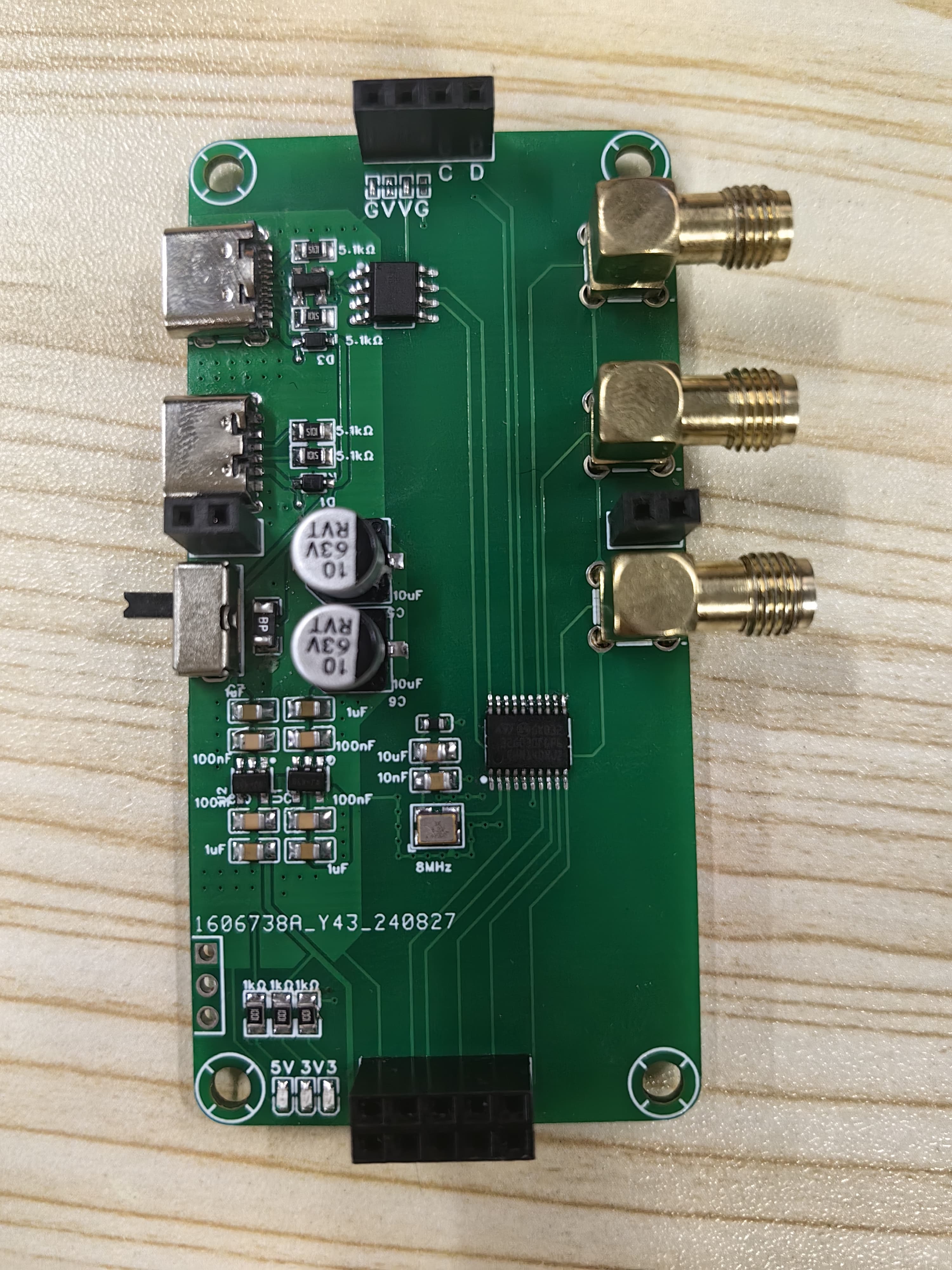
Figure 1: Front view of core board
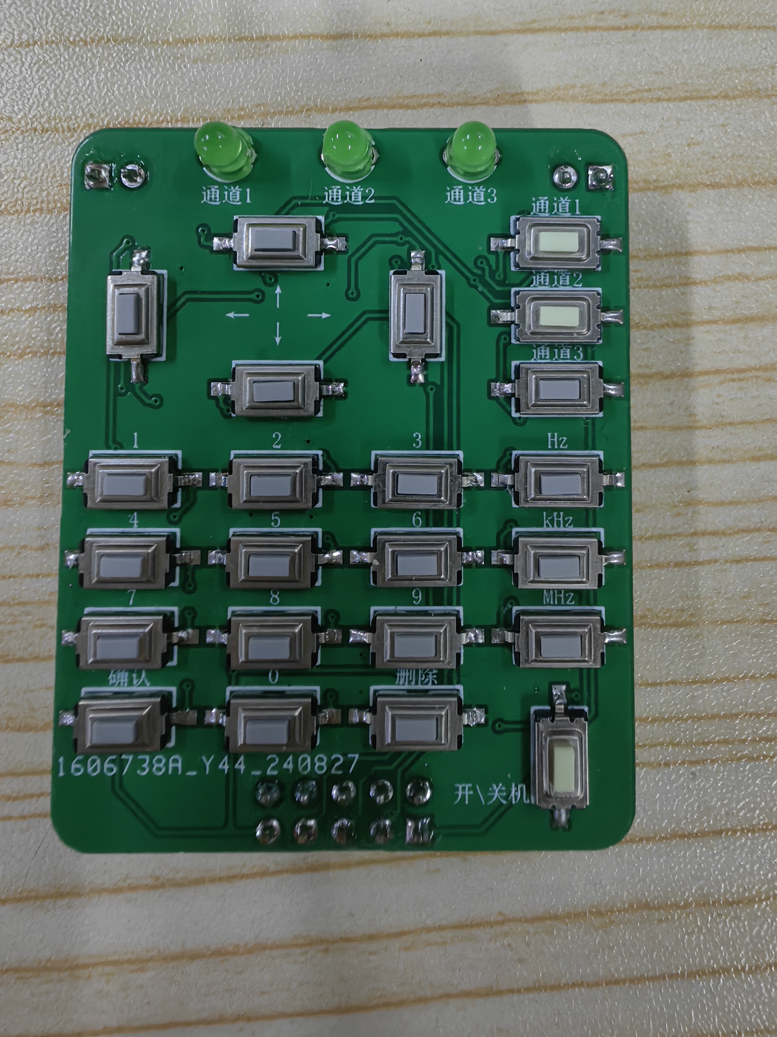
Figure 2: Front view of button board
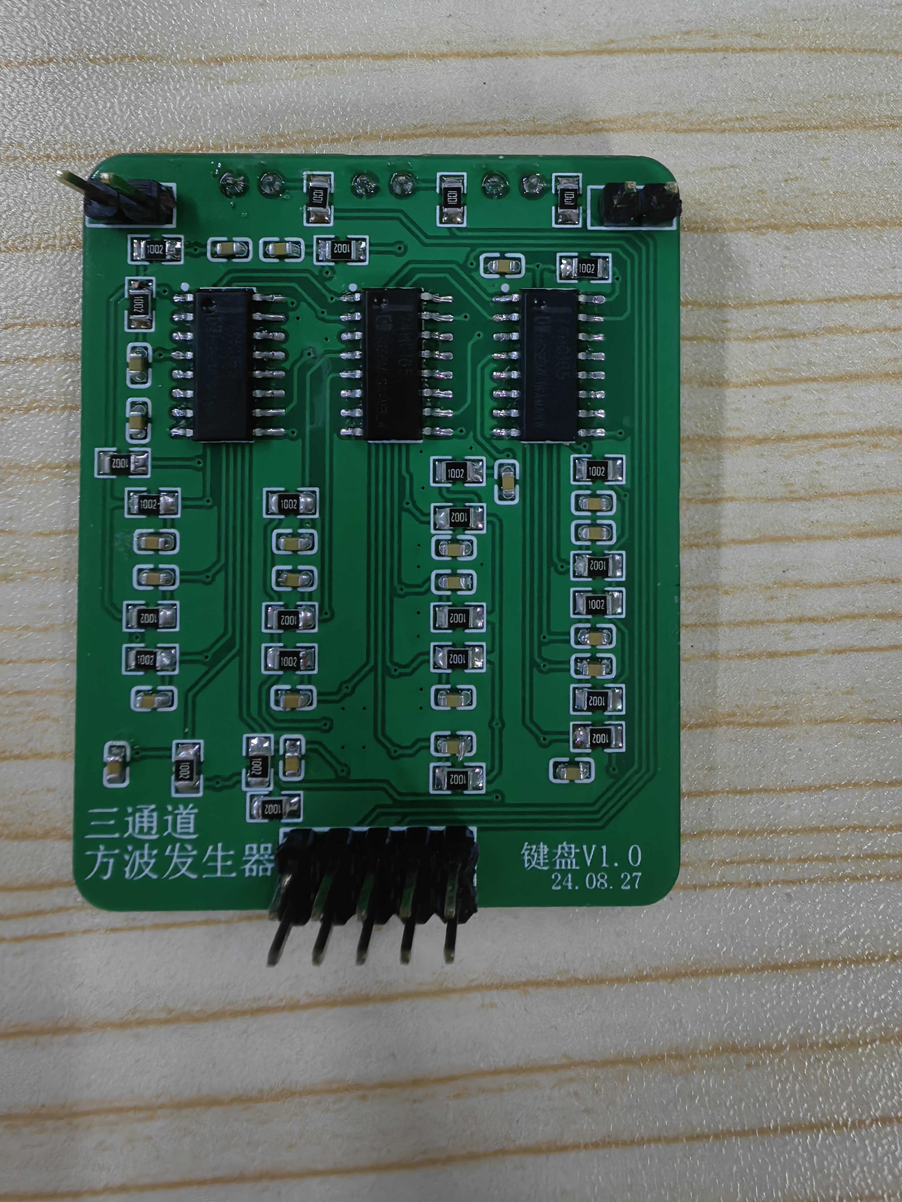
Figure 3: Back view of button board
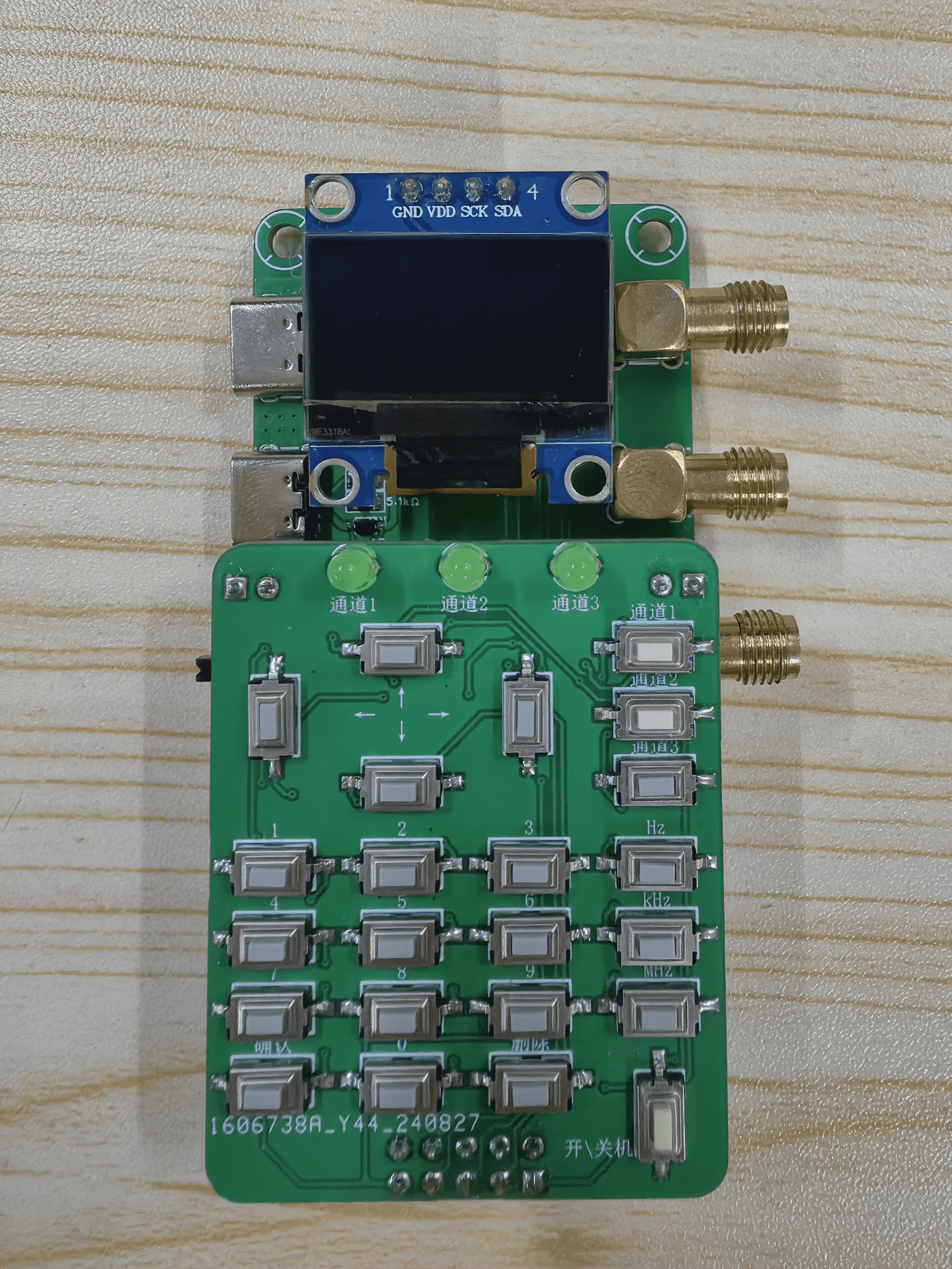
Figure 4: Assembly diagram
3-Channel-PWM.zip
VID_20240925_005833_compressed.mp4
PDF_Three-channel square wave generator circuit.zip
Altium Three-Channel Square Wave Generator Circuit.zip
PADS Three-Channel Square Wave Generator Circuit.zip
BOM_Three-channel square wave generator circuit.xlsx
90777
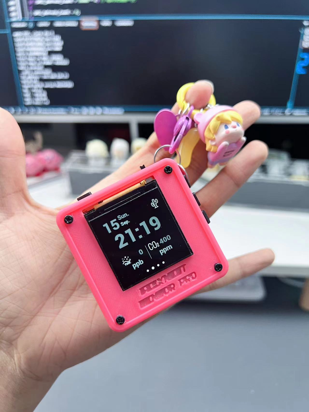
The final ESP32 toy: a sensor and space monitoring data aggregation station – a space environment manager.
This small toy integrates a temperature and humidity sensor, an air quality sensor, and a decibel sound volume sensor. It also supports obtaining geomagnetic and solar activity data from publicly available websites via WiFi. When connected to a charger as an external device, it can monitor the charger's operating status (charging voltage, current, and operating power).
Video Link:
Bilibili Video -- Function Demonstration
Project Introduction
It's been over a year since I started DIYing, and I've been using ESP series chips for MCUs. From not knowing what a serial port was at the beginning to handling the entire software and hardware of this project, it's been incredibly rewarding! So, to test my learning, I tried designing and building this little sensor toy.
Initially, I wanted this little thing to provide as much information as possible about the surrounding environment, including time, climate, ambient temperature and humidity, harmful gas concentration, noise intensity, light intensity, PM2.5 concentration, and even ionizing radiation intensity, which I had previously researched when building a Geiger counter.
Finally, considering the safety and size of the circuit, I decided to temporarily abandon the light intensity (I don't like it anymore), PM2.5 concentration (the module is a bit large), and ionizing radiation intensity monitoring functions (the boost circuit is a little dangerous & the Geiger tubes I researched are too large, and smaller ones are too expensive). I only retained the temperature and humidity sensor (SHT30), CO2, TVOC, and alcohol concentration sensors (SGP30), and the decibel sensor (LM2904). Doing only this felt a bit tedious, so we also incorporated inspiration from HAM fans—space environment monitoring data. The National Space Monitoring Center of the Chinese Academy of Sciences releases various interesting space data from its Space Environment Forecasting Center, some of which can affect radio wave transmission and are therefore familiar to some HAMs.
Website: http://www.sepc.ac.cn/
Since many of our main products are charging-related (power banks, chargers), we also designed a charging status monitoring page to display the charging voltage and current of each charging port on the charger. The Modbus protocol is used to enable data communication between the charger's MCU and the administrator's MCU.
Project Function
Screen Display:
A total of 4 pages, rotating periodically.
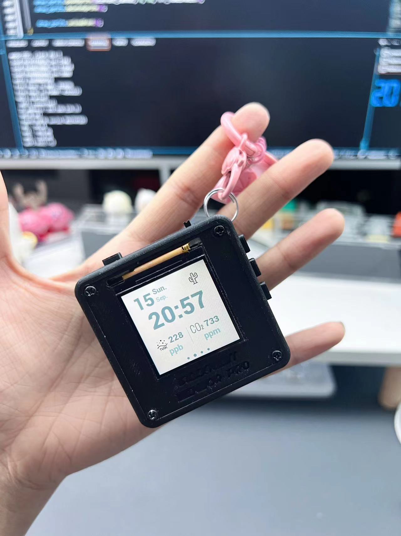
The ambient temperature page displays the date, weather, ambient temperature, humidity, and noise level in decibels (minimum value is 40dB due to sensor limitations).
The air quality page displays the date, time, TVOC, and CO2 concentration data
. The spatial environment page displays geomagnetic and solar activity data.
The charger status monitoring page displays the charger's charging status and the voltage and current output of each charging port. The charger currently uses a self-developed 1-to-3 charger (not open source). If you want to achieve similar charging interface data monitoring, you need to ensure that your charger is programmable.
There are two display color schemes: "Daytime Mode" and "Nighttime Mode," automatically switching between them at 7 AM and 7 PM respectively.
To use:
after tossing the switch in the upper right corner to the left, long-press the top right button 1 to open the administrator account. Other interactive functions are not yet designed.
How is this different from previous open-source projects?
To allow more learning enthusiasts to understand how the functions are implemented and to facilitate their own adjustments and creations, the complete source code will be open-sourced this time (this is all done by Lulu; please be gentle with any errors, bugs, or awkward writing style).
As for the software used, how to write code on macOS, how to write functions, what environment can run the source code, how to compile, etc., please don't ask me. You can seek publicly available tutorials and materials; I've already taught these in my previous videos.
The project
uses an ESP32 chip + 64M bit flash + 64M bit PSRAM chip design, without using off-the-shelf modules.
It uses both battery power and external power supply, switched via a toggle switch. If it doesn't suit your preferences, remember to modify it.
The purchased SHT30, SGP30, and LM2904 modules can be easily plugged into the back of the board. If you encounter circuit design problems, this can also improve the utilization rate of the sensor modules. It features
a 1.54-inch LCD screen, ST7789,
and has reserved space for a Class D amplifier MAX98357 and a microphone MSM261S4030H0R, as well as a speaker jack. If you need sound-related functions, please write your own code to control and modify them.
Regarding the charger's charging status monitoring, the charger we use is not open source. The software code already contains the complete code logic for charger monitoring. Please refer to your charger's hardware specifications and redevelop the program accordingly to achieve similar monitoring functionality.
The casing file is attached. If you are familiar with SolidWorks, you can edit the part files.
The
software code
is shared via Baidu Cloud: SensorSpaceController.rar
Link: https://pan.baidu.com/s/1HNA90nkJLDsiK2qUvP5Rzw?pwd=xr44
Extraction code: xr44
Notes :
Components are based on the BOM;
the casing structure design is not ideal, making the screen prone to failure. It is recommended to move the screen's interface slightly towards the center of the board and change the screen interface from soldering to plug-in connection to improve screen reusability.
In addition to the components mentioned in the EDA project file, you may need to purchase the following parts:
an IPEX 4th generation Wi-Fi antenna (length optional) to ensure Wi-Fi connectivity;
and four M24 and M212 black metal screws. (4) M24 dual-through studs (4), M2*20+6 single-through studs (4);
1.54-inch LCD, driven by ST7789;
SHT30 temperature and humidity sensor module, SGP30 air quality monitoring module, LM2904 decibel monitoring module
panel. Panels can be directly customized from JLC using the panel in the project file to protect the screen;
Assembly process
Bilibili video -- Functional demonstration
and physical photos.
Parts_3D.rar
PDF_ESP32 Final Toy: Sensor & Space Monitoring Data Collection Station - Space Environment Administrator.zip
Altium_ESP32 Final Toy: Sensor & Space Monitoring Data Collection Station - Space Environment Administrator.zip
PADS_ESP32 Final Toy: Sensor & Space Monitoring Data Collection Station - Space Environment Administrator.zip
BOM_ESP32 Final Toy: Sensor & Space Monitoring Data Collection Station -- Space Environment Administrator.xlsx
90778
electronic


 京公网安备 11010802033920号

 JANTXV1N3046BUR-1


