Project Description:
* High-voltage, low-current programmable DC power supply * Two outputs, each with independently configurable positive and negative power rails * Parameters can be set via joystick and knob * Parameters can be set via two RS232 serial ports * Voltage and current stabilization, current and voltage stabilization output * Output with self-resetting fuse * All communication ports are fully isolated
Key Parameters (Significant Digits and Precision)
* Positive power rail voltage: 0~100.0V * Negative power rail voltage: -100.0~0V * Maximum current output capability: 10.000mA
Applications:
Used as a simple source meter, for rough measurement of volt-ampere characteristic curves, testing of glow tubes, electron tubes, electrotherapy devices, etc.
Open source description:
Design concept
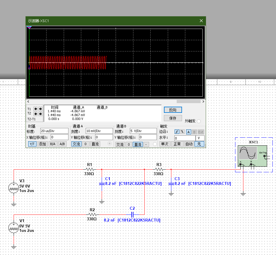
* 1 high-voltage isolated power supply, accepts 12V input, outputs -100V, 0V, 100V * 2 5V isolated power supplies, most circuits use -100V as reference ground (hereinafter referred to as low side), a small part of the circuits use 0V as reference ground (hereinafter referred to as high side), and the two parts can communicate in isolation * Uses STC advanced PWM controller to output complementary PWM, followed by 2-stage RC low-pass filter to output low-ripple analog signal (v0.0.2 has been abandoned because the PWM frequency cannot be increased, there is still obvious ripple, and changing the RC filter parameters will affect the response speed) * Uses MS5614T 4-channel 12-bit DAC chip outputs analog signals. * High-voltage operational amplifier HV264 is used for low-voltage to high-voltage proportional conversion, using the default gain of 66.7. * Fast recovery diodes are used for high-voltage level clamping, followed by emitter follower current amplification. * Texas Instruments INA281 is used for current measurement. The chip's common-mode voltage tolerance is only 110V, so two are placed on the low-side and two on the high-side. * An eight-pin secondary MCU, STC8G1K08A, is added to the high-side for high-side analog signal reading. It communicates with the low-side main MCU via an isolated serial port for collaborative operation. * Slots are placed at the high- and low-voltage junctions to ensure good electrical isolation. Actual
product photos
updated 2024/08/12: v0.0.2. See attached

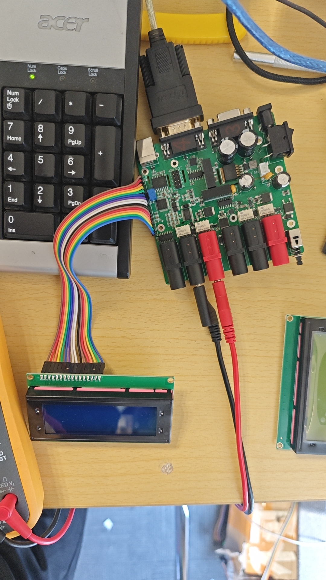
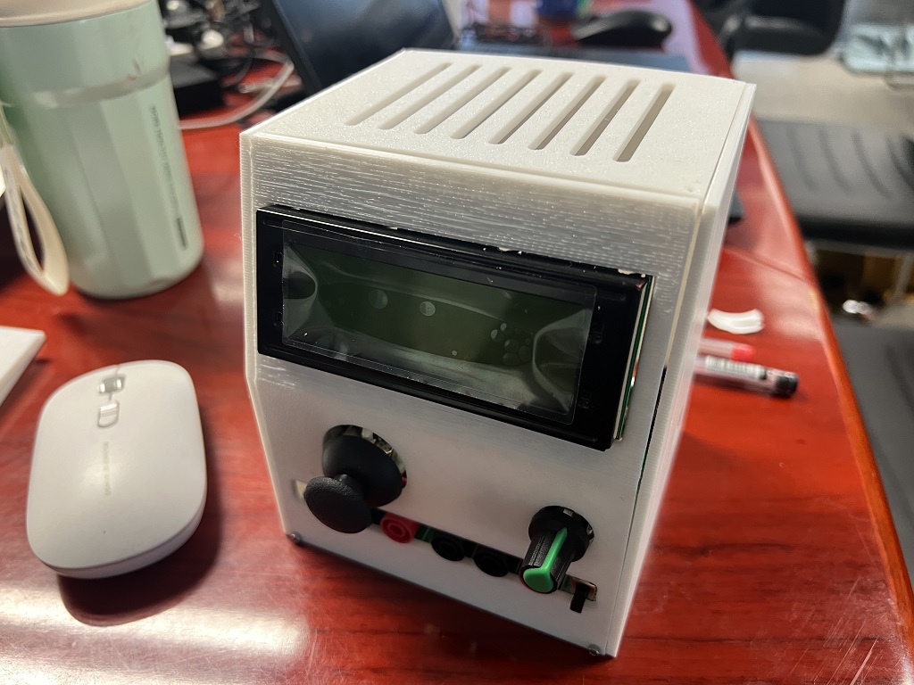
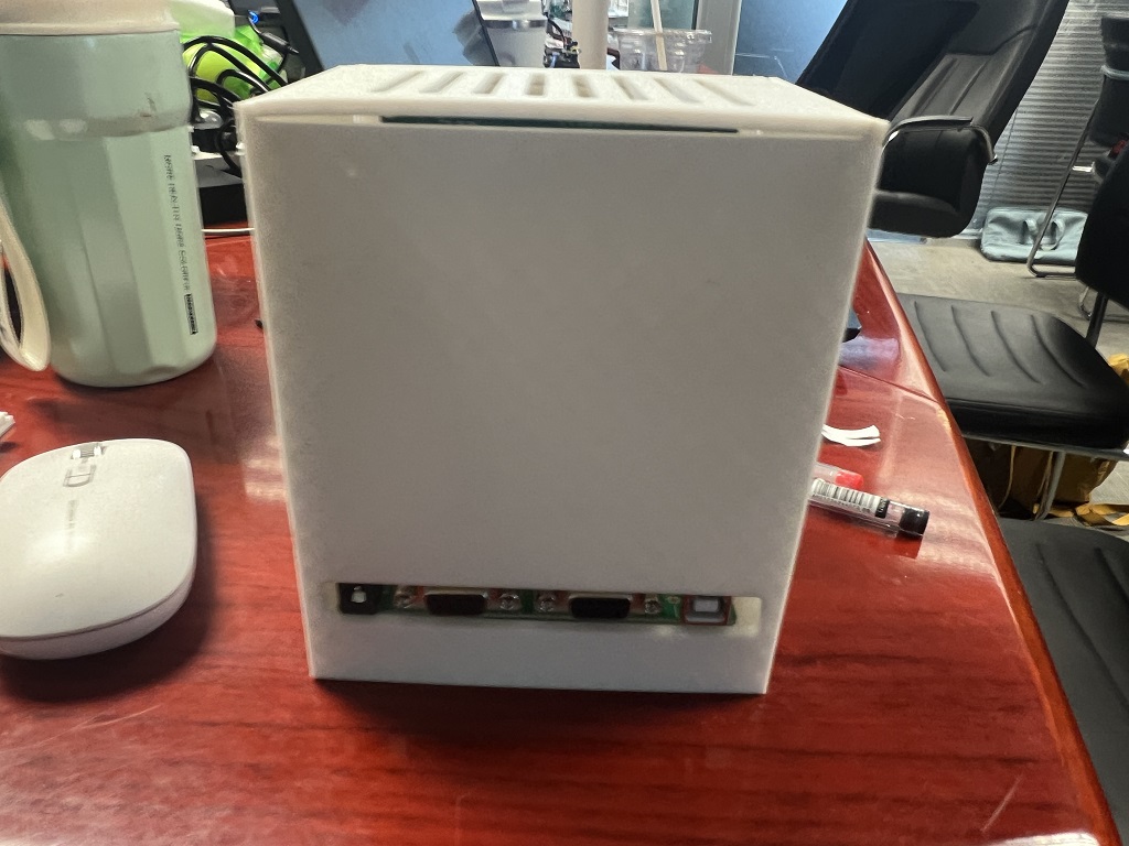
video of the actual product during SMT prototyping (currently using serial command control; videos of connecting the joystick and rotary encoder, load testing, and the complete product after enclosure installation are to be added). Some simulation process records. v0.0.2 update log (2024/08/12) * Improved code folder organization structure, making it more standardized. * Fixed several issues in version v0.0.1. * Used a DAC chip to output analog signals. * Made some layout adjustments. Issues in version v0.0.1: 1. Isolated USB could not enter USB-ISP mode to download programs. Temporary solution: fly wire, serial port download. TODO: Also test on a new board. USB download, add pull-down resistors to the data lines as needed. 2024/08/12 Update: v0.0.2 reserved D+ and D- pull-down resistor pads on the back. 2. CJ431 reference source output voltage issue (expected 3.05V, actual 2.70V) inconsistent with simulation results. TODO: Also test on a new board. 2024/08/12 Update: v0.0.2 changed to use LDO to provide reference voltage. 3. P3.2 Switch level inverted (normally low level, high level when pressed, opposite to expectation) and no debouncing. Temporary solution: Enable INT0 interrupt response on rising edge, software delay debouncing. TODO: Correct schematic, add debouncing capacitor. Updated 2024/08/12: v0.0.2 fixed. 4. STC power failure download switch cannot be turned off, reason: AREF backflow. TODO: Change CJ431 input to controlled MCU_VCC. Updated 2024/08/12: v0.0.2 fixed, 3V3 LDO also uses controlled power supply. This is my first time using STC microcontroller and 51 core microcontroller for project design. My software background and analog electronics are not solid, and the time is tight, so there are many omissions in the design. Please give me more guidance, thank you!


 京公网安备 11010802033920号

 HLMP-EL55-HJK00


