1. Introduction:
I usually enjoy making all sorts of handicrafts, especially quicksand mahjong sets, and I've made quite a few over the past year. This time, I wanted to make a special quicksand mahjong set, combining my love of crafting with my professional knowledge, which resulted in this electronic quicksand mahjong set. By controlling the on/off state of LED beads, it simulates the flow of quicksand in real quicksand mahjong, with particles of different colors intertwining to create a cyberpunk aesthetic. For a detailed look, please see this video: I made an electronic quicksand mahjong set!!!
2. Hardware :
This project is an electronic quicksand mahjong set based on the LCSC SkyStar STM32F407 development board. The screen used is a 2.5mm pitch LED dot matrix screen from Microwave, with a resolution of 32×64. The MPU6050 module is used to obtain the horizontal and vertical acceleration of the particles in the electronic quicksand mahjong set. The power supply design references @小煜哥哥's simplified 18650 power bank solution using the IP5306 chip. It uses the IP5306 chip to charge a single 18650 lithium battery and boosts the battery voltage to 5V to power the LED screen and microcontroller.
The project works as follows: the MPU6050 module acquires the current x-axis and y-axis acceleration and transmits the collected acceleration data to the microcontroller via the I2C protocol. The microcontroller calculates the positions of all particles based on the acceleration data and displays the results on the LED screen. The schematic design is straightforward; simply connect the aforementioned circuits. The completed PCB board is shown in the figure.
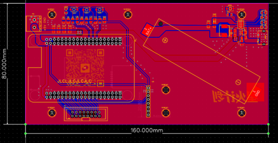
This PCB board measures 8mm*16mm, exactly the same size as the LED screen. Therefore, the PCB board is placed below the screen, and the two are connected using studs. The studs are positioned as shown in the positioning holes in the figure, corresponding precisely to the mounting holes on the LED screen. The two positioning holes in the lower middle are for securing the MPU6050 module, not the screen.
2.1 The connection between the LED screen and the base plate

is shown in the figure. Two cables are needed to connect the base plate and the screen: a data cable and a power cable. The screen manufacturer will include these two cables, but they are quite long and may not fit between the base plate and the screen. Therefore, a shorter cable is recommended. Shorter data cables can be purchased directly on Taobao, but shorter power cables need to be hand-forged. The data cable has a foolproof 2×8p connector to prevent reverse connection. For the power cable, be careful not to reverse the +5V and GND connections, otherwise it will burn out.
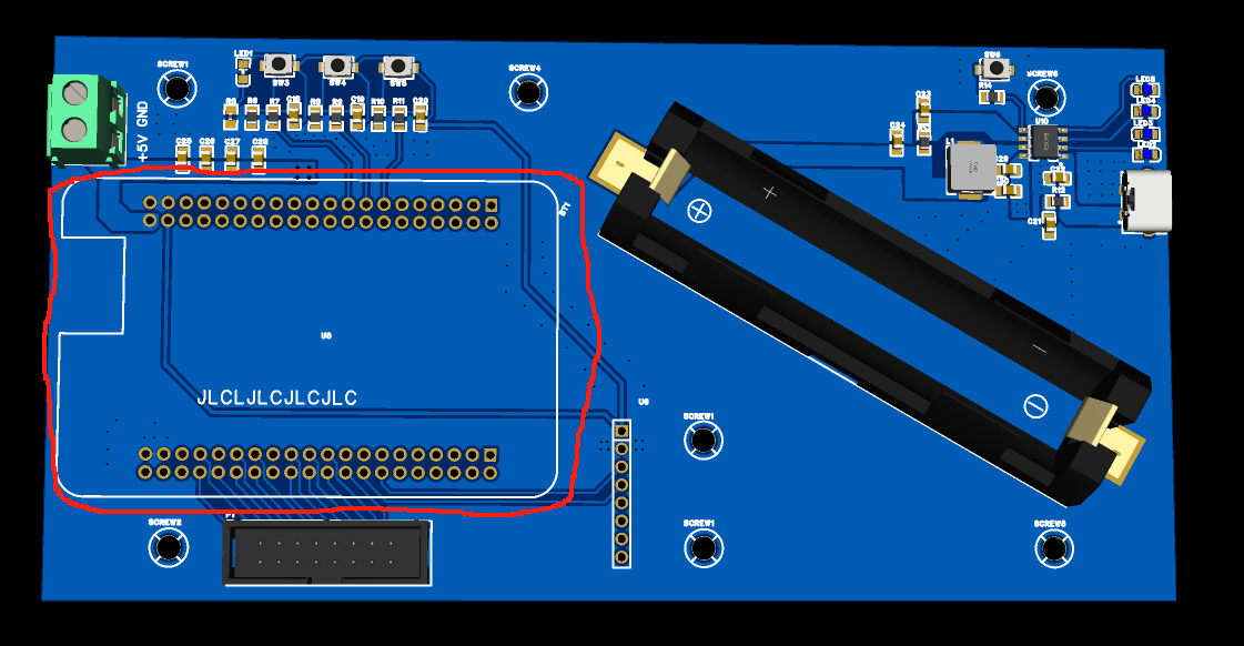
2.2 The connection between the core board and the base plate
involves soldering two 2×20p headers to the core board area on the PCB. Make sure the core board is inserted correctly; the serial and download headers should face outwards. Incidentally, the core board is shipped without headers; you need to purchase two 2×20p headers and one 2×5p header separately for soldering. When soldering the core board, the header pins should be soldered downwards. Be careful not to solder them backwards. A silly guy in our lab once soldered the header pins backwards, and I teased him about it for ages, haha. Also, don't solder the core board directly onto the PCB. Doing so makes it difficult to reuse the core board. Using a female header and header pin connection is better.
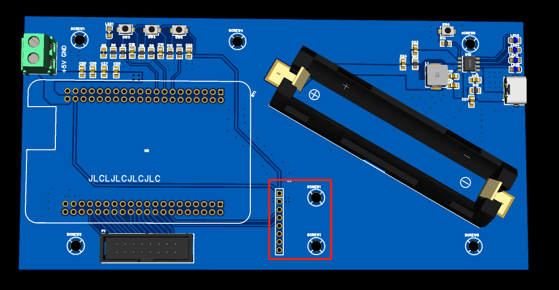
2.3 MPU6050 Connection to the Baseboard
: On the MPU6050 area of the PCB, a 1×8p female header needs to be soldered. Make sure this female header is soldered correctly; it must be aligned straight. If it's misaligned, it will affect the accuracy of the acceleration.
2.4 Lithium Battery Charging/Discharging Circuit:
The lithium battery charging/discharging circuit uses the IP5306 chip. The ground of this chip is connected to the pin under the chip's surface, making soldering somewhat difficult. A hot air gun is needed for soldering, not a soldering iron. Other parts of the PCB baseboard can be soldered with a soldering iron. Additionally, this circuit board is powered by the Type-C interface on the right side of the PCB, not the Type-C interface on the core board. The reason is that the Type-C interface on the core board has a small load capacity, and the current should not exceed 1A. However, the LED screen draws more than 2.5A under full load (of course, the current required for electronic current control is far from the full load current). The information provided by the screen manufacturer states that using the core board's Type-C interface for power supply may burn out the core board. I don't know if the consequences are really that serious, but using the Type-C interface on the right side of the PCB board for power supply should definitely be fine. Also, be careful not to reverse the positive and negative terminals of the lithium battery box.
2.5 Switches
The entire PCB board has four push-button switches. The three on the left are not currently used and can be left unsoldered. The switch in the lithium battery charging and discharging circuit area on the right must be soldered; it is the electronic current control switch. A short press turns on, and two consecutive short presses turn off.

3. Software
The software part of this project is programmed using Keil5 with CubeMX, so the HAL library is used.
3.1 For the MPU6050 module,
I referenced the source code for software I2C reading and writing of the MPU6050 from the STM32 tutorial at Jiangsu University of Science and Technology. The `MPU6050_GetData` function can be used to read the current values of the six-axis gyroscope and accelerometer. In reality, this project only uses two of them: horizontal acceleration and vertical acceleration. Also note that the SDA and SCL pins used for I2C must be set to open-drain outputs, not push-pull outputs, in the program. Don't make the same mistake I did, spending two days figuring this out.
3.2 Define and initialize the structure
: `typedef struct {
float Acce_x;
float Speed_x; // Current particle x-axis velocity
float Displacement_x; // Current particle x-axis displacement
uint16_t Position_x; // Current particle x-axis position
float Acce_y;
float Speed_y; // Current particle y-axis velocity
float Displacement_y; // Current particle y-axis displacement
uint16_t Position_y; // Current particle y-axis position
uint16_t Color;
uint16_t Index;
float Random_Acce;
} easy_pixel;`
This part of the code defines some information about a single particle, such as acceleration, velocity, displacement, position, and color. Initializing a particle means assigning values to the above information. For example, at the beginning of a video, the pixels are arranged neatly; colorizing them is the initialization process.
3.3 Update the acceleration, velocity, and displacement of a single particle sequentially :
As we learned in high school physics, the cumulative acceleration over time is velocity, and the cumulative velocity over time is displacement. Or, to put it more precisely, the integral of acceleration over time is velocity, and the integral of velocity over time is displacement. In a program, integration can be easily implemented. Simply define a minimum time unit, multiply the acceleration obtained in each loop by this minimum time unit, and then sum them up to get the velocity. Similarly, accumulating the acceleration yields the displacement. When the displacement exceeds 1, it means the particle should move one unit.
void Update_State(easy_pixel* p, float AX, float AY)
{
Update_Acce(p, AX, AY);
Update_Speed(p);
Update_Displacement(p);
}
3.4 Update the information of all particles.
This project has a total of 512 particles. That is to say, repeating the steps in 3.3 512 times will complete the update of all particles in one go. The function in 3.4 is written in a while (1) loop, which allows the program to continuously update the state of all particles, so that the quicksand can flow on the LED screen.
void Update_Group_State(easy_pixel* p, float AX, float AY)
{
for(uint16_t i = 0;i < Init_Height * Init_Width;i++){
Update_State(p, AX, AY);
p += 1;
}
}
3.5 The summary
flowchart is as follows:
graph TD
Start --> Initialization --> MPU6050 reads acceleration data
MPU6050 reads acceleration data --> Update single particle acceleration --> Update single particle velocity --> Update single particle displacement --> Have all particles been updated?
Have all particles been updated? --Y --> MPU6050 reads acceleration data Have
all particles been updated? --N --> Update single particle acceleration
I did not add a delay in the loop because the actual test showed that the MPU6050 took a lot of time to read the data, so a delay was not needed.
4. Component List
Here I have listed some components that need to be purchased from Taobao.
The following are essential purchases:
LED screen (2.5mm pitch, 32×64 resolution, RGB full-color LED display with adjustable brightness), HUB75 interface, DIY screen compatible with
MPU6050 modules (select straight pins for soldering MPU6050 modules), 3D angle sensor (6DOF, three- or six-axis accelerometer, electronic gyroscope)
, one 18650 lithium battery (any capacity is acceptable), and
copper pillars (there are quite a few to buy).
These are used to connect the LED screen and the base plate. I measured the highest point of the soldered base plate to be around 25mm, so theoretically, copper pillars of 28-35mm length are acceptable. I chose 35mm because I wanted to be able to insert my finger into the gap to press the reset button on the core board. M3*35+6 single-ended studs
are used to connect the base plate and the MPU6050 module. M3*11mm double-ended copper pillars
are used to fix the copper pillars. Note that the flat-head screw head is a bit large, so only one screw can be tightened when fixing the MPU6050. Perhaps using round-head screws would be better. One M3*4mm flat-head screw and
one ST-Link programmer are needed for downloading programs.
The following are optional purchases (buying them will improve the final display effect):
This data cable connects the base plate to the LED screen; 5cm long 2×8p 2.54mm gray ribbon cable; LED screen JTAG download cable. The
LED screen power supply cable is slightly more complicated, requiring the following two wires to be soldered together:
100mm single-ended VH 3.96mm pitch colored electronic connection terminal wire, 4P
red and black, one each; 17AWG 1m high-temperature resistant ultra-soft silicone wire for model aircraft;
LED light distribution board, just buy one larger than 8cm×16cm, thickness can be 0.5mm. The ones I bought myself might be a bit expensive, so I won't post the link.
Other components can be purchased from JLCPCB. Please make sure you check the components carefully before ordering!! Make sure you check the components carefully before ordering!! Make sure you check the components carefully before ordering!! Don't buy the wrong ones and waste money.


 京公网安备 11010802033920号

 G5A-234P


