 Soldering process and precautions:
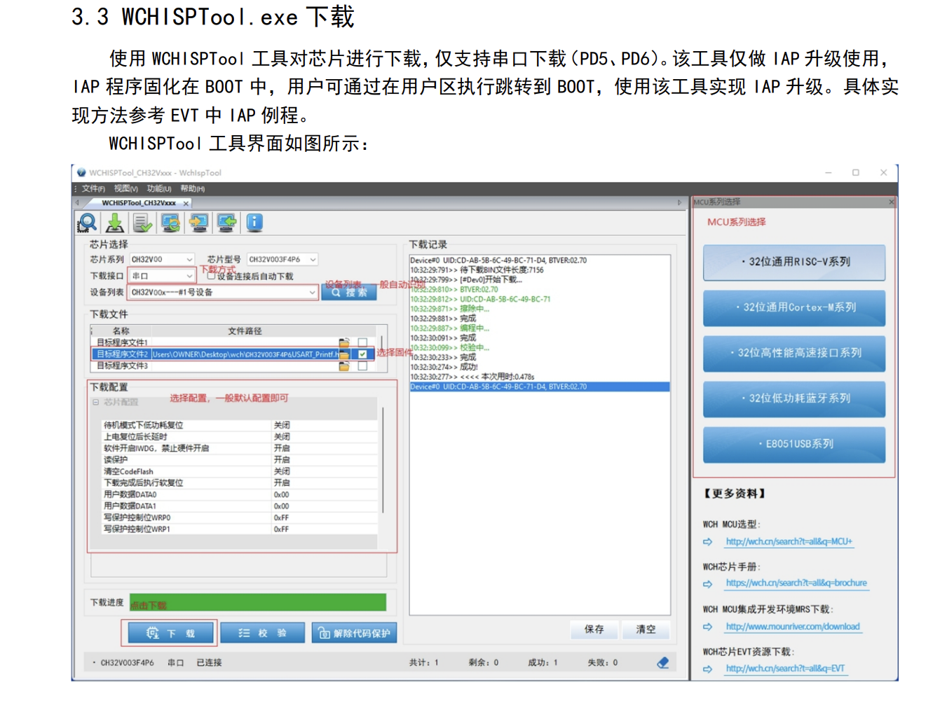
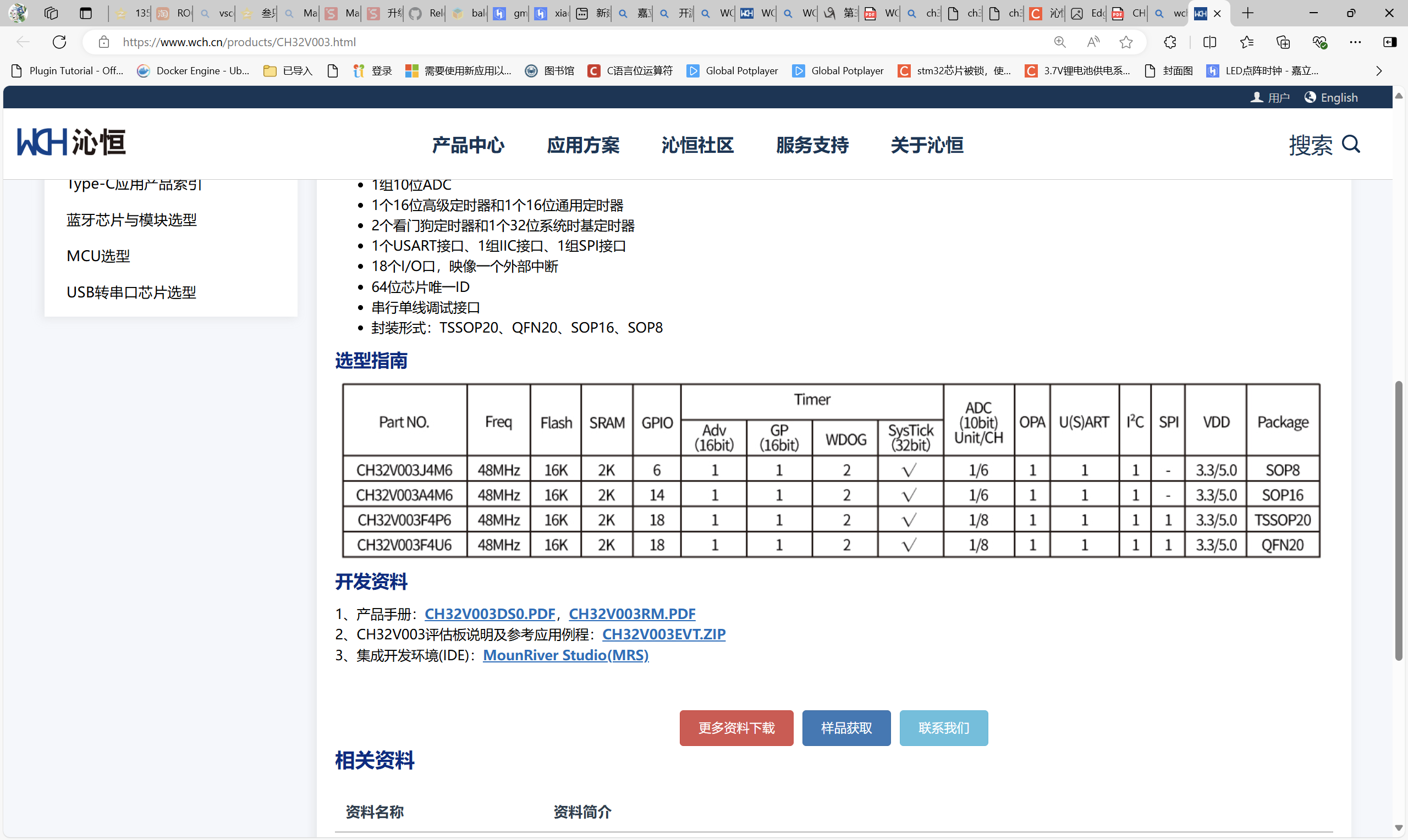
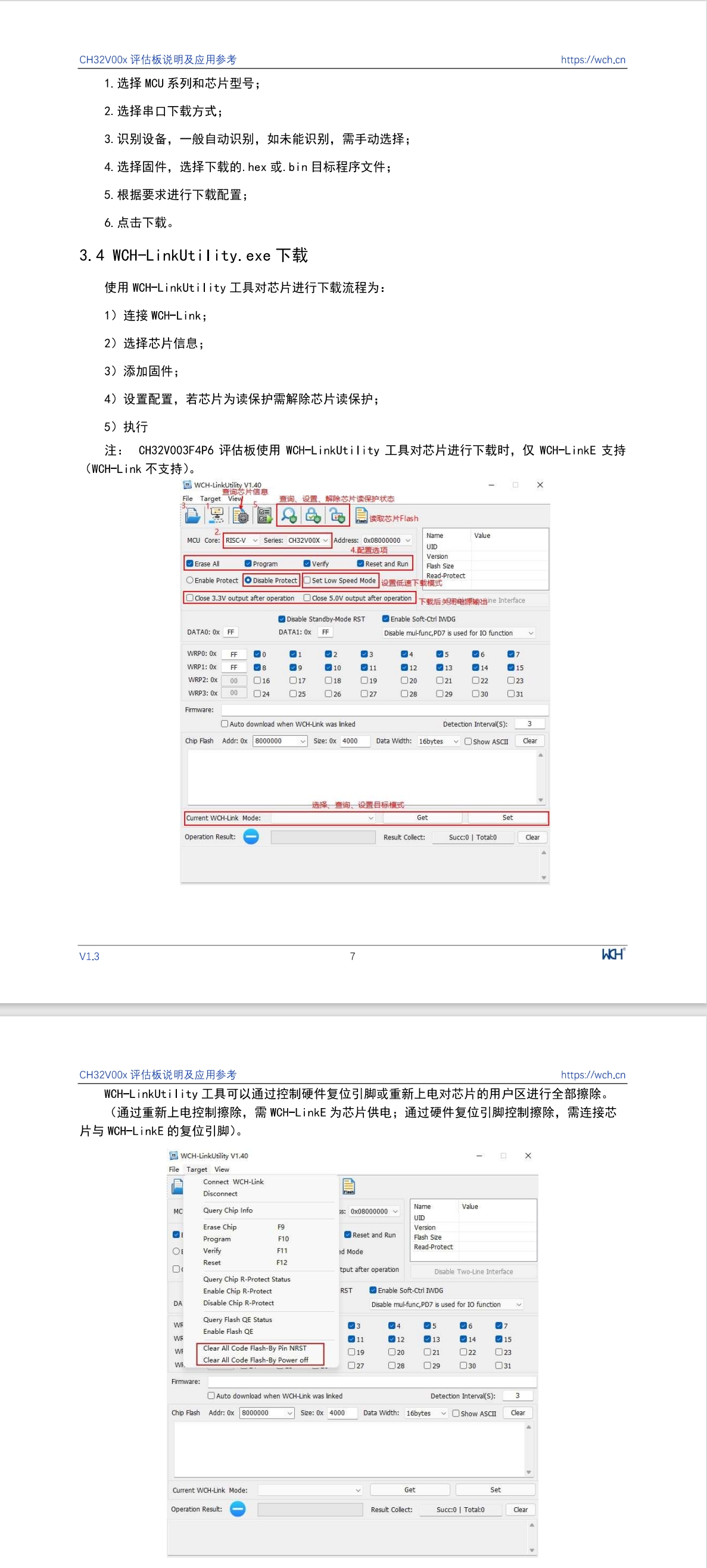
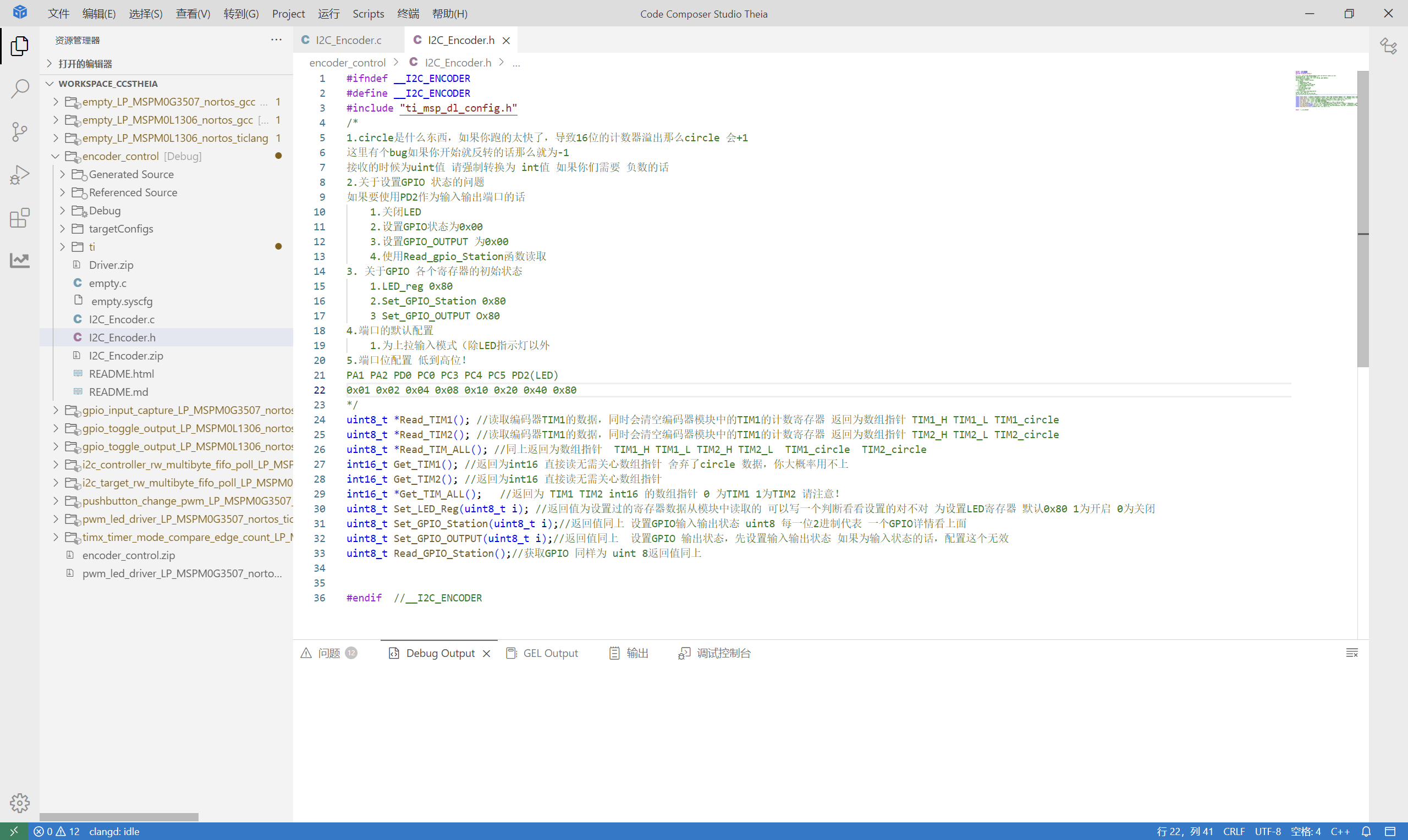
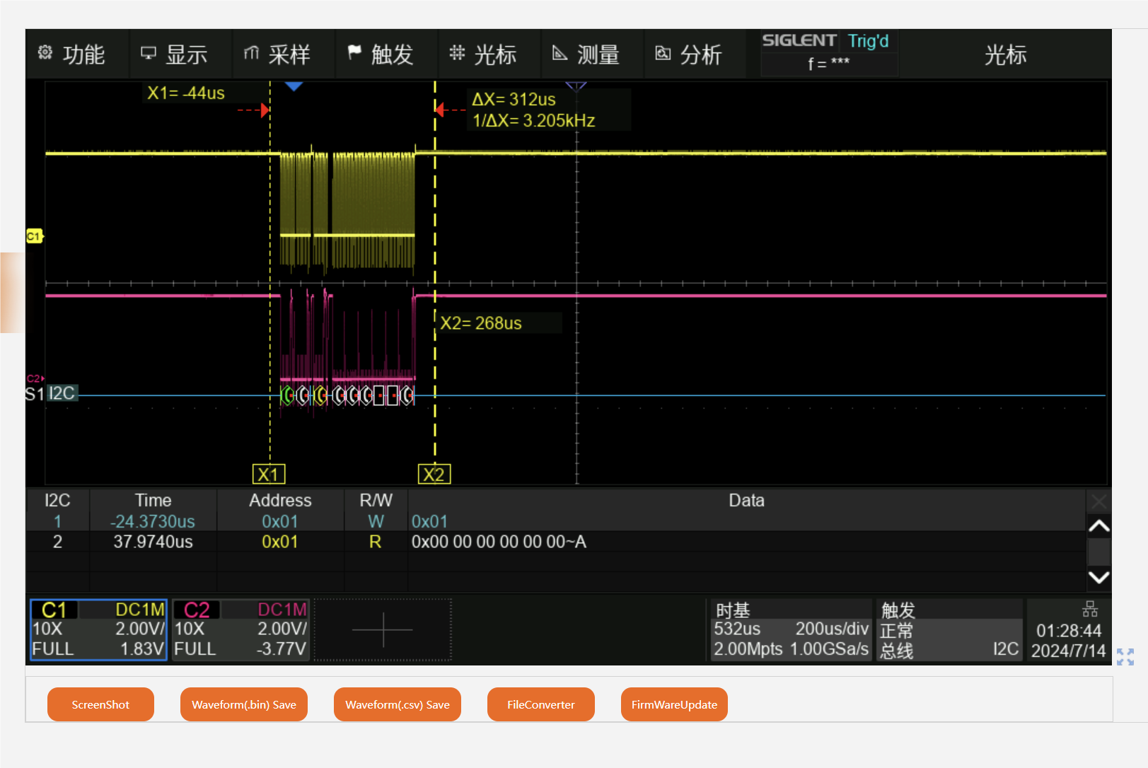
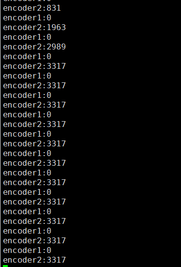
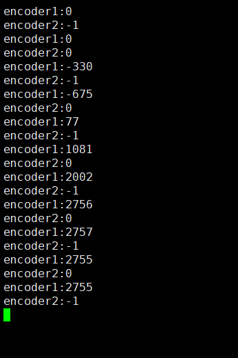
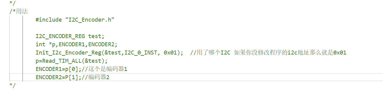
 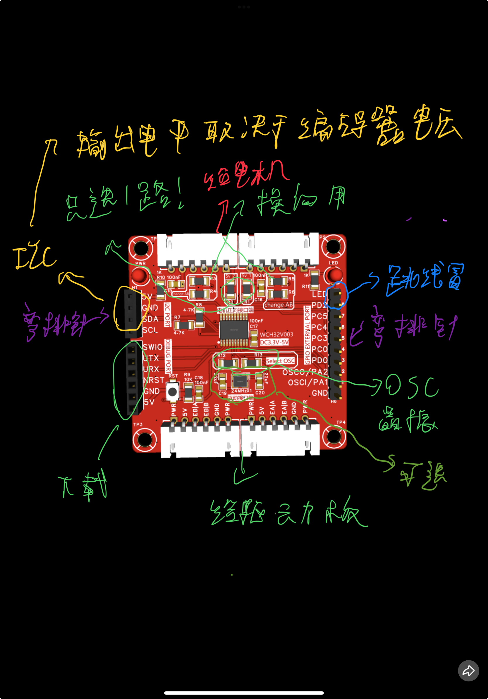 the attached image for a complete tutorial...) Program Notes: The program uses Mount River. This part is written in Studio and most people won't need it. TIM1 provides the encoder commutation information for motor A, and TIM2 provides it for motor B. If you move the motor to the back, it will cause TIM1 and motor A to be in reverse, so hardware or software commutation is required. Here's a method for software commutation; for hardware commutation, simply solder the resistors vertically (this is the third time I've mentioned rotating 90°). Regarding program download via serial port (ISP), unfortunately, because of this, there's no way to download via ISP using wchlink (recommended because the wch32 chip is also RISCV, requiring their official downloader). (Wait a minute! The good news is, you can directly purchase an extended version + LinkE downloader with 5 chips from the official flagship store for only 26.8. This way you can download whenever you want.) There are two download methods: you can choose to directly download using the Mount River compiler and open the project to download, as this is relatively simple and won't be discussed here (go to wch32) . Downloading a sample program will give you everything you need, and you can also learn how to use this chip. Use the official tools to download (I'm being lazy and just using screenshots ; you'll need a downloader!!!). Remember to download the HEX file. The driver usage guide uses CCS, but you can definitely use Keil! Just add the .h and .c files to the above. The header file is explained very clearly QAQ. Test images: 100kHz to get all encoder values; 400kHz to set GPIO status. I'm too lazy to set up two encoders. UART output encoder data. Regarding hardware, most can be purchased from JLCPCB. If you don't have a wchlinkE downloader, buy a development board from the official website www. For usage instructions, contact us. Special thanks to the contributor for refactoring the I2C driver code in this project (it was a huge help, thank you!). Also, please follow this Bilibili account if you can (follow the one above too!).


All reference designs on this site are sourced from major semiconductor manufacturers or collected online for learning and research. The copyright belongs to the semiconductor manufacturer or the original author. If you believe that the reference design of this site infringes upon your relevant rights and interests, please send us a rights notice. As a neutral platform service provider, we will take measures to delete the relevant content in accordance with relevant laws after receiving the relevant notice from the rights holder. Please send relevant notifications to email: bbs_service@eeworld.com.cn.
It is your responsibility to test the circuit yourself and determine its suitability for you. EEWorld will not be liable for direct, indirect, special, incidental, consequential or punitive damages arising from any cause or anything connected to any reference design used.
Supported by EEWorld Datasheet
EEWorld
subscription
account

EEWorld
service
account

Automotive
development
community

Robot
development
community

About Us Customer Service Contact Information Datasheet Sitemap LatestNews


Room 1530, 15th Floor, Building B,
No.18 Zhongguancun Street,
Haidian District,
Beijing, Postal Code: 100190
China
Telephone: 008610 8235 0740
 京公网安备 11010802033920号

 IDT74FCT16500ETPV


