November 10, 2024 Update Log: Added test screenshots for the cat stick.
I. Preface
- 1. You shall bear all security and legal risks arising from replicating, iterating, or modifying this design.
- 1. You shall bear all security and legal risks arising from
replicating, iterating, or modifying this design. - 1. You shall bear all security and legal risks arising from replicating, iterating, or modifying this design.
You may not use this design for commercial purposes!
You may not use this design for commercial purposes!
You may not use this design for commercial purposes!
0. The price of 2.5G SFP transceivers on the market is outrageously high, with some transceivers even costing more than a 4x2.5G+2x10G switch. SFP transceivers on the market are too bulky and unsuitable for home users with small weak current boxes.
1. This design uses the RTL8221B chip to implement a 2.5G fiber optic transceiver. The SFP rate is fixed at 2.5G (details explained below), and the network port supports 10M/100M/1000M/2.5G speeds.
2. This design uses a four-layer board design. The board dimensions are 20mm x 65.2mm x 1.6mm, and the matching housing dimensions are 28mm x 69.2mm x 21.4mm. Most materials can be purchased with coupons of 16-15 yuan, and even without coupons, the overall material cost can be controlled within 25 yuan.
II. My Requirements
1. Overall Requirements: The initial purpose of this design is simply to use fiber optic cable as the uplink for the home access point (AP). This allows me to place the AP in a central location in my home and connect it to the core switch in the internet access area of the server rack via fiber optic cable. I'm using the AX5400PRO as the access point (AP). This AP has a 2.5G Ethernet port. To maximize wireless bandwidth, a fiber optic transceiver that supports 2.5G, is easy to power (preferably USB), compact, and doesn't use inferior components is crucial.
2. Power Requirements:
Compact input interface (this design uses a 6-pin Type-C interface, which is easy to solder and inexpensive).
High conversion efficiency (both 0.95V and 3.3V power supplies use DC-DC converters, not LDOs), low heat generation (using synchronous Buck converters).
Chip output capability must meet the requirements of the chip and SFP module.
Therefore, this design uses my favorite DC-DC chip, the TPS563201, which is inexpensive (0.24/chip), has a high switching frequency, and a low failure rate.
3. Ethernet Port Requirements:
At least two indicator lights; wiring sequence must meet chip design requirements (this design uses the RTL8221B, which supports MDI SWAP, so this is not a concern).
The Ethernet port price cannot be too high, and the network transformer must be sufficiently compact.
In summary, this design uses a flat network transformer (G2425S) + network port (HC-WK88-H16-DB) (remember to use the 16-15 coupon from the online store when purchasing, which is practically free).
4. Layout Requirements:
This design aims for minimal size. The SFP, network port, DC-DC converter, main chip, network transformer, and a large number of configuration resistors and filter capacitors need to be squeezed together, so the layout method needs to be prioritized. This design ultimately adopts a layout where only the RJ45 and SFP are placed on the front, and all other components are placed on the back.
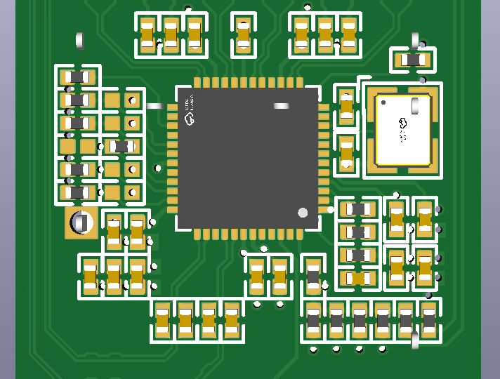
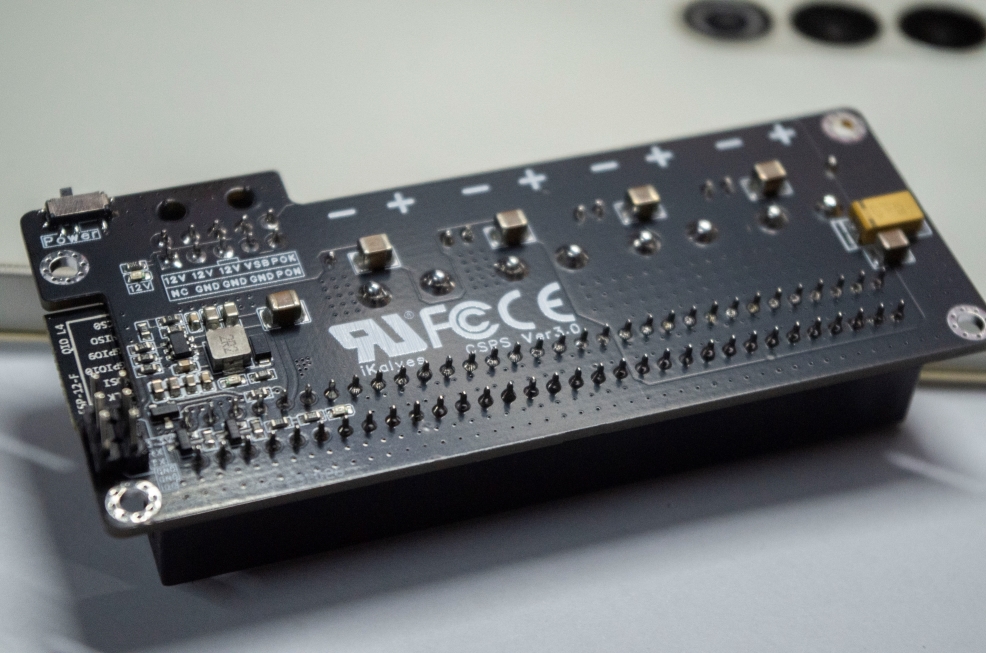
Front view:
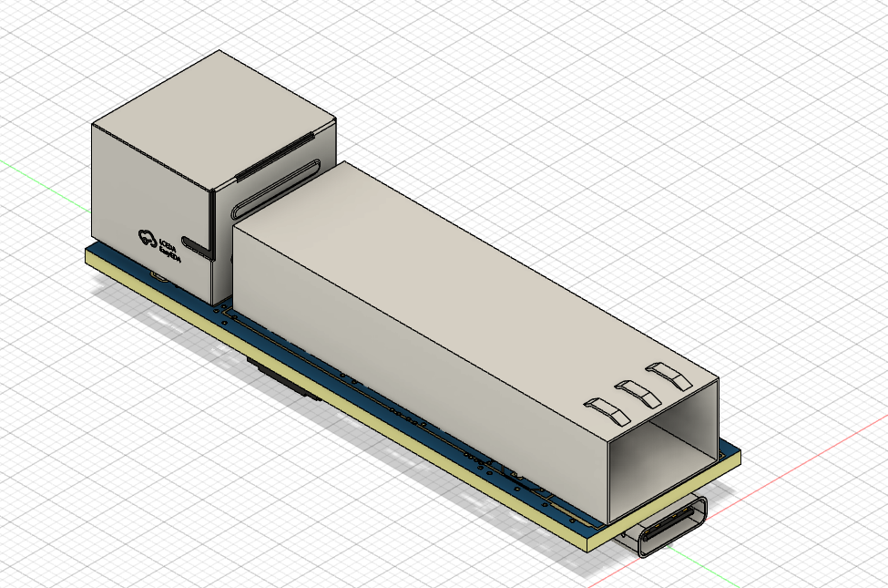
Back view:

This layout method can minimize the PCB size. However, because the TYPEC female connector and SFP cage are on top of each other, even with a board thickness of 1.6mm, the outer sheath of the TYPEC cable will interfere with the SFP module. Therefore, when using this design, it is necessary to scrape off part of the outer sheath of the TYPEC interface with a knife, or use a 10mm extended TYPEC cable (available on Taobao).
III.
Power Supply Design:
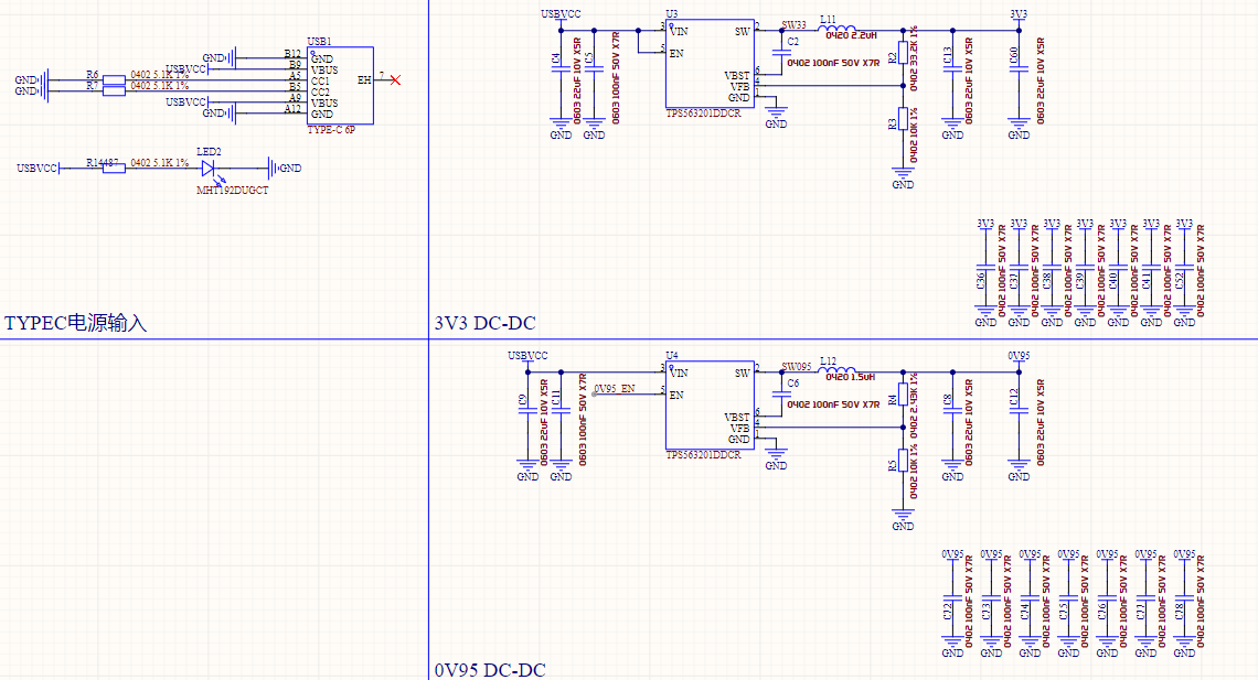
A Type-C female connector is used as the power input interface. 5.1K pull-down resistors are configured on the CC lines to support the CC wires.
Using TI's webench, the DC-DC circuit is built and laid out, resulting in the following design.
Note that the MLCC capacitor has bias characteristics. The pads for the DC-DC filter capacitor section in this design are designed to be 0603, but 0805 capacitors can actually be soldered. If you require a higher input voltage, you can solder 0805 capacitors yourself.
RTL8221 Main Chip Design:
The crystal oscillator and start-up capacitor are placed close to the main chip.
Filter capacitors and configuration resistors are placed as close to the main chip as possible (in the case of small size and single-sided layout, it is impossible to have filter capacitors near every pin).
Coupling capacitors are placed close to the main chip (due to space constraints, HSO and HSI coupling capacitors are placed close to the main chip).
Network Transformer and Ethernet Port Design:

The RTL8221's LED and PHYAD share pins. For design flexibility, the LED and PHYAD are configured in flexible mode. You can solder the corresponding resistors according to your needs. The specific soldering relationships are as follows:

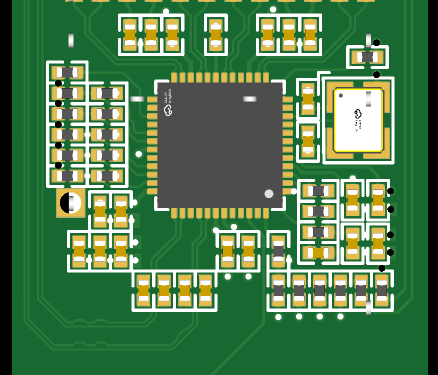
Generally, solder according to the red text (i.e., do not solder any marked NC). The final soldering effect should look like this:

4. SFP cage pin modification: This design has deleted most of the SFP cage pins (only 1, 8, 9, 10, 16, and 17 are retained, and the stability is not a problem in actual testing). Before soldering the SFP cage, be sure to trim the pins.
IV. Soldering
This design uses a large number of 0402 resistors and capacitors. It is recommended to use solder paste stencil + heating table for soldering.
The pads of RTL8221B have been elongated. If there is solder bridging after soldering on the heating table, use a pointed soldering iron + flux to smooth it out.
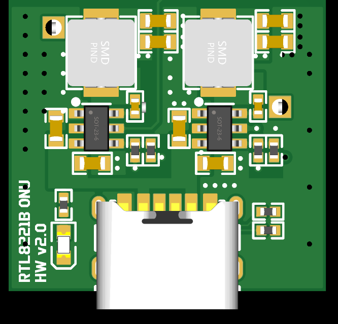
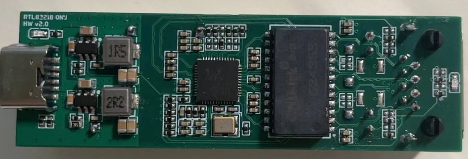
The soldering effect is as follows:
V. Testing
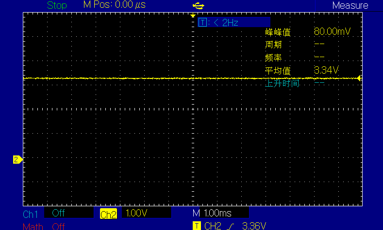
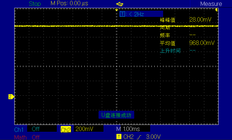
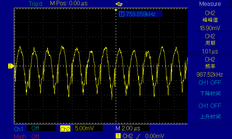
1. Test whether the voltage and ripple of the DCDC section meet the requirements. After actual testing, both voltage outputs are normal, the ripple also meets the expectations, and the chip switching frequency is not much different from the description in the manual.
3.3V voltage and ripple test screenshot:

0.95V voltage and ripple test screenshot:
2. RJ45 part test:
Connect a 2.5G device and check the link negotiation status. At this time, the green LED on the right side of the network port lights up.

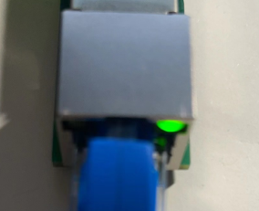
Connect a 1G device and check the link negotiation status. At this time, the yellow LED on the left side of the network port lights up.

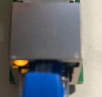
Connect a 100M device and check the link negotiation status. At this time, the LED at the bottom of the network port lights up.


3. SFP part test
: A certain H brand 2.5G 1310nm 2km optical module was used for testing.
The test peer device was an RTL8372N switch.
The SFP worked normally in the test (this design does not have a reserved SFP status indicator light
. You can modify this design yourself). Why did the transceiver not work normally when I inserted a 1G optical module? Because the default SGMII interface type of the RTL8221B is the HiSGMII interface, with a rate of 2.5G. You can add an external microcontroller and use the MDIO interface to change the SGMII interface type to the ordinary SGMII.
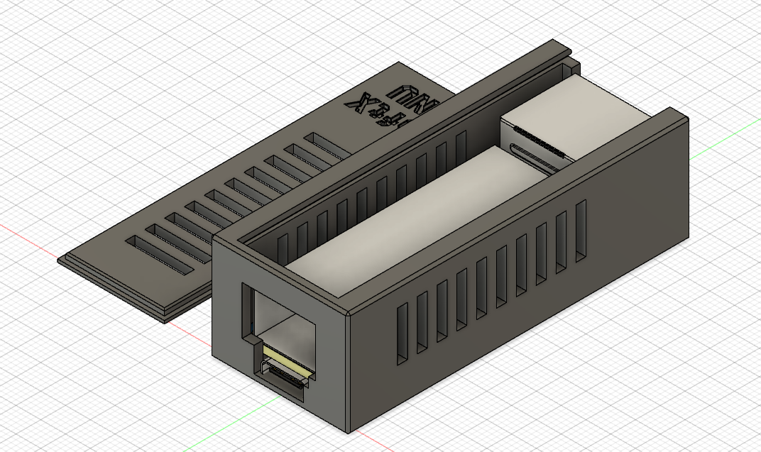
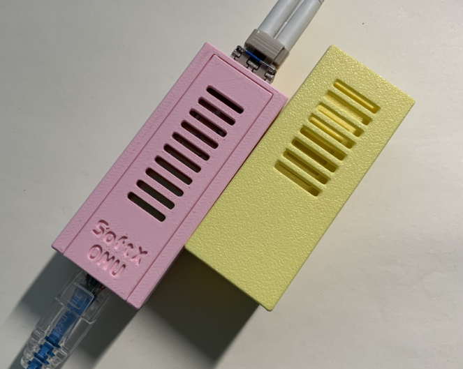
VI. Shell Printing
You can directly print the shell shown in the design appendix, or you can design your own shell.
It is recommended to use high-temperature resistant materials for printing.
VII. Pressure Testing
1. Ping Test

2. DPerf Streaming Test
Experimental Environment:
Physical Machine Configuration
| Key | Value |
| --- | --- |
| Host | M920X |
| OS | PVE 7.1 |
| CPU | G5420 |
| MEM | 2xDDR4-4G@3200MHz |
| DISK | MICRON 2200 1TB |
| NIC | SP310 |
VM Configuration
| Key | Value |
| --- | --- |
| OS | Debian 11 |
| CPU | 2vCPU |
| MEM | 3G |
| DISK | 50G |
| NIC | SP310(1Port) |
| Hugepage | 2M*1024 |
| DPDK Version | 23.11.2(LTS) |
| DPerf Version | 1.8.0-dev The physical
machine is an M920X with an SP310 network card. The two ports of the network card are directly connected to two VMs (this can be achieved by enabling PCIe ACS override).

Since the CPU does not support 1GB Hugepages, 1024 2MB Hugepages are allocated to each VM.

The network card is mounted to the DPDK protocol stack using the uio_pci_generic driver.

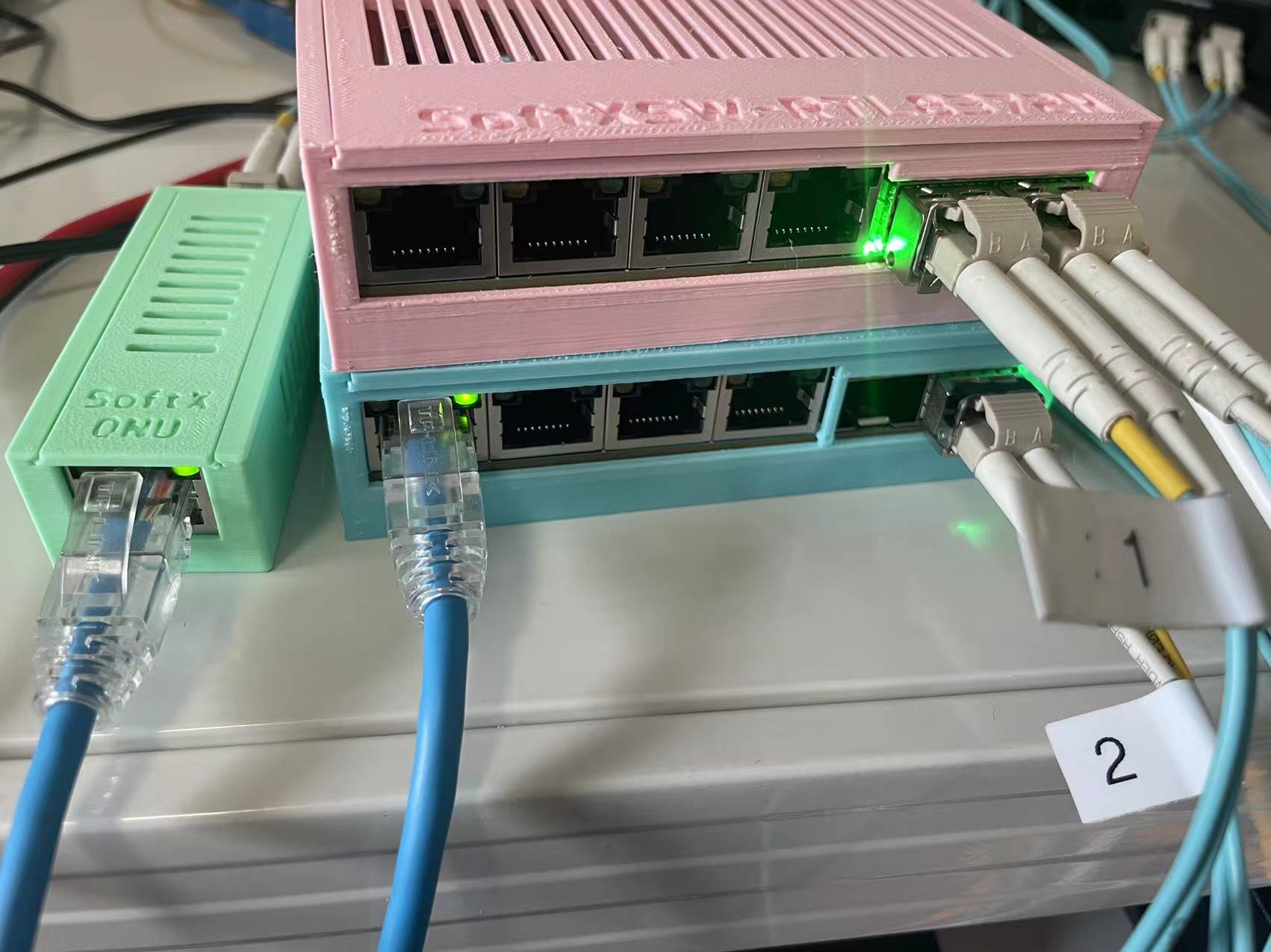
The test machines are named VM1 and VM2, and the system connection is shown in the figure.
VM1_10G <--10G--> SW1 <--2.5G RJ45--> SoftXONU <--2.5G SFP--> SW2 <--10G--> VM2_10G.
A unidirectional bandwidth test was performed on SoftXONU, yielding the following results (only the RX signals on both sides are considered; TX is meaningless):
RJ45 to SFP, speed approximately 2.459Gbps (1500 large packets);

SFP to RJ45, speed approximately 2.459Gbps (1500 large packets).
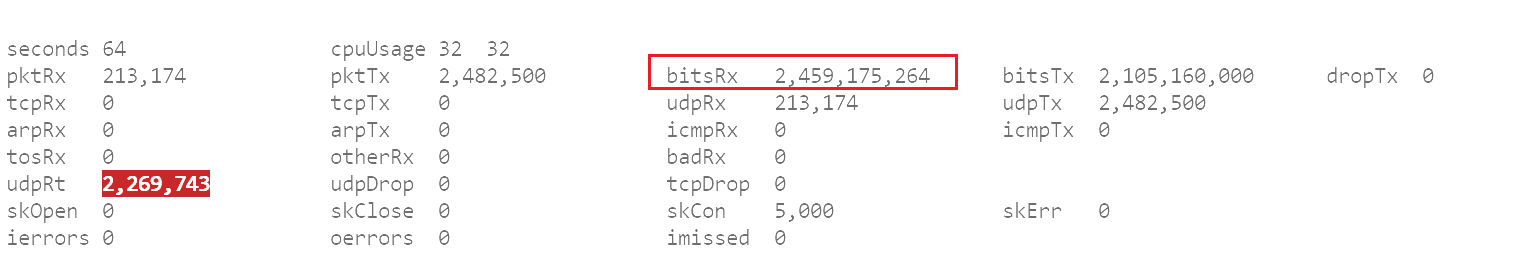
We can assume that SoftXONU can fully utilize the unidirectional bandwidth.
Bidirectional streaming was performed on the SoftXONU, and the following test results were obtained (full CPU usage on the client side is normal; the inability to fully utilize the bidirectional 2.5G bandwidth is not a bottleneck on the client side).
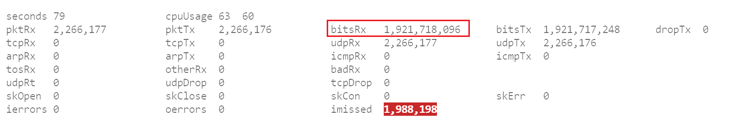
SFP to RJ45: speed approximately 1.921Gbps (64K small packets).
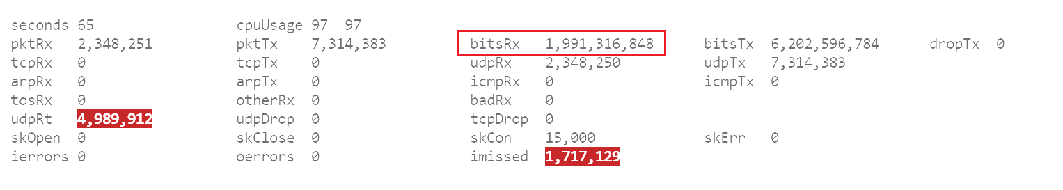
RJ45 to SFP: speed approximately 1.991Gbps (64K small packets).
The conclusion is that the SoftXONU cannot fully utilize the bidirectional bandwidth. This is likely because the SoftXONU uses gigabit network ports and adapters, which cannot meet the high bandwidth requirements of fully utilizing the bidirectional 2.5G bandwidth (2.5GBASE-T uses PAM16 code with a symbol rate of 200 Mega Baud, compared to 1000GBASE-T's PAM5 code of 125 Mega Baud; 2.5GBASE-T has higher requirements for network adapters and ports).
Compact 2.5G network adapters are hard to find on the market. If you have a more suitable 2.5G network adapter recommendation, please leave a message or send a private message!
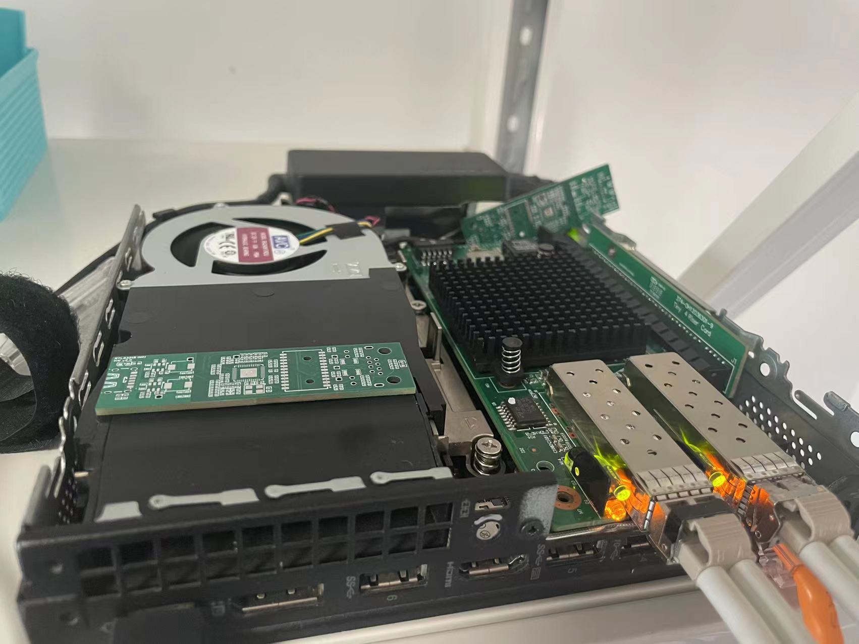
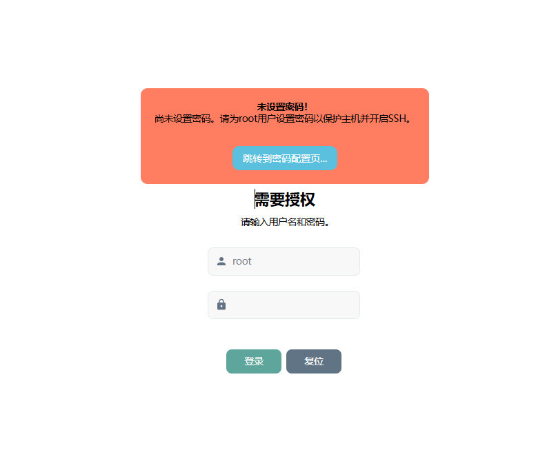
Screenshots of the Cat Stick test are as follows:
VIII. Design Demonstration

SoftXONU casing.step
Gerber PCB Design Files - SoftXONU - V2.0.zip
PDF_SoftXONU-2.5G Fiber Optic Transceiver.zip
Altium_SoftXONU-2.5G Fiber Optic Transceiver.zip
PADS_SoftXONU-2.5G Fiber Optic Transceiver.zip
BOM_SoftXONU-2.5G Fiber Optic Transceiver.xlsx
91137
CSPS-ATX12VO Smart Power Supply
The CSPS power supply intelligent power engineering project, including the power supply board, core board, and hard drive power supply board, is open-sourced for those who need it. The power supply board was inspired by the CSPS power supply board open-sourced by the user wuyu, and has been ported to the existing power engineering project. Some circuits have been modified to meet specific requirements.
CSPS Smart Power Supply
Project References:
【wuyu无语】Huawei 460W_CSPS Power Supply_esp8266 Smart (?) Power Supply Board - JLCPCB EDA Open Source Hardware Platform (oshwhub.com)
ATX Power Plan - JLCPCB EDA Open Source Hardware Platform (oshwhub.com)
ATX Power Plan Interface Adapter - JLCPCB EDA Open Source Hardware Platform (oshwhub.com)
GitHub - hitsword/csps_esphome: CSPS Power Supply PMBUS For ESPHome
GitHub - KCORES/KCORES-CSPS-to-ATX-Converter: Super ATX Power!
ESP8266 Pin Usage Notes and Recommendations - Zhihu (zhihu.com)
I. Project Overview
The project includes:
Power interface board (ATX3.0)
Core board (ATX3.0)
II. Detailed Introduction
1. Power Interface Board (ATX3.0)
It adopts a Noguchi 64P input, 4 XT60PW-F and MX3.0-10P (ATX3.0 standard) outputs.
The DC-DC main controller uses TPS563201DDCR, SMF3.3A (or ZMM3V3) for overvoltage protection
, 2N7002 for I2C level conversion, and
ESP8266 (ESP-12F or... ) After the ESP-12E is linked with Home Assistant, it can be remotely started and its voltage, current, power, efficiency, and
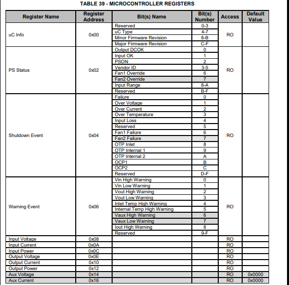
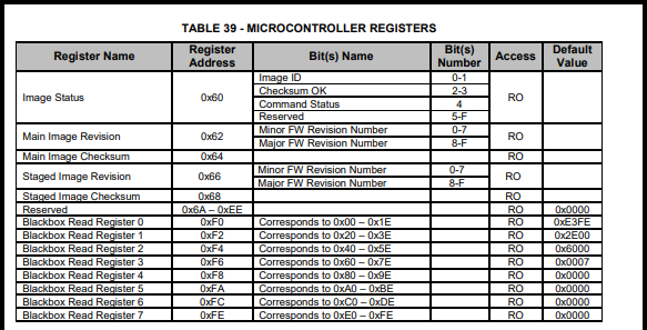
other data can be read in real time. More power data can be read through custom register addresses.
Compatible power supplies: EPW750-12A, PS-2751-7H; other power supplies have not yet been tested.
Due to size and cost limitations, the recommended total power of this power board is no more than 600W.
A copper busbar soldering position (6mm (width) * 50mm (length)) has been reserved.
A forced output shutdown function has been added, which requires Home Assistant. Firmware must be flashed to force IO2 to go high; otherwise, the physical switch will not work. See Figure
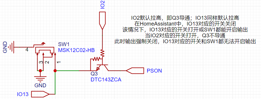
2 for details. Core Board (ATX3.0):
The main circuits of the core board have been windowed.
One PW22ASAB is used for both 5V and 3.3V outputs, and one ZXDN10 is used for 5VSB.
The main control chip is either WT7510 or TPS3510.
III. Postscript:
Because everyone's development environment is different, tutorials on Home Assistant and ESPHOME are not provided. Related tutorials can be found on Bilibili or other platforms.
For firmware flashing of the ESP8266, please prepare a jumper cap and a USB-to-serial adapter module. The silkscreened TX and RX should correspond to the TX and RX of the programmer (the order does not need to be swapped).
IV. PMBUS I2C Address Reference (PS-2751-7H)

V. Reference Images


flash_download_tool_3.9.5_0.zip
esp-12f_product_specification_zh_v1.0_2.pdf
csps_esphome_code (Ver3.0).zip
csps-power-Ver3.0 firmware.bin
Huawei-EPW750-12A-datasheet.pdf
PS-2751-7H-LF Lite-On 750W Platinum Power Supply Datasheet (VDpdf)
NAK12S20(PW22AS)(1).pdf
Power Supply Compartment Model (SFX Bezel).step
BOM_Power Interface Board (ATX3.0) 2024-09-26.xlsx
PDF_CSPS-ATX12VO Smart Power Supply.zip
Altium_CSPS-ATX12VO Smart Power Supply.zip
PADS_CSPS-ATX12VO Smart Power Supply.zip
BOM_CSPS-ATX12VO Smart Power Supply.xlsx
91139
electronic


 京公网安备 11010802033920号

 4306T-101-3480FBL


