* 1. Project Function Introduction
The problem of stringing caused by damp consumables is undoubtedly a source of frustration for every 3D printing enthusiast. The image of strands of ink on a heated bed and the appearance of spiderwebs always evokes deep thought.
Drying ovens and thermometers/hygrometers have become essential tools for every 3D printing enthusiast. (

Figure 1: Never again will I laugh.jpg - a bunch of thermometers/hygrometers)
Traditional drying ovens combining desiccants and sealed boxes can only maintain the moisture level of the consumables; they cannot improve their performance. Over time, the quality of the consumables will still deteriorate.
Using a drying oven with active drying (heating) function can reduce the moisture level of consumables and improve stringing and defects to some extent.
Many drying ovens with active drying functions are available on Taobao, but the prices always make me hesitate. I wonder, do 3D printing enthusiasts' money grow on trees?
Although the price isn't expensive compared to the price of the printer and high-quality consumables, the high price of a simple heating element, controller, and casing is unacceptable to me. (Thinking it's expensive is my problem, private message to Marseille.)
After some internal struggle, I decided not to donate to manufacturers and instead decided to build one myself.
Some DIY solutions modify fruit and vegetable dryers, but the 220V power supply and incompatibility with native consumables deterred me.
This drying component is an addition to a commonly used 5L rice bucket drying box, with minor modifications to achieve temperature and humidity monitoring and active drying functions.
Below is a demonstration of the verified product:
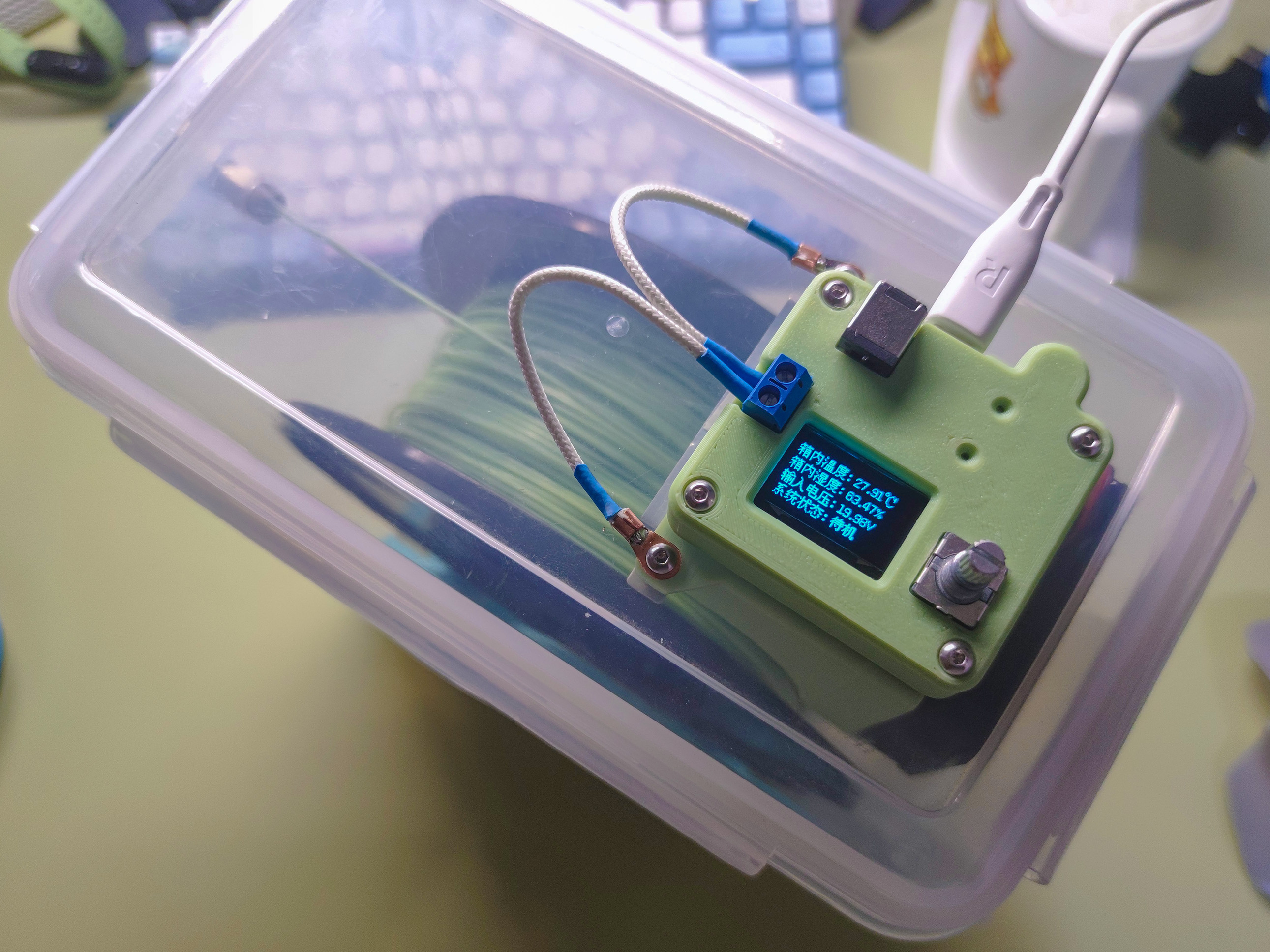
Figure 2: Product Display Figure 1
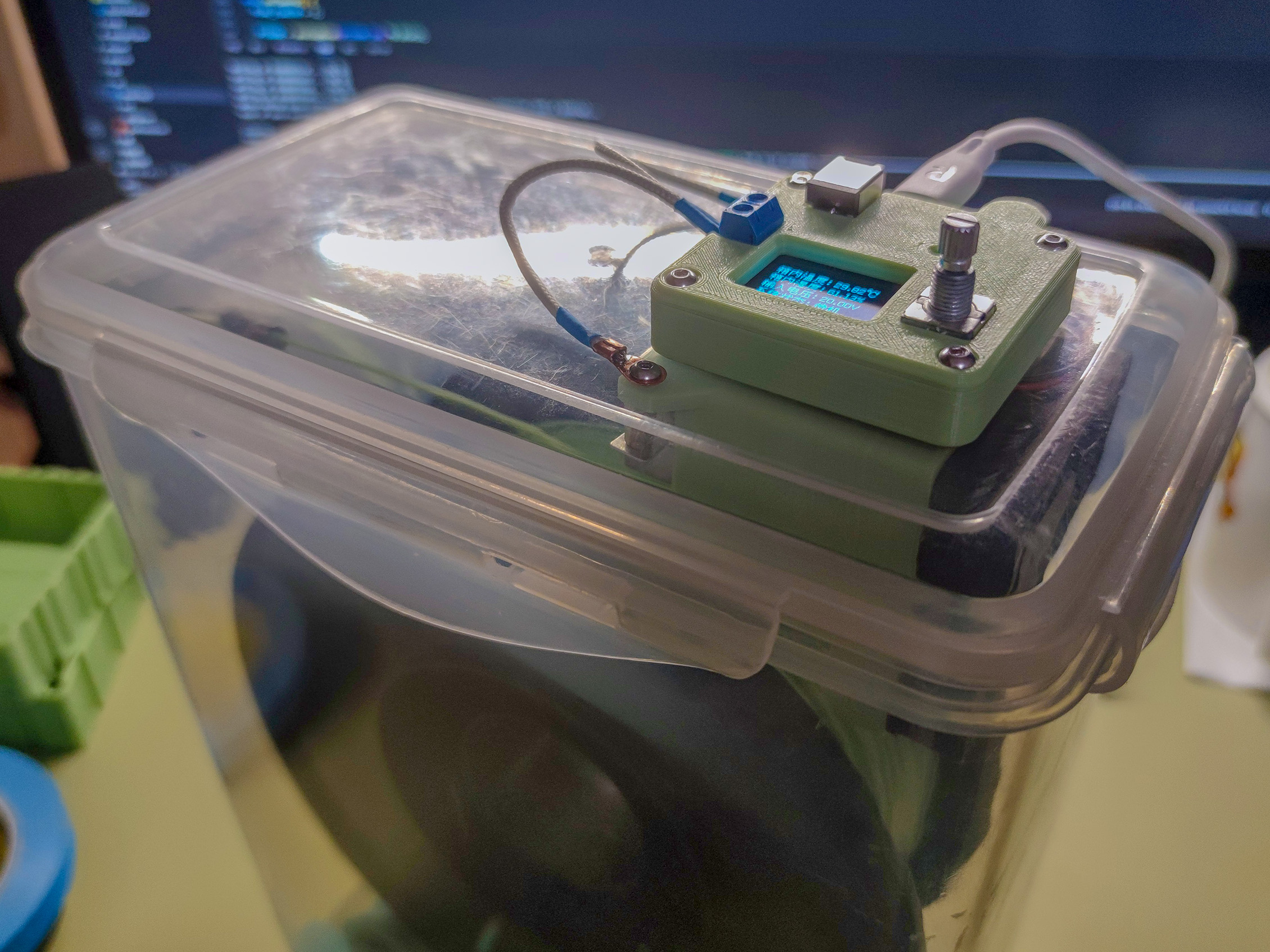
Figure 3: Product Display Figure 2
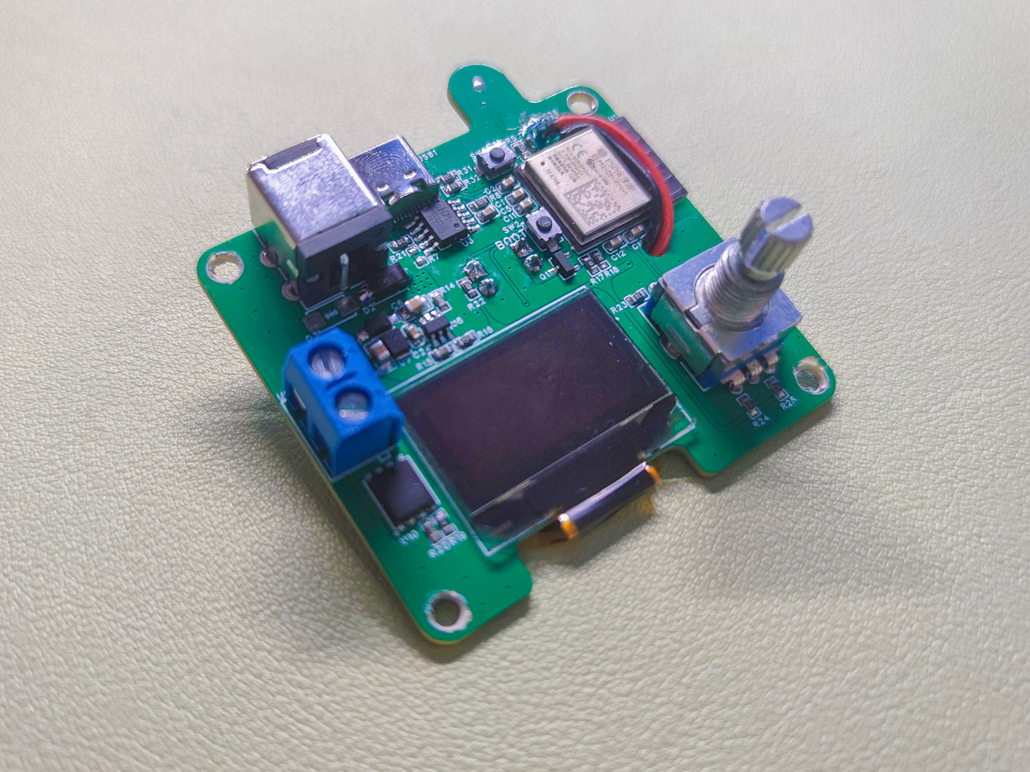
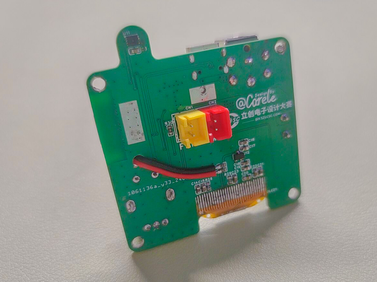
Figure 4: Control Module PCB Display
*2. Project Attributes:
This project is being published for the first time; the project is original; the project has not won any awards in other competitions; the project has not been defended at school.
* 3. Open Source License:
CC BY-NC-SA 4.0
* 4. Hardware Section
4.1 Basic Characteristics
Effective Input Voltage: 10-20V (10V is the software-set undervoltage protection lower limit, which can be changed; 20V is the electrical performance limit of the PTC element)
Drying Temperature Range: 0-255℃ (set by software; answer me, you won't actually heat it to 255℃, right?)
Maximum Design Power: Type-C Input - 60W; DC Input - 80W (output power can be limited by software settings)
Human-Machine Interaction: 0.96 OLED display, EC11 encoder interaction
4.2 System Structure
This component mainly consists of an MCU, power supply section, active drying section, temperature and humidity monitoring, and human-machine interaction section.
The system structure diagram is shown below:
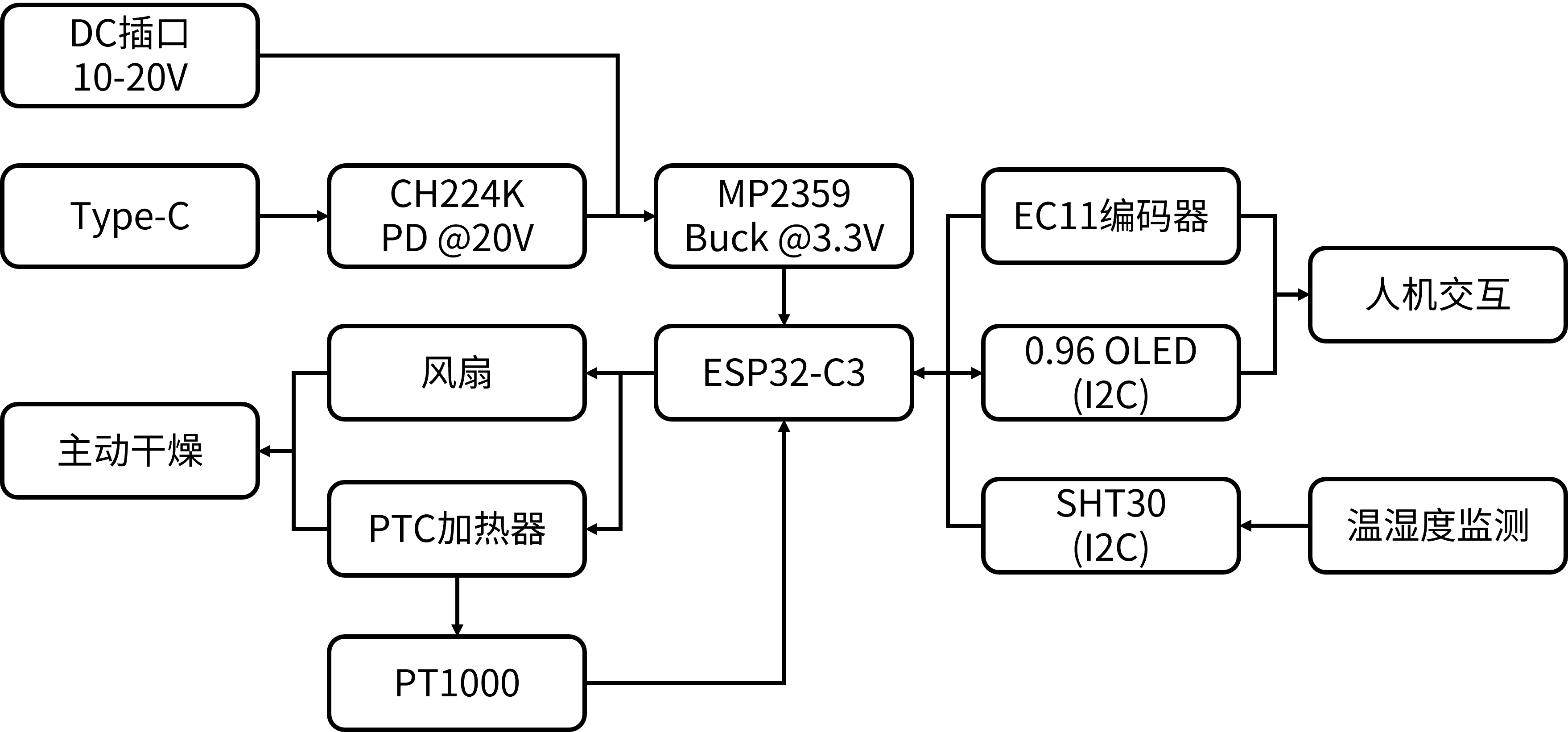
Figure 5 System Structure Diagram
4.3 Hardware Design
· The MCU uses the ESP32-C3-MINI-1-N4 module, which has built-in USB support for JTAG. Everyone who has used it says it's great! This isn't the first time I've used this module in a project, but I always learn something new every time I use it.
The chip has a 12-bit ADC for sampling the PT1000 and input voltage (the drift is significant; it's completely unusable without calibration).
This module has Wi-Fi functionality, and future integration with IoT devices is possible.
Other functions will be described later.
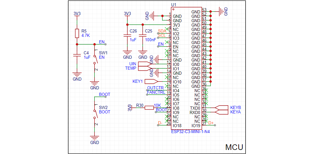
Figure 6 shows the MCU schematic .
For the power supply, the input uses a DC socket + Type-C scheme; the main power supply VBUS directly supplies the PTC heater and fan; the main power supply is stepped down to 3.3V via a DC-DC converter for powering the ESP32-C3, OLED, etc.
A Schottky diode SS54 is connected between the DC socket and VBUS for reverse connection and reverse current protection; a TVS converter is connected to prevent the PTC from being damaged by an input voltage greater than 20V. A CH224K is connected after the Type-C converter for PD spoofing, with Rset set to NC to spoof a 20V voltage.
The DC-DC converter uses a Buck topology and is controlled by an MP2359 chip (available for free from Jiesheng Microelectronics & many Pin2Pin chips). The FB voltage is 0.8V, obtained through resistor division.
The voltage divider resistors were calculated using a genetic algorithm program written in Matlab, iteratively with voltage conditions substituted, with a theoretical error of 0V.
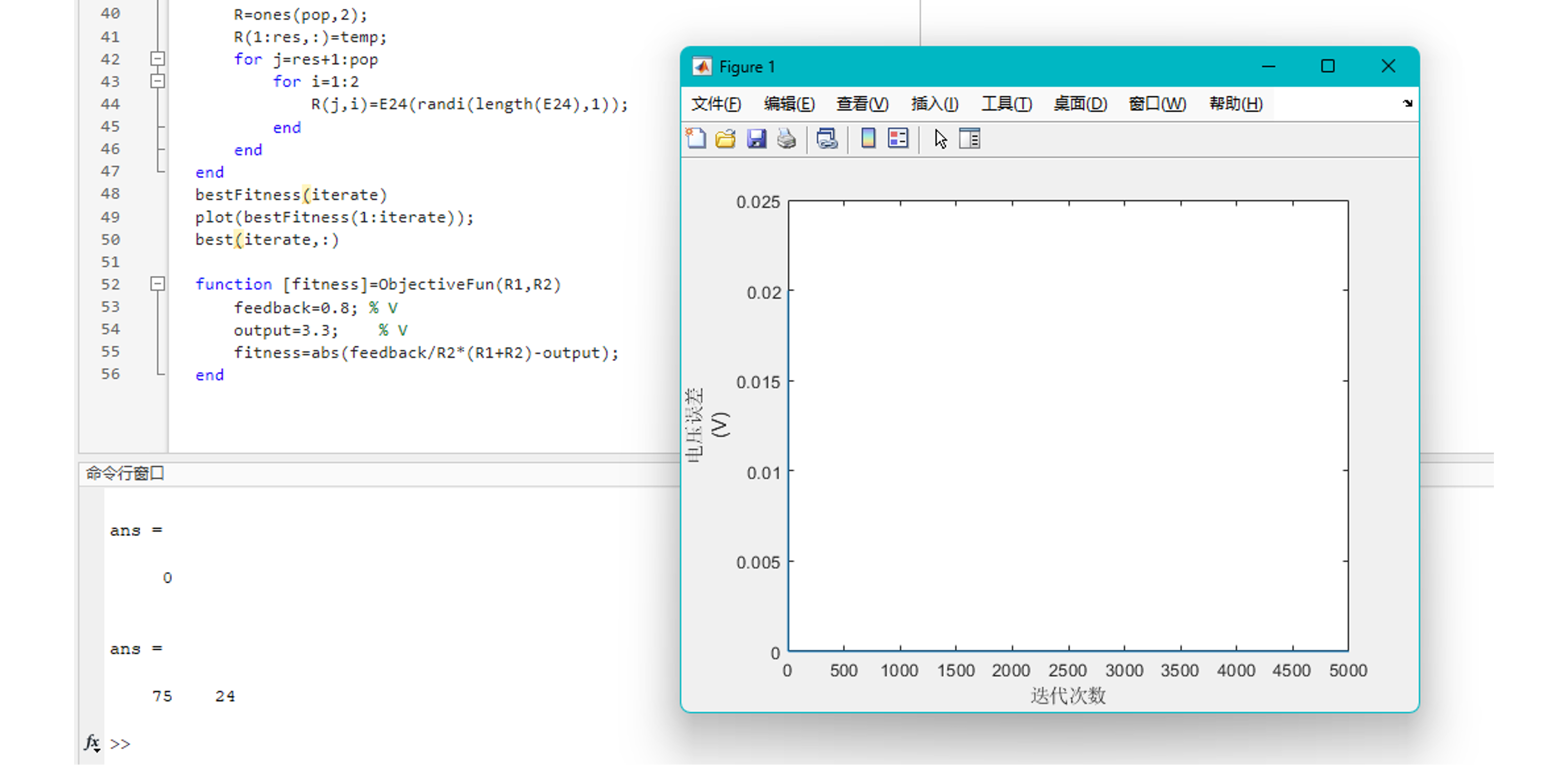
Figure 7 shows the FB resistor calculation
, but note that the output voltage may not be exactly equal to 3.3V, and subsequent ADC calibration requires adjustments to the calibration parameters as needed. (The actual voltage in this project's test was 3.345V, measured using an LCSC530 and a multimeter.)

Figure 8 shows the power supply schematic
. The active drying section consists of PTC heating control, fan control, and PT1000 measurement.
PTC heating control and fan control are implemented using NMOS switching circuits. The fan current is relatively small, so an AO3400 NMOS is used; the PTC requires a larger current, but only a few amps, which can generally be met by a DFN-8 (5x6) packaged NMOS.
The PT1000 measurement involves forming a voltage divider circuit with a 1kΩ resistor, measuring the voltage between the PT1000 and the 1kΩ resistor. (Too lazy to add op-amps for range switching, so I'll just do the software calculation.)

Figure 9
: Schematic diagram of the active drying section. The temperature and humidity monitoring section uses the Sensirion SHT30 temperature and humidity sensor, with data exchange via I2C bus.
The human-machine interface consists of a 0.96" OLED and its driving circuit, and an EC11 encoder.
The OLED selected for this project is the SH1106 128x64 0.96" 30Pin I2C protocol OLED. Generally, 30-pin 0.96" OLEDs are compatible; the EC11 encoder stem height is arbitrary.
The SHT30 and OLED use the same hardware I2C.
In previous designs, two pairs of pins were used, with plans to use two sets of I2C buses. However, during programming, it was difficult to implement Wire1 using library functions (sorry, my coding skills are lacking), so it was changed to use the same pair of pins and the same hardware I2C bus.
Using software I2C for screen access has a significant latency, which will be explained in the subsequent software section.
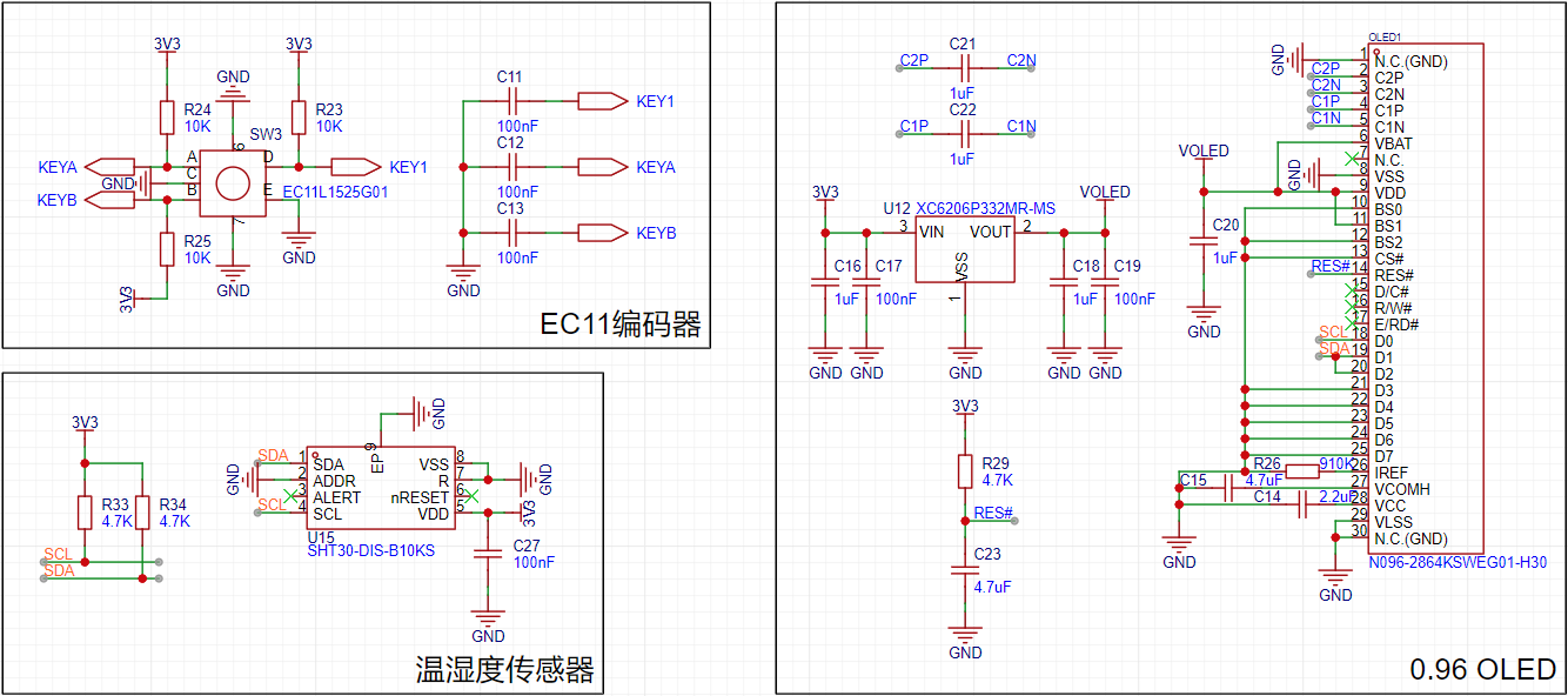
Figure 10: Schematic diagram of temperature and humidity monitoring section & human-computer interaction section
*5. Software Section
5.1 Software Design Ideas
This project is developed based on the Arduino framework, using VSCode PlatformIO as the development environment.
The overall program design is divided into the following parts: display (U8g2), interactive input (Encoder, OneButton), temperature and humidity sensor (Adafruit_SHT31), voltage sampling (analogRead), fan and PTC output control (analogWrite, PID).
Interactive input is implemented by calling library functions in the main loop; display, data sampling, and output control are executed at regular intervals.
5.2 Software Design
The interactive input implementation is relatively simple, achieved by calling functions from the Encoder.h and OneButton.h libraries respectively. Refer to the examples provided by these libraries to implement the corresponding button and encoder functions.
The data sampling and output control consists of two parts: one requiring strict adherence to a constant time interval, and the other requiring a more lenient time interval.
The PT1000 temperature sampling and PTC output control require strict adherence to a constant time interval. This is because this part involves PID control, the detailed principles of which will not be explained in detail here. Other data sampling and fan control do not require strict control.
Therefore, the two types are implemented using different methods. A timer (200ms in the project) is set up, and the part requiring strict time control is placed within the timer. An interrupt flag is also defined; when a timer interrupt occurs, the flag becomes true. In the main loop, an if statement checks the flag and executes the part with a more lenient time interval.
The display is also a more lenient part, and its refresh takes a relatively long time. Therefore, it is placed after the if statement checks the flag.
Initially, it was considered to execute all functions within the timer interrupt service routine, but this resulted in errors and a loop restart (presumably because the service routine had not finished executing when the timer interrupted again, but this was not encountered in the development of ESP32-S3). Therefore, the functions are divided into two parts: strict time interval and lenient time interval, which are executed separately.
5.3 Interaction Logic
The interaction section includes the OLED display and the EC11 encoder input.
• Menu Logic
This project has a two-level menu. The first-level menu displays the current system status (temperature, humidity, input voltage, system status); the second-level menu sets parameters for active drying (heating temperature, heating time, fan and PTC power limits).
In the program design, a boolean variable is used to determine the menu level. Entering each level of the menu, the corresponding item is printed and its value is requested. String() is used to convert the value to a string, which is then concatenated with "+" and displayed in one output.
The second-level menu requires editing specific items, adding a selection option. Therefore, an unsigned char variable is added to store the selected target number, ranging from 0 to 3. When the target number equals the item number, an asterisk (*) is output at the end of the line as a selection marker.
In the second-level menu programming, a structure is used, greatly simplifying the program's complexity (the first-level menu is used as is and I'm too lazy to modify it). The structure stores the item name, unit, value, and adjustment scale.
Using a for loop in conjunction with the struct print statement can greatly compress the program content used for display.
The program is as follows:
struct element{ char* name; char* unit; unsigned char value; unsigned char scale;}; element Setting_Element[] = { {"Heating temperature: ","℃",60,1}, {"Heating time: ","min",0,1}, {"Power limit: ","",32,8}, {"Fan speed: ","",64,8},};
The menu display logic is as follows:
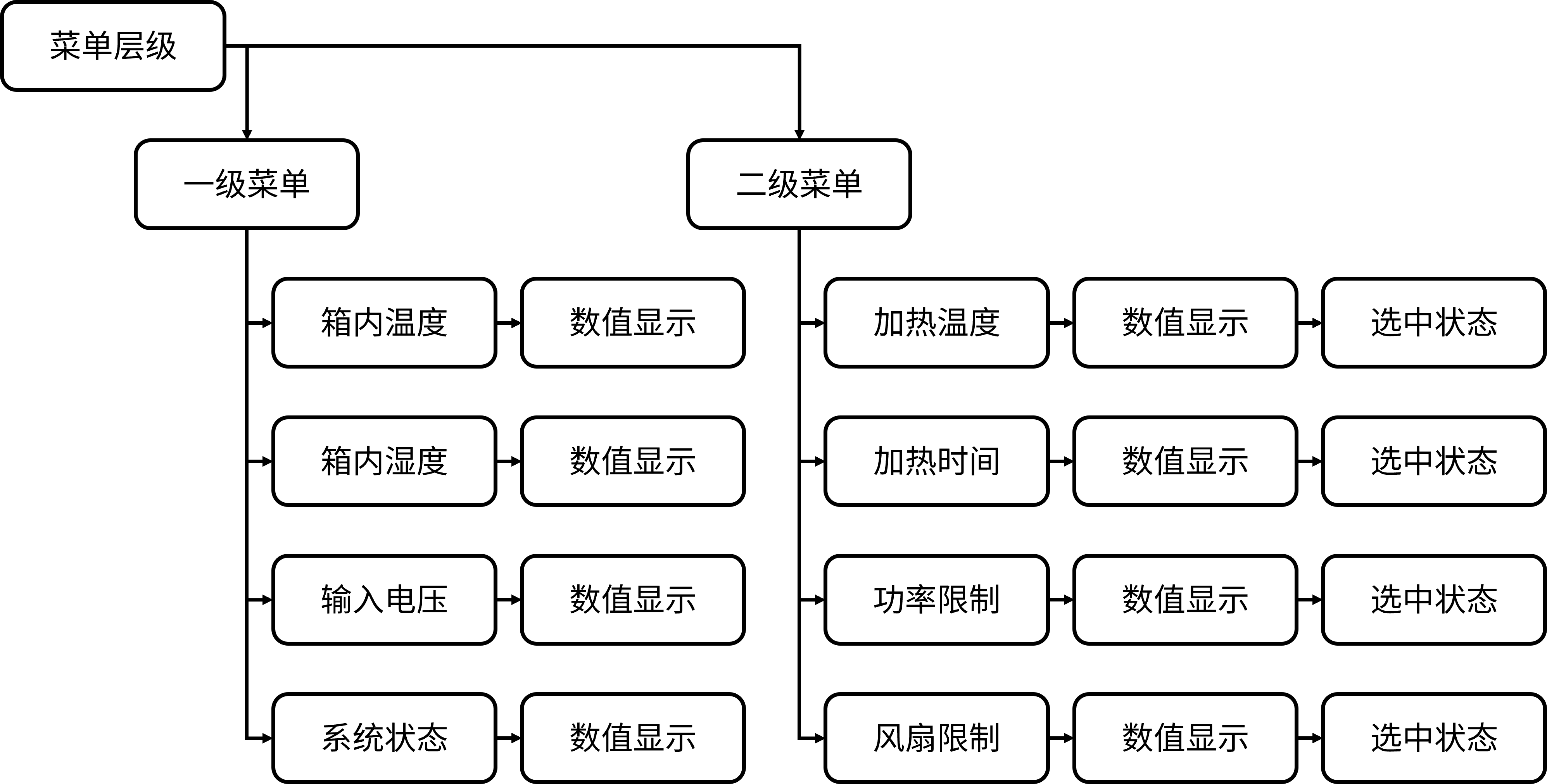
Figure 11 Menu display logic
The menu display effect is as follows:
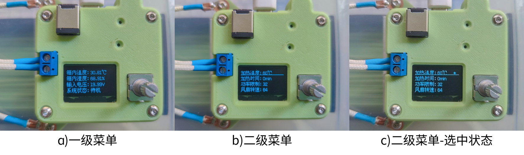
Figure 12 Menu display effect
Input logic
Input is mainly divided into encoder input and button input. The encoder can increase or decrease the value by rotating; the buttons can realize the selection and switching effects through function reuse.
The OneButton library provides a variety of button states. This project only uses two types: single button and long button (because the display time in the main loop is long, double-click recognition is less accurate, so it is discarded).
The Encoder library can record the current encoder position. By comparing the current position with the previous position, it can be determined whether the value has increased or decreased (some jitter still exists in actual use).
The input interaction logic is shown in
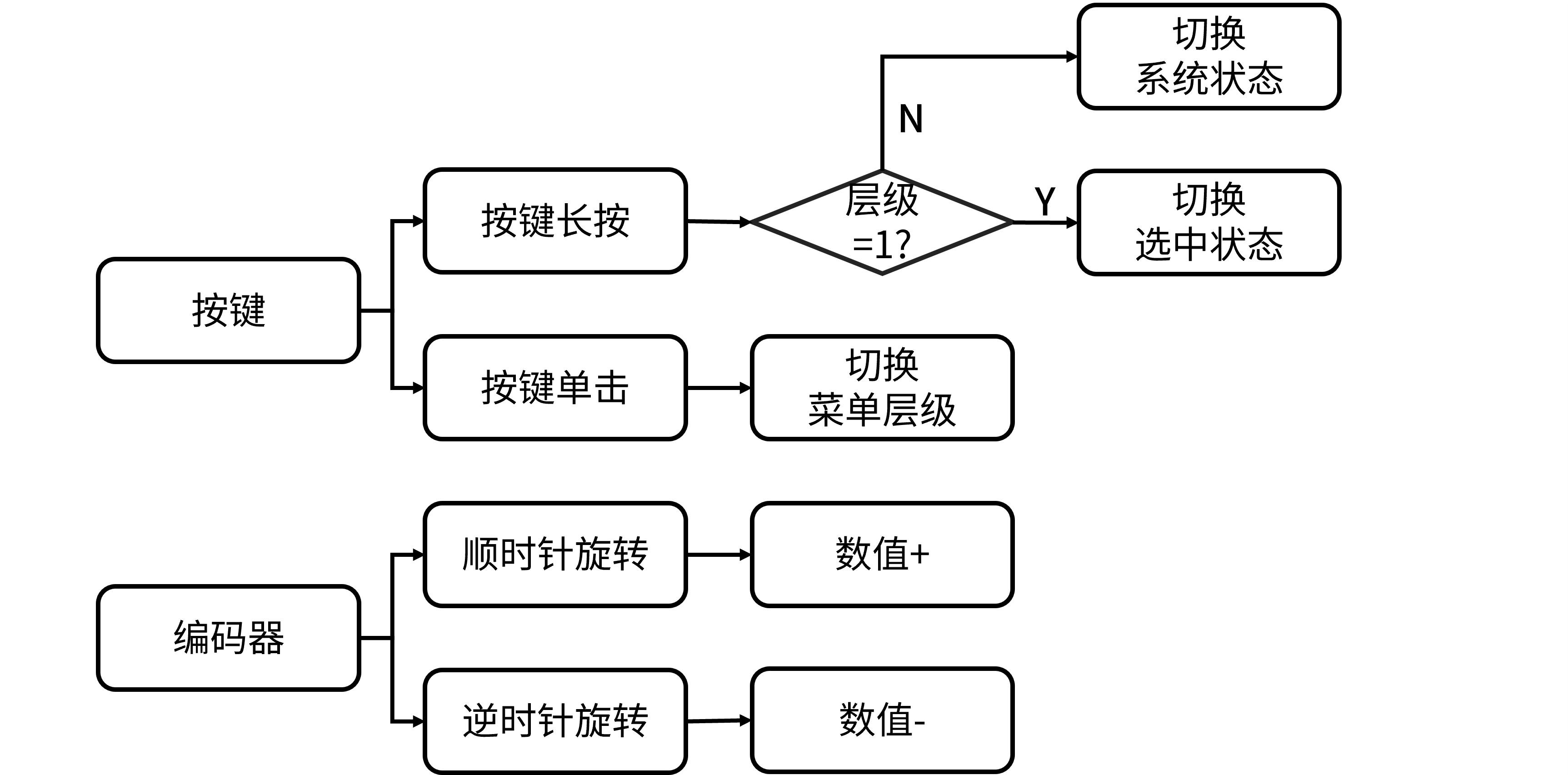
Figure 13.
5.4 Output Control
Output control is divided into two parts: PTC output and fan output. The fan output can be handled simply by calling `analogWrite`; the PTC output requires PID control to maintain a constant output temperature.
The PID control uses incremental PID, that is, adjusting the control value based on the control value at the previous moment. This control method has a relatively small code size (in my opinion).
The PID code is shown below:
// PID float Kp=0.1, Ti=125, Td=5; uint16_t P_Term=0, I_Term=0, D_Term=0;
void PidCtrl(){ // PID term calculation P_Term = Error_Temperature[0] - Error_Temperature[1]; I_Term = Error_Temperature[0]; D_Term = Error_Temperature[0] - 2*Error_Temperature[1] + Error_Temperature[2];
OUT_Status = OUT_Status + Kp*( P_Term + Ts/Ti*I_Term + Td/Ts*D_Term ); // Power limit if(OUT_Status > Setting_Element[2].value){ OUT_Status = Setting_Element[2].value; } analogWrite(OUT,OUT_Status); // Serial.println(String(OUT_Status)+"*"+String(Error_Temperature[0]));
// Temperature error update Error_Temperature[2] = Error_Temperature[1]; Error_Temperature[1] = Error_Temperature[0]; Error_Temperature[0] = Setting_Element[0].value - temperature_PT1000;}
5.5 PT1000 Measurement
The PT1000 is used to measure the temperature of the PTC heater. Unlike the SHT30 temperature measurement, the temperature inside the chamber needs a certain amount of time to rise after heating, which has hysteresis and local temperature differences.
If the SHT30 measurement value is used as the basis for PID control, it may lead to overheating of the PTC, resulting in excessively high temperature near the PTC outlet and melting of consumables. Therefore, an additional temperature sensor is needed to measure the PTC temperature and keep the temperature within a reasonable range.
The resistance of the PT1000 is 1kΩ at 0℃, and the resistance increases with the temperature. However, the relationship is not linear, so it needs to be processed.
Considering that the heating temperature is mostly between 40 and 80℃, this project abandons the measurement accuracy below 40℃ and above 80℃, and adopts a local fitting method to obtain the relationship between temperature and sampled values.
Based on the PT1000 temperature calculation formula, an actual temperature-voltage curve was established. Then, a portion from 40-80℃ was selected and a first-order linear fit was performed using Matlab cftool. The fitting result is shown in

Figure 14.
The green line (local first-order fit) overlaps with the black line (first-order fitting function) in the figure.
However, due to the lack of a tool for temperature calibration, the fitting effect cannot be determined. Furthermore, due to the offset of the ESP32-C3's ADC, the measurement results will inevitably contain some error.
*6. Bill of
Materials (BOM) 6.1 Assembly
List 1 Assembly
List No.
Item
Quantity
Remarks
1
6CM Fan
1
Thickness not limited
2
6x3 Magnets
8
Ensure proper alignment during installation
3
M4x4x5.5 Hex nut
4
4
M4x14 Socket head bolt
4
5
M3x3x4.5 Hex nut
4
6
M3x12 Copper post
1
7
M3x8 Copper post
1
8
M3x4 Flat head screw
2
9
PT1000
1
10
XH2.5 4-2P terminal wire
1
11
PTFE tubing
1
A small section, outer diameter 4mm (Those who play with 3D printing probably have this, right?)
12
M3x10 Screws
2
Round head or flat head
13
M3x8 Screws
4
Countersunk head is best
14
Copper lugs
2
Hole inner diameter >3mm
15
PTC heater
1
12V 50W
16
Controller module
1
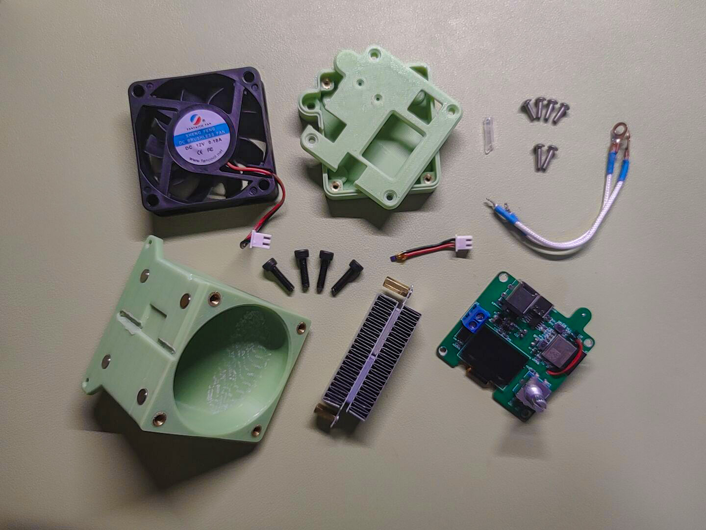
17. One printed part
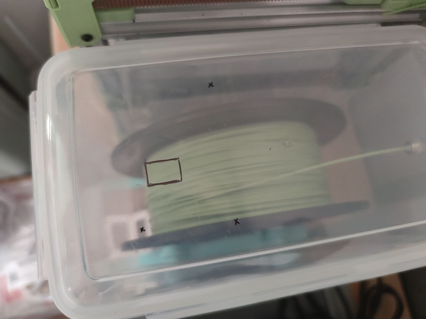
of the nozzle , see attachment 18. One printed part of the controller base , see attachment 19. One printed part of the controller cover , see attachment Figure 15 Module composition display 6.2 Module assembly diagram 16 Assembly exploded view (partial) During installation, the 5L rice bucket needs to be drilled. Two holes are for PTC heater terminals, one is for PTFE tube extension holes, and a square hole is for extending the XH socket and terminal wires. As shown in the following figure: Figure 17 Drilling marks *7. Competition LOGO verification Figure 18 Competition LOGO verification *8. Demonstrate your project and record it as a video . Upload the video. See attachment. 8.1 Additional notes on the project During the physical verification process, some unreasonable aspects were found. It is not recommended to directly replicate this project. It is suggested to make certain modifications before replicating. The following are the points to be improved: 1. Fan noise. The fan control uses analoagWrite, which has a low PWM frequency and produces a lot of noise during operation. It is planned to try to change it to ESP32's ledc control. 2. Fan connection with PT1000. 1. The current XH connector placement is inconvenient, requiring tweezers for assembly. The socket should be placed on the side for easier connection; alternatively, a secondary board could be added, or the PogoPin could be replaced to achieve plug-free connection and reduce the possibility of air leakage. 2. The screen refresh rate is low. The current solution uses hardware I2C, which is a significant improvement over the original software I2C, but the refresh time is still relatively long, leaving considerable room for improvement. (This can also be optimized in the code, but my software skills are limited.) 3. Temperature and humidity are not linked to active drying. Currently, no linkage has been implemented, such as setting a humidity threshold for active drying. 4. Desiccant placement. The original plan was to magnetically attach the desiccant to the other side of the fan, but the space was too small during actual installation. This project is merely intended to spark discussion and provide some design ideas for reference by experts. Appendix Appendix 1 Project Program #include #include #include #include #include "Adafruit_SHT31.h" #define ENCODER_OPTIMIZE_INTERRUPTS #include #include "OneButton.h" // IO Setting#define OUT 4#define FAN 5#define UIN_IN 0#define PT1000_IN 1

// Variable Definition float temperature = 0; // Temperature inside the chamber float humidity = 0; // Humidity inside the chamber uint16_t UIN = 0; // UIN reading uint16_t PT1000 = 0; // PT1000 reading float voltage_UIN = 0; // UIN voltage float temperature_PT1000 = 0; // PT1000 temperature unsigned char OUT_Status = 0; // PTC output status float Error_Temperature[3] = {0}; // Temperature error queue const uint16_t Ts = 200; // Sampling, uploading, and control cycle settings bool FLAG_timIT0 = 0; // timer0 interrupt flag bool System_Status = 0; // System status 0 - Standby; 1 - Heating bool List_Level = 0; // Menu level 0 - Home; 1 - Settings bool Choose_Status = 0; // Selected status bool UIN_Error = 0; // Low input voltage flag unsigned char UIN_threshold = 10; // Voltage threshold unsigned char Choose_Targrt = 0; // Selected target uint16_t heating_times = 0; // Heating time counter uint16_t heating_sum_time = 0; // Maximum value of heating counter
struct element{ char* name; char* unit; unsigned char value; unsigned char scale;}; element Setting_Element[] = { {"Heating temperature: ","℃",60,1}, {"Heating time: ","min",0,1}, {"Power limit: ","",32,8}, {"Fan speed: ","",64,8},};
// U8G2#define SDA 7#define SCL 6// U8G2_SH1106_128X64_NONAME_F_SW_I2C //
SHT30Adafruit_SHT31 sht31 = Adafruit_SHT31();#define SHT30_SDA 2#define SHT30_SCL 3
// Encoder#define KeyA 20#define KeyB 21Encoder Enc(KeyB, KeyA);long oldPosition=-999;long newPosition=0;
void EncoderRead(){ if(Enc.read() != oldPosition) { newPosition = Enc.read(); Serial.println(newPosition); if(List_Level){ if(Choose_Status){ if(newPosition>oldPosition){ Setting_Element[Choose_Targrt].value+=Setting_Element[Choose_Targrt].scale; } else{ Setting_Element[Choose_Targrt].value-=Setting_Element[Choose_Targrt].scale; } } else{ if(newPosition>oldPosition){ Choose_Targrt+=1; } else{ Choose_Targrt-=1; } if(Choose_Targrt>3){ Choose_Targrt=0; } } } oldPosition=newPosition; }}
// OneButton#define Key1 10OneButton button(Key1, true);
// Key click void Click1() { Serial.println("click"); List_Level = !List_Level; Choose_Status = 0; Serial.println(List_Level);} // Long press void longPressStart() { Serial.println("longPressStart"); if(!List_Level){ if(1){//voltage_UIN > UIN_threshold){ System_Status = !System_Status; heating_times = 0; heating_sum_time = Setting_Element[1].value *300; } else{ UIN_Error = 1; } } else{ Choose_Status = !Choose_Status; }}
// Data reading void dataRead() { temperature = sht31.readTemperature(); humidity = sht31.readHumidity(); UIN = analogRead(UIN_IN); voltage_UIN = UIN*0.006046; // 1/4096*3.3*8.5 Depends on the ESP32-C3 coefficients and needs to be calibrated manually. // PT1000 = analogRead(PT1000_IN);}
// PIDfloat Kp=0.1, Ti=125, Td=5;uint16_t P_Term=0, I_Term=0, D_Term=0;
void PidCtrl(){ // PID term calculation P_Term = Error_Temperature[0] - Error_Temperature[1]; I_Term = Error_Temperature[0]; D_Term = Error_Temperature[0] - 2*Error_Temperature[1] + Error_Temperature[2];
OUT_Status = OUT_Status + Kp*( P_Term + Ts/Ti*I_Term + Td/Ts*D_Term ); // Power limit if(OUT_Status > Setting_Element[2].value){ OUT_Status = Setting_Element[2].value; } analogWrite(OUT,OUT_Status); // Serial.println(String(OUT_Status)+"*"+String(Error_Temperature[0]));
// Temperature error update Error_Temperature[2] = Error_Temperature[1]; Error_Temperature[1] = Error_Temperature[0]; Error_Temperature[0] = Setting_Element[0].value - temperature_PT1000;}
// Timer setting hw_timer_t *timer0 = NULL; // Timer 0 sampling, uploading, and control refresh // Status update void onTimer0() { FLAG_timIT0 = 1;
PT1000 = analogRead(PT1000_IN) *0.85+52; temperature_PT1000 = (PT1000-2070)/3.11; // Serial.println(temperature_PT1000);
heating_times++; if(System_Status){ PidCtrl();
if(heating_times >= heating_sum_time){ System_Status = 0; heating_times = 0; Setting_Element[2].value = 0; } } // Serial.println(PT1000); // Serial.println(temperature_PT1000); }
unsigned char ITtimes=0; // Counter for screen refresh
void setup() { // put your setup code here, to run once: // IO Setting pinMode(OUT,OUTPUT); pinMode(FAN,OUTPUT); pinMode(PT1000_IN,INPUT); pinMode(UIN_IN,INPUT);
// Serial Serial.begin(115200);
// SHT30 Wire.begin(SHT30_SDA,SHT30_SCL); if (!sht31.begin(0x44)) { while (1) { Serial.println("SHT31 sensor not found!"); } }
// U8G2 u8g2.begin(); u8g2.enableUTF8Print(); u8g2.setFont(u8g2_font_wqy14_t_gb2312a);
button.reset();//Clear the button state machine button.attachClick(Click1); button.attachLongPressStart(longPressStart);
// Timer initialization // Timer 0 timer0 = timerBegin(0,80,true); // Initialize timer - use timer 1 timerAttachInterrupt(timer0,onTimer0,true); // Bind timer interrupt service function timerAlarmWrite(timer0,Ts*1000,true); // Set interrupt interval to sampling period timerAlarmEnable(timer0); // Start timer }
void loop() { // put your main code here, to run repeatedly: EncoderRead(); button.tick();
if(FLAG_timIT0){ FLAG_timIT0 = 0;
dataRead(); if(System_Status){ analogWrite(FAN,Setting_Element[3].value); } else{ analogWrite(FAN,0); analogWrite(OUT,0); } ITtimes++; if(!List_Level){ if(ITtimes >= 4){ ITtimes = 0;
u8g2.clearBuffer(); u8g2.setCursor(0, 15); u8g2.print("Indoor temperature: "+String(temperature)+"℃"); u8g2.setCursor(0, 31); u8g2.print("Indoor humidity: "+String(humidity)+"%"); u8g2.setCursor(0, 47); u8g2.print("Input voltage: "+String(voltage_UIN)+"V"); u8g2.setCursor(0, 63); if(UIN_Error){ u8g2.print("System status: Voltage too low"); u8g2.drawHLine(0, 63, 128); } else{ if(System_Status){ u8g2.print("System status: Heating"); } else{ u8g2.print("System status: Standby"); } } u8g2.sendBuffer(); } } else{ if(ITtimes >= 1){ ITtimes = 0;
u8g2.clearBuffer(); for(unsigned char i=0; i u8g2.setCursor(0, (i+1)*16-1); u8g2.print(Setting_Element[i].name+String(Setting_Element[i].value)+Setting_Element[i].unit); if(Choose_Targrt == i){ if(Choose_Status){ u8g2.setCursor(112, (i+1)*16-1); u8g2.print("*"); } u8g2.drawHLine(0, (i+1)*16-1, 128); } } u8g2.sendBuffer(); } } }}


 京公网安备 11010802033920号

 127-1-1370-6006-32


