I. Project Introduction
I noticed that the production costs of open-source heating platforms on the platform are relatively high. Therefore, my graduation project is a comprehensive design based on existing open-source solutions, with added features, to realize a low-cost intelligent temperature-controlled heating platform.
II. Open Source License
CC BY-NC
III. Project-Related Functions
1. Automatic Sleep Protection
2. Constant Temperature Adjustable, Temperature Data is Not Lost When Power Off
3. Air Cooling
4. Beep Alarm
5. Diverse Human-Computer Interactions IV.
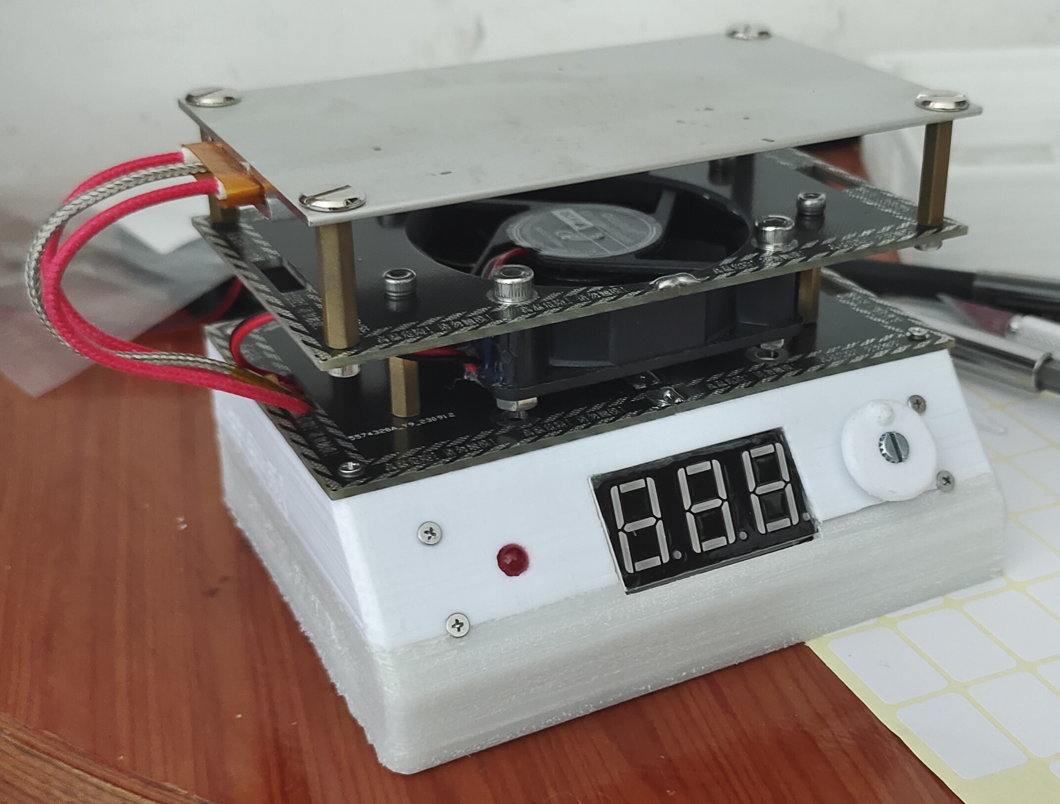
Physical Demonstration
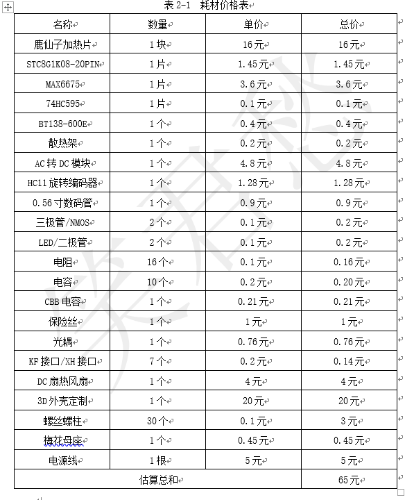
V. Price Estimate Table
VI. Hardware Design Principles
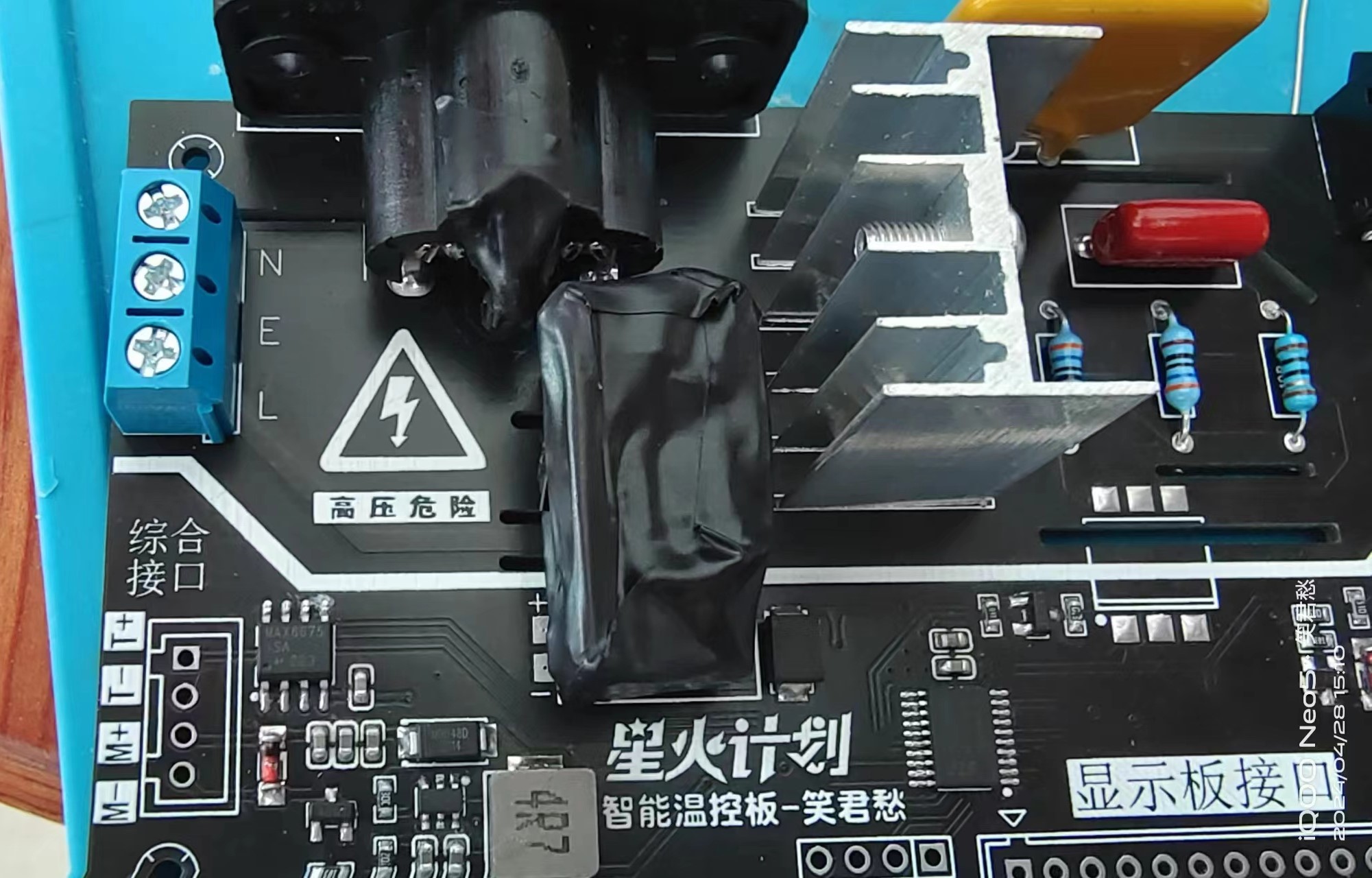
As shown in the hardware logic diagram below, the hardware mainly consists of the following 7 parts
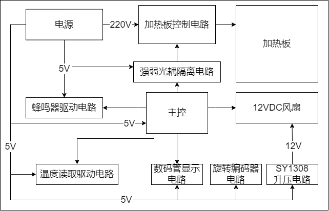
: 1. Power Supply Circuit:
Responsible for the power control and management of the entire product. For example, the low-voltage part requires +5V and +12V power, while the high-voltage part requires 220V high-voltage power, which requires strong and weak voltage isolation management. 2. Heating Plate Control Circuit and Strong/Weak Optical Coupling Isolation Circuit:
The switching control of the heating plate uses a thyristor BT138-800E and an optocoupler MOC3041 for control and strong/weak voltage isolation! 3. Main Control Circuit:
An STC8G1K08-20P chip is used as the main control, offering excellent value for money!
4. Temperature Reading Drive Circuit:
Higher temperature reading accuracy increases cost and technical difficulty. Considering cost, the MAX6675 chip is used for high-precision temperature acquisition. This chip has high integration and eliminates the need for external amplifier circuits, maximizing hardware stability. 5. Data Temperature Display Circuit and Rotary Encoder Circuit:
To provide a good user experience, interactive display of the detected and set temperatures is required. Therefore, a common cathode 0.56mm digital tube with a 3-digit display is used, and an EC11 rotary encoder is used for interaction.
6. Cooling Circuit:
Because the heating platform is a high-temperature product, considering the safety of the equipment after use, an innovative "air-cooling reminder" design is adopted. When the heating platform needs to be turned off, the fan is turned on for cooling. If the safe temperature is reached, a buzzer reminds the user to shut down!
VII. Software Programming Logic Description (
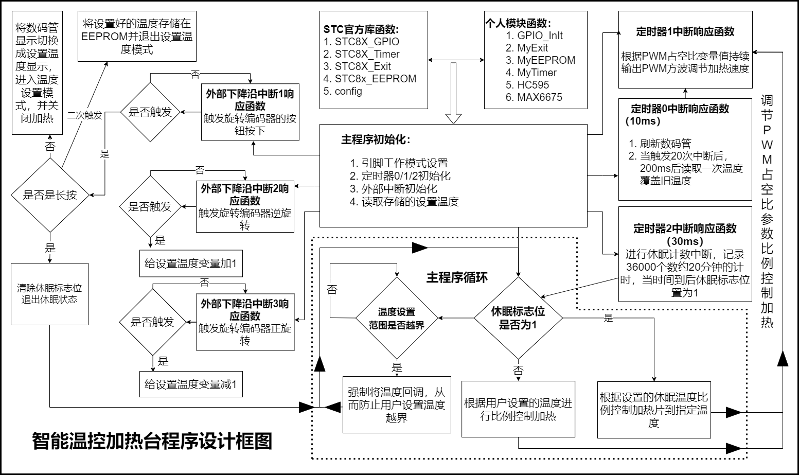
as shown in the diagram): The overall program design is based on official library functions and register-based development, combined with various custom function designs such as: 1. GPIO initialization function: sets the function of specified GPIO pins. 2. External interrupt initialization function: sets the default data for external interrupts and enables interrupts for triggering the rotary encoder. 3. EEPROM storage initialization function: stores and reads the set temperature to ensure the temperature setting is retained even when power is off. 4. Timer 0/1/2 initialization function: sets the timer size and enables interrupts, running the specified program during interrupts. Initialization functions include the digital tube display function and the temperature reading function. 5. The main program performs power-on initialization. The main loop only controls the proportional heating of the heating element and monitors and locks the set temperature range. Time-consuming multiple threads such as rotary encoder reading, digital tube scanning, temperature reading, and sleep counting are executed by the corresponding interrupt response functions, ensuring stable program operation. ...See the pictures for details. Typing all this by hand is tiring.
VIII. Production Tutorial
1. Board Soldering:
(1) Solder the control board and power board according to the soldering diagram! (The assembly and soldering diagram is in the project.) Pay attention to the burning issue! If there is no 5V power supply, you need to burn it first. Only solder the main control chip, filter capacitor and burning header, as shown in the figure! Otherwise, it will be difficult to burn later. Refer to the burning tutorial below!

(2) Cut the wiring terminals: Here you need to cut 16 wire wiring terminals. Of course, if you are too lazy to cut them, you can buy ready-made ones, XH2.54 12P. However, the fan and thermocouple ports must be cut by hand!
(3) High voltage treatment: There is a grounding wire here. Of course, you can choose not to solder it. If you solder it, you must pay attention to wrapping the plum blossom female and the power module with electrical tape for insulation! As shown in the figure! Even if you don't ground it, you can still do some insulation treatment for safety!
(4) Program burning: See the burning tutorial above! After burning, connect the corresponding parts! Observe that there is no obvious short circuit phenomenon, and then power on to test! Princes and princesses, please be careful!
2. Programming:
As shown in the figure, before programming the chip, you need to pay attention to some settings: Select STC8G1K08-20P/16PIN for the chip; Set the main frequency to 24M; Uncheck the download and erase EEPROM. After setting, connect according to the wiring diagram and you can program! Note! Because the power-on current of this board is relatively large, it will cause the serial port to be lost. Therefore, you need to use a backup power supply for programming, or program the chip before soldering is completed! The programming method is the same as STC89C52, cold start programming, but you need to configure it! As shown in the figure

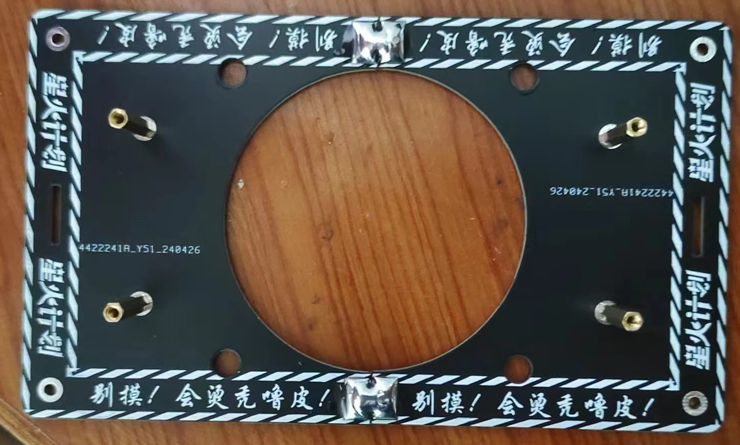
3. Housing installation:
(1) Now use M2*12 screws to directly screw onto the board and apply hot melt glue to fix it (anything that can fix it is fine). Then remove the screws!

(2) Then install the M2*12 screws into the holes on the slant, and first install the M2*6 copper pillars directly! Do not install it completely, leave some protrusions and then align the prepared display board with nuts and install it. Be careful not to tighten the screws too much! After installing the display board, install the control board. You can first install the screws on the socket and then install the control board fixing screws. Then connect the various interfaces!
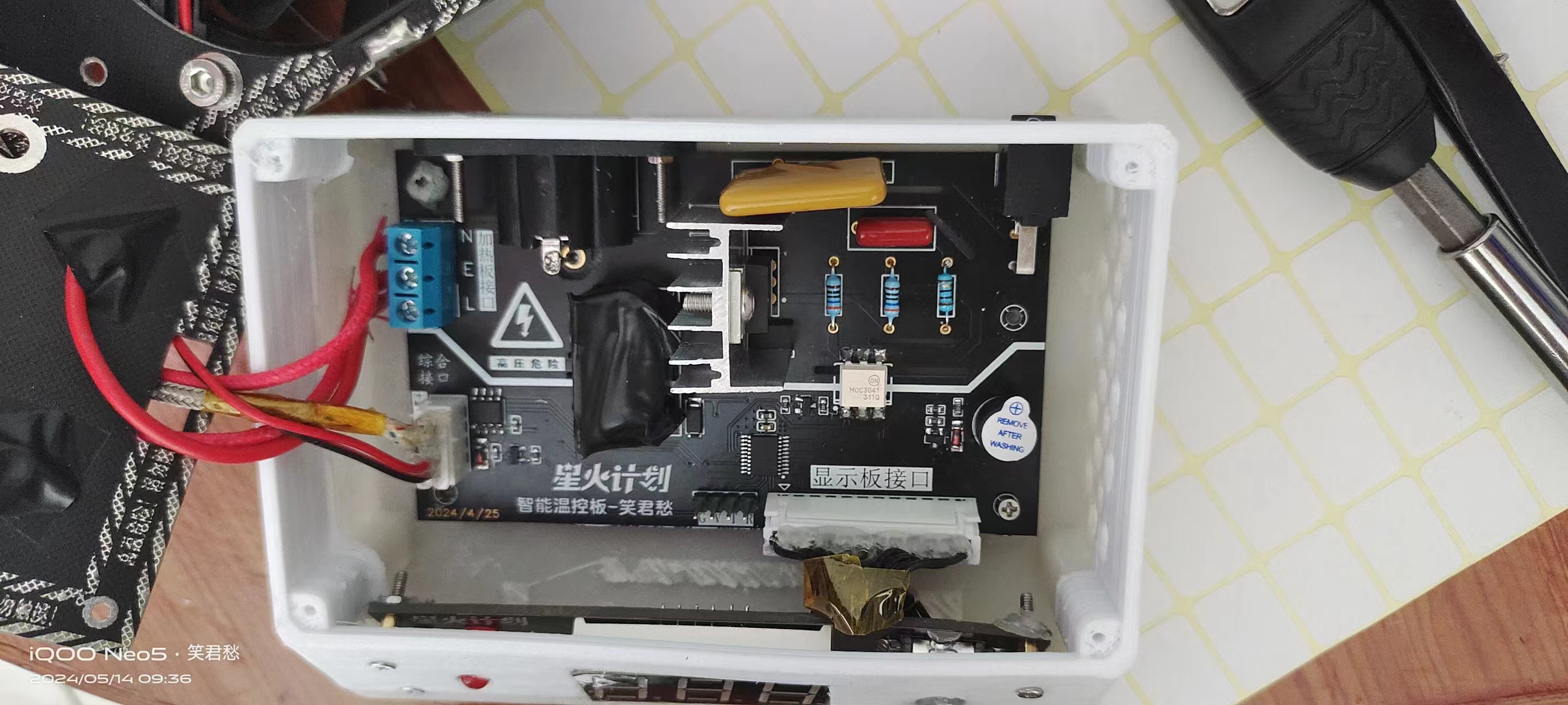
(3) Hardware connection is shown in the figure: (If grounding is required, just use a thick wire to connect the cover plate screws)

(4) After installation, install the cover plate and the heat insulation plate. (The cover plate is available in 3D printed and PCB versions, depending on your needs). As for the installation of the cover plate, you will basically know how to do it once you get it.
Finally---done? ......How could that be..... Make sure there are no problems with the installation and that there are no missing screws inside. Power on! Be careful, princesses and princes, it might bang...
IX. Summary of problems (If all else fails, a good night's sleep might fix it):
1. Why does the program burning fail and the serial port disconnect?
Answer: Refer to the program burning section for prompts!
2. Why doesn't the board heat up?
Answers: 1. Check if the MAX6675 chip is soldered correctly, then use a buzzer to check if it's connected to the interface, or check if the heating plate interface is installed correctly.
2. Still can't do it after reading the tutorial?
Answer: Take a look at the general idea. If you still don't understand too much, I'll make a video tutorial!
3. Encountered a certain bug:
Answer: "Rebooting the Cooling Method" Because this project has added too many functions, there may be bugs during use. I have fixed all the bugs I encountered. If you encounter any bugs, you can record them and report them to me.
Note: This project is for learning purposes only and commercial use is prohibited! Cooperation is welcome!
X. How to use:
1. After long-pressing to enter the temperature setting interface, click the knob once, then rotate it left or right to adjust the temperature range from 30-250 degrees! Long-press again to exit the setting interface! The temperature setting is complete.
2. Double-clicking can turn on the fan for cooling. Note: Manually turning on the fan will not heat up!
3. A single click initiates sleep/wake mode. I've set it to automatically sleep for approximately 30 minutes! Automatic sleep: If no click is made within 30 minutes of operation, it will enter standby mode at 100 degrees Celsius!
(Feel free to ask questions in the discussion group; I'll reply when I have time!)


 京公网安备 11010802033920号

 M245FAN


