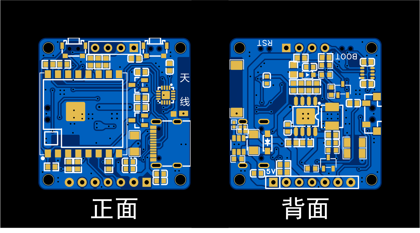
 the PCB plan of the mid-layer control board V1.1
  are shown. Regarding the soldering method for the mid-layer control board, Zhang proposed a new approach: using Sn42Bi57Ag1 low-temperature solder paste with a melting temperature of approximately 148 degrees Celsius. First, solder all components on the front side of the PCB (the side where the ESP07S module is located). Then, apply solder paste to the back side and place all components there. Since the ESP07S module and Type-C interface on the front side of the PCB are at the same height, the soldered PCB can be placed face down on the heating platform for soldering the back side. When removing the PCB after soldering the back side, it must be done carefully and perpendicular to the heating platform. Do not shake it excessively during removal, otherwise components may shift or fall off. This method requires a high degree of precision in the soldering process and necessitates the use of a stencil for solder application. However, the soldering process is simpler and requires fewer tools and equipment. Regarding the control of the heating table temperature during soldering, for Sn42Bi57Ag1 low-temperature solder paste, when soldering the front side of the PCB, first stabilize the heating table temperature at 170 degrees Celsius, then place the PCB on it and solder the front side. Simultaneously, adjust the heating table to 200 degrees Celsius. When it reaches 200 degrees Celsius, remove the circuit board; the front side of the PCB is now soldered. For the back side of the PCB, first stabilize the heating table temperature at 180 degrees Celsius, place the PCB face down on the heating table, and then heat to 220 degrees Celsius until the solder paste on the back of the PCB melts. Then, remove the PCB vertically; the soldering is complete. This soldering method has been tested and, apart from being slightly slower, it generally does not result in component damage.
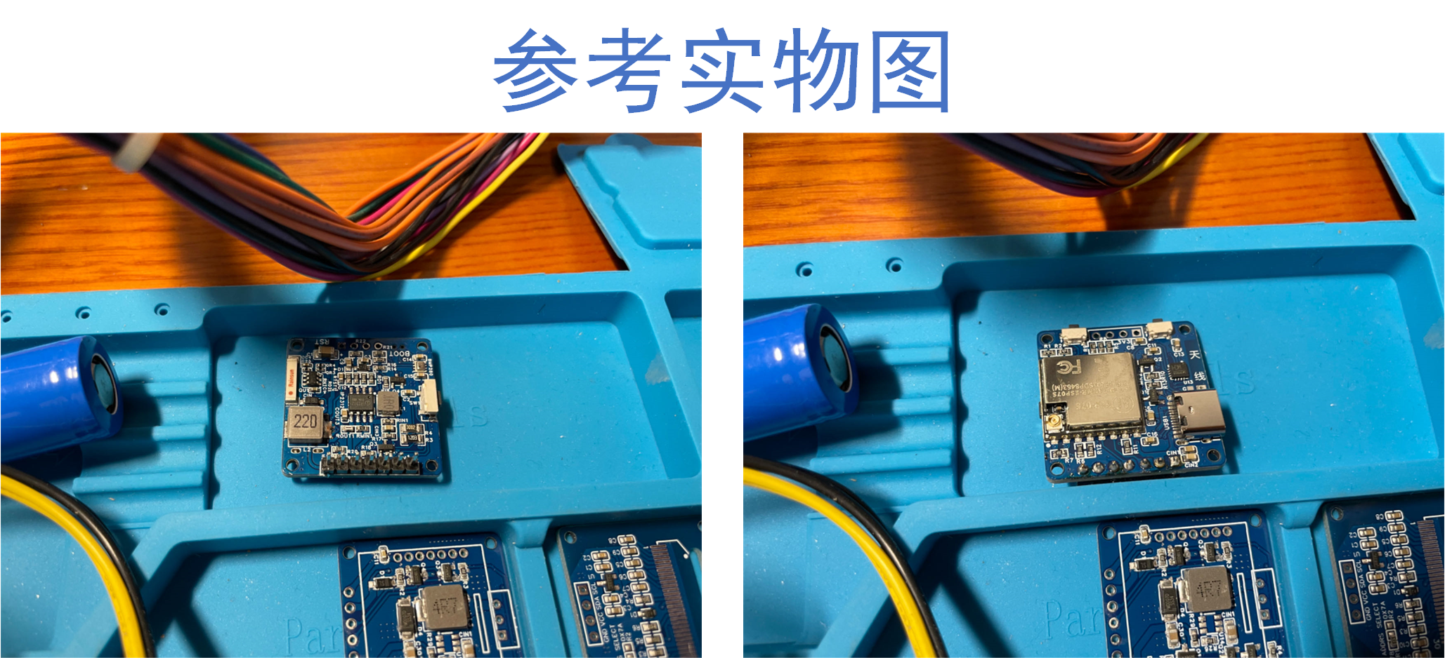
 , please refer to the soldering guide in "Multi-parameter Miniature Environmental Quality Detector Based on ESP07S". The recommended soldering order is as follows: first, use a heating plate to solder all components on the front of the PCB, then use a soldering iron or hot air gun to solder the two capacitors on the back. Note that if the middle control board is version V1.1, the overall thickness of the middle control board increases because the L2 inductor on the back of the V1.1 middle control board has been changed from a 1206L package to an L0630 package. This requires the battery size on the back of the bottom power board to be modified to 802025 to be compatible with the V1.1 middle control board.


All reference designs on this site are sourced from major semiconductor manufacturers or collected online for learning and research. The copyright belongs to the semiconductor manufacturer or the original author. If you believe that the reference design of this site infringes upon your relevant rights and interests, please send us a rights notice. As a neutral platform service provider, we will take measures to delete the relevant content in accordance with relevant laws after receiving the relevant notice from the rights holder. Please send relevant notifications to email: bbs_service@eeworld.com.cn.
It is your responsibility to test the circuit yourself and determine its suitability for you. EEWorld will not be liable for direct, indirect, special, incidental, consequential or punitive damages arising from any cause or anything connected to any reference design used.
Supported by EEWorld Datasheet
EEWorld
subscription
account

EEWorld
service
account

Automotive
development
community

Robot
development
community

About Us Customer Service Contact Information Datasheet Sitemap LatestNews


Room 1530, 15th Floor, Building B,
No.18 Zhongguancun Street,
Haidian District,
Beijing, Postal Code: 100190
China
Telephone: 008610 8235 0740
 京公网安备 11010802033920号

 1CS208-49TT


