I. Project Introduction This project
uses the ESP32-S3N8R8 module as the main control chip. The S3 core adds instructions for accelerating neural network calculations and signal processing, enabling us to quickly parse trained speech models for speech recognition.
II. Principle Analysis
This project consists of four parts: power supply, LED lighting, main control, and speech recognition extension. The main function is to receive and process speech signals through a microphone, extract human voice data, analyze and compare it, and perform corresponding control operations when the sound matches the instructions.
2.1 Power Supply Circuit
A TYPE-C-16P interface is used as the power supply interface. The corresponding USB data pins are connected to the corresponding USB pins on the S3 (USBD+ IO20) and (USBD- IO19), allowing direct USB download and debugging without conversion to serial signals. 5.1K pull-down resistors are added to the CC1 and CC2 pins for easy identification and configuration by different hosts.

The AMS1117 is used as a 5V to 3.3V step-down LDO. The ESP32S3 consumes a significant amount of current when enabling wireless RF or performing voice analysis calculations. Considering the presence of other peripheral circuits, a power supply chip with an output current of at least 600mA was selected. The AMS1117, with an output current of 1A, meets this requirement.

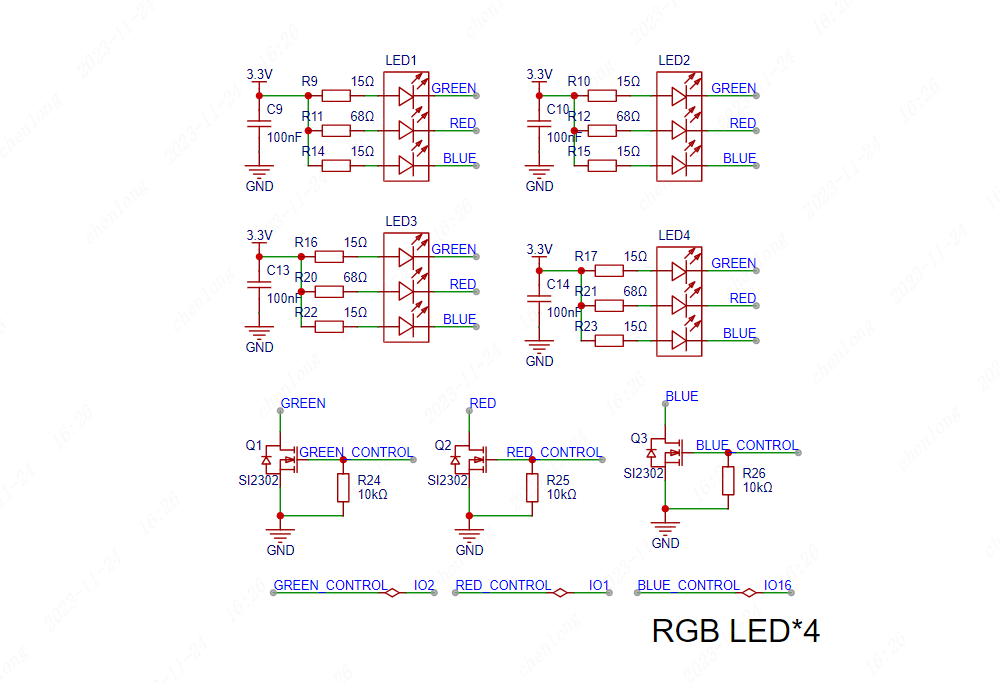
2.2 The LED lighting circuit
uses four RGB tri-color LEDs distributed around the perimeter of the board. Different display effects can be achieved by changing the brightness of different colors. Considering the different current requirements of red, blue, and green LEDs, different resistors are used in series in their respective branches. The brightness can be uniformly adjusted later by changing the resistance values. Each color LED is connected in series and controlled by a SI2302N channel MOSFET for unified conduction and shutdown. Brightness can also be adjusted by controlling the conduction time using PWM.
2.3 The main control section
uses the ESP32S3N8R8 module as the main control chip. Note that if speech recognition is required, the resource library is relatively large; it is recommended to choose Flash and PSRAM of 8MB or more. In modules with OSPI PSRAM (i.e., the built-in chip is ESP32-S3R8 or higher), pins IO35, IO36, and IO37 are for connecting to the integrated OSPI PSRAM and cannot be used for other functions. These pins need to be marked as "not connected."
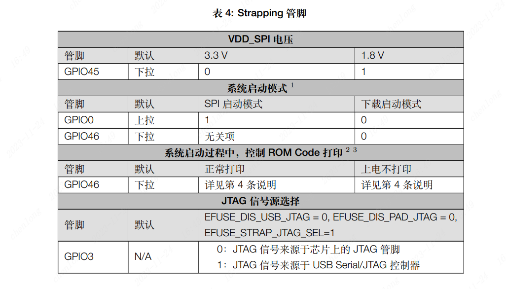
The ESP32S3 has four Strapping pins. When assigning pins, avoid adding pull-up or pull-down resistors to these pins to change their default state.

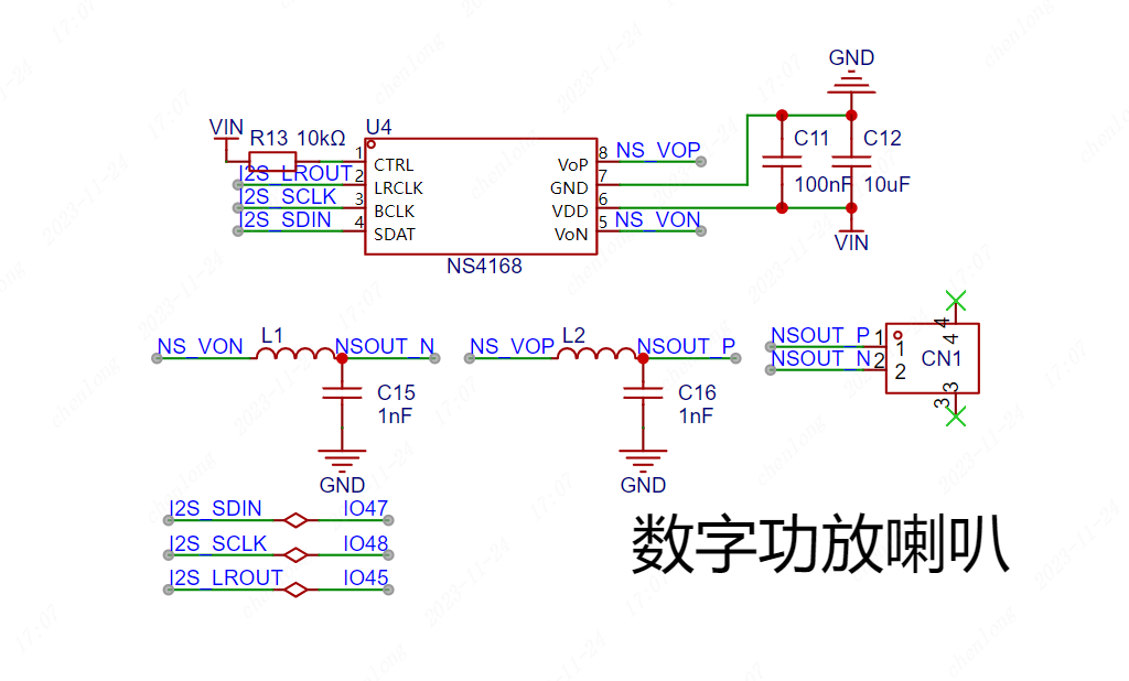
2.4 The speech recognition extension section
uses an I2S digital silicon microphone to receive the speech signal. At the I2S signal line, to obtain better anti-interference effect, a small series resistor can be used for impedance matching. A

Class D power amplifier chip with I2S signals is used for speech output. A ferrite bead and capacitor are added to the sound output path to form an LC filter circuit to reduce output interference. The external speaker is connected using a GH1.25*2P connector.
The ESP32S3 has two I2S controllers, and all I/O pins can be multiplexed into I2S pins via an internal matrix, allowing for flexible pin allocation.
A vibration sensor is included, enabling different lighting effects when a hand taps the table, increasing its versatility. The vibration sensor has an internal spring structure, which can be simply understood as a spring-loaded button.

III. Component Soldering
3.1
Bill of Materials Item No.
Name
Tag No.
Package
Parameters
Quantity
Component No.
1
TYPE-C Interface
USB1
USB-TYPE-C-SMD_TYPE-C-16P-QTWT
16PTTYPE-C
1
C5187472
2
Resistors
R1, R2
R0603
5.1K
2
C23186
3
Capacitors
C1, C3, C7
C0603
22uf
3
C59461
4
Capacitors
C2, C4, C5, C8, C9, C10, C11, C13, C14, C17, C18
C0603
100nf
11
C14663
5
LDO Step-Down Chip
U1
SOT-223-4_L6.5-W3.5-P2.30-LS7.0-BR
AMS1117-3.3
1
C347222
6.
Resistors
R4, R7, R13, R18, R19, R24, R25, R26
R0603
10K
8
C25804
7.
Vibration sensor
SW1
SW-TH_SW-18010P
SW-18010P
1
C2681585
8.
Resistors
R9, R10, R14, R15, R16, R17, R22, R23
R0603
15R
8
C22810
9.
Resistors
R11, R12, R20, R21
R0603
68R
4
C27592
10.
RGB lights
LED1, LED2, LED3, LED4
LED-SMD_6P-L5.0-W5.0-P1.60-LS5.4-TL
S6-5050RGBTA
4
C2827258
11.
N-channel MOSFETs
Q1, Q2, Q3
SOT-23-3_L2.9-W1.3-P1.90-LS2.4-BR
SI2302
3
C4748714
12
MCU
U3
WIRELM-SMD_ESP32-S3-WROOM-1
ESP32S3N8R8
1
C2913201
13
Buttons
SW2, SW3
SW-SMD_L3.9-W3.0-P4.45
TS-1088-AR02016
2
C720477
14
Resistors
R3, R5, R6
R0603
33R
3
C23140
15
Resistor
R8
R0603
100K
1
C25803
16
Capacitors
C6, C12
C0603
10uf
2
C96446
17
Class D Amplifier
U4
ESOP-8_L4.9-W3.9-P1.27-LS6.0-BL-EP2.0
NS4168
1
(No
18
ferrite beads
L1, L2
L0603
1kΩ@100MHz
2
C285931
19
Capacitors
C15, C16
C0603
1nf
2
C100040
20
Microphone
U2
LGA-8_L4.0-W3.0-P1.00-BL
1MSM261S4030H0R
1
C2840615
3.2 Soldering Auxiliary Tools
When soldering, you can click on the tools in the top menu bar of JLCPCB EDA's PCB page and select soldering auxiliary tools. This will take you to an interactive BOM page, which displays the coordinate positions of the components on the PCB board in real time. You can check to hide or show the soldered components for high-efficiency soldering.

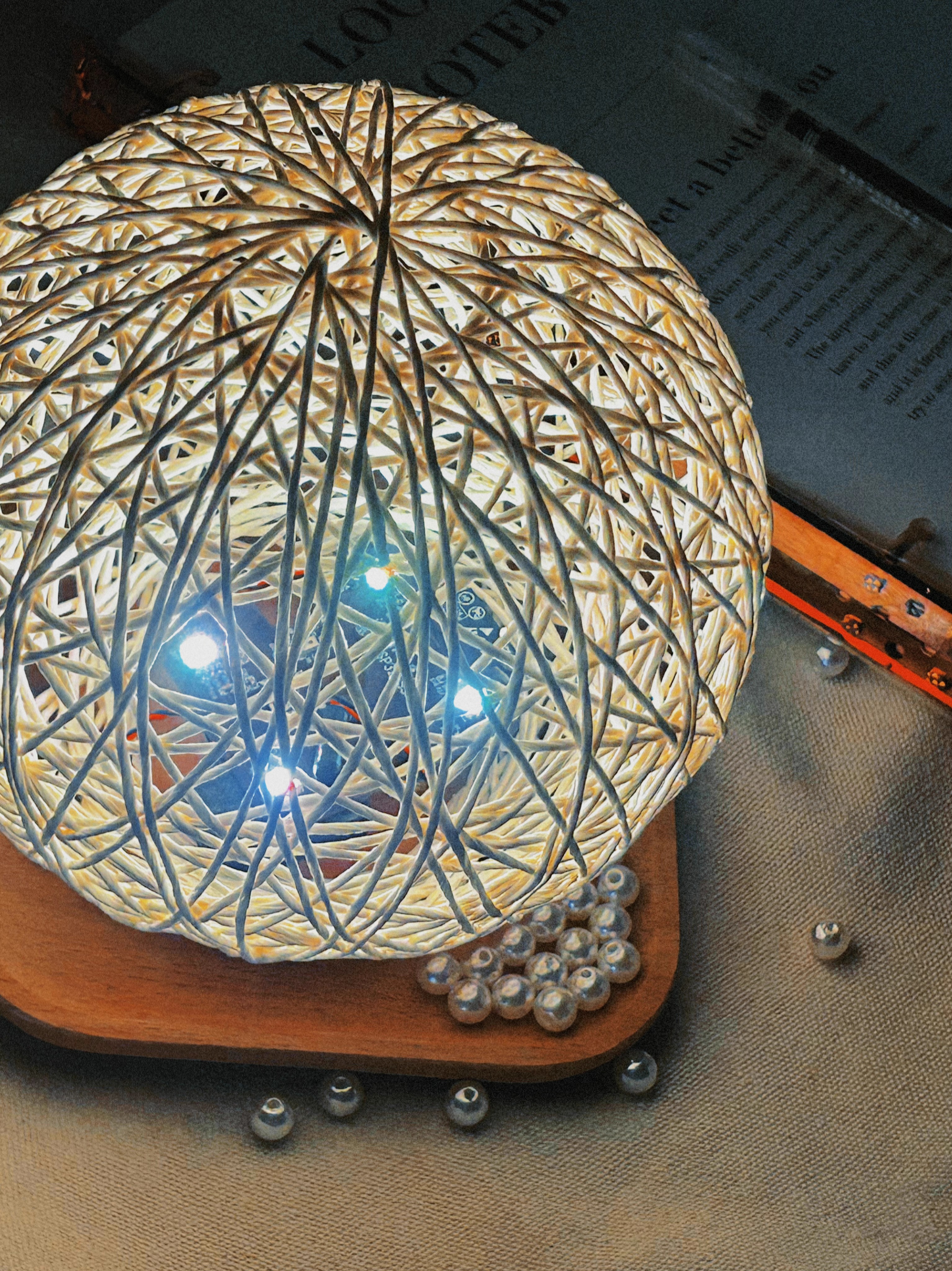
IV. Physical Demonstration
4.1 3D Rendering


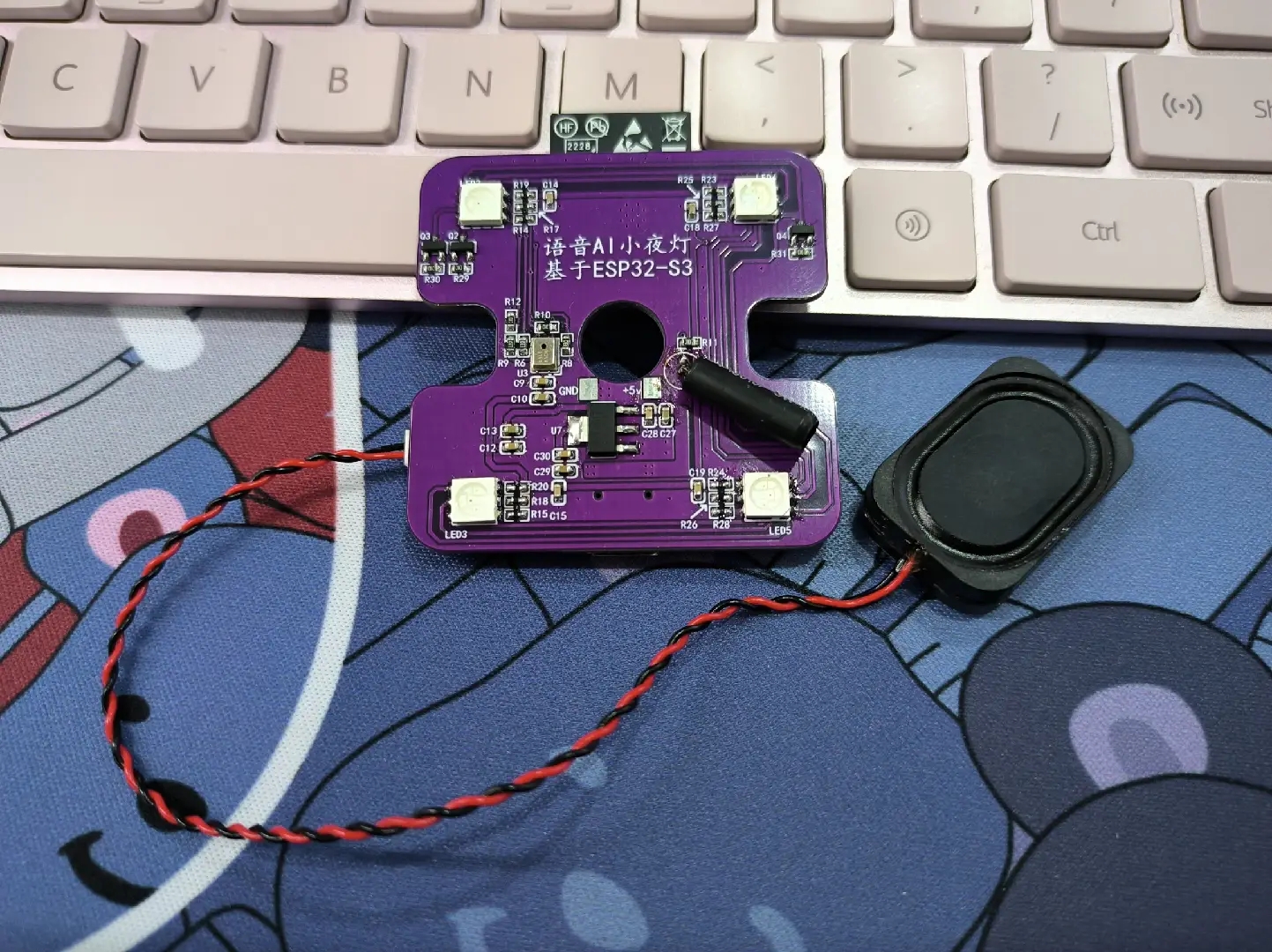
4.2 Finished Product

4.3 Software Resource Link: Espressif Voice-Assisted Vine Ball Lamp
4.4 Video Tutorials
: Lesson 1 Project
Introduction Lesson 2 Schematic Drawing ( Part 1) Lesson 3 Schematic Drawing ( Part 2 ) Lesson 4 PCB Design ( Part 1) Layout Techniques Lesson 5 PCB Design ( Part 2) Routing Techniques 4.5 Effect Demonstration


 京公网安备 11010802033920号

 171-004-26P-.150


