Last Update: 2024-10-09 Fixed E73 version files.
Introduction:
With the increasing popularity of passwordless login via Passkey, and the fact that the open-source password manager Bitwarden itself supports passwordless login, having a secure key has become necessary. However, commercially available products are too expensive, hence the creation of a secure, inexpensive, and compact device.
This project is based on Google's open-source project OpenSK, modified and adapted. Google is a member of the FIDO Consortium, and the code is FIDO certified, ensuring security. The bootloader is based on Adafruit_nRF52_Bootloader, modified and adapted to support uf2 file burning, facilitating future firmware updates.
The hardware
is divided into two versions: one using the nRF52840 chip (hereinafter referred to as the MINI version), and the other using the E73 module (hereinafter referred to as the E73 version).
The MCU uses the nRF52840 with an independent security system; a used one costs around 5 yuan.
It uses an external high-speed crystal oscillator (required for USB functionality) and an internal low-speed crystal oscillator.
A TVS circuit is retained to prevent accidental damage to the device or computer due to electrostatic discharge.
An NFC pad is provided (OpenSK will support NFC functionality in the future).
Touch-sensitive buttons are used, which are more convenient than microswitches; a microswitch on the back is used to enter the programming mode.
The MINI version
features a USB Type-C interface and a very small size.
It uses a built-in LDO power supply to reduce external components.
Bluetooth-related circuitry has been removed, as OpenSK will not support Bluetooth functionality in the future.
The LED and touch-sensitive buttons are located at the rear, and the casing is 3D printed.
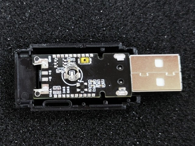
The E73 version
features a USB Type-A interface, which can be fitted with a Type-C port for dual interfaces. It
uses a built-in DC-DC power supply and
adopts the standard USB flash drive form factor B, allowing it to fit into a standard reference USB flash drive casing.
Image Preview
MINI Version:
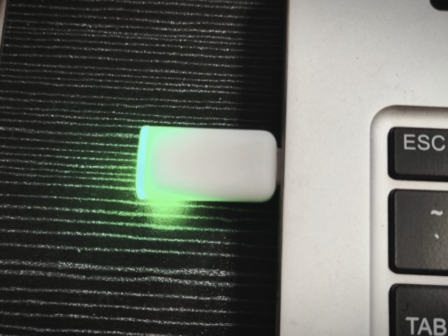
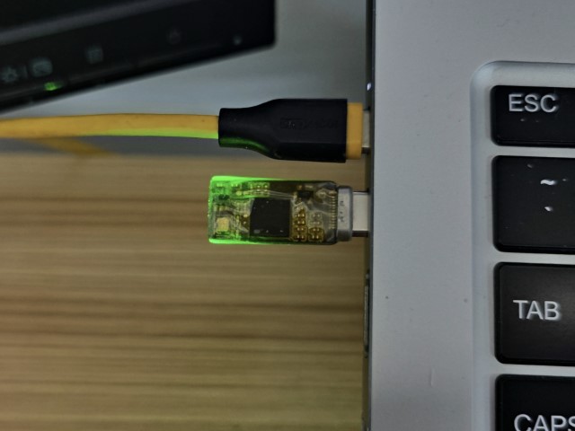
E73 Version:
Replica Notes
The BOM at the bottom of the project lists two versions, so please export a single
MINI version from the project:
When flashing the firmware, select the one with "MINI" in the name, do not select the wrong version!!
The prototype thickness is 0.8 mm, otherwise the Type-C interface cannot be soldered on;
the nRF52840 is in an AQFN-73 package, which is somewhat difficult to solder, requiring at least a heating table or hot air gun;
when soldering, solder the side with the chip first, then flash the Bootloader using OpenOCD, and measure and verify that there are no problems before soldering other components;
the notch at the rear can be cut off after soldering, the metallized side is the touch area, or it can be kept as a lanyard hole;
the back cover of the 3D shell is printed in white or transparent, it is uncertain whether black will allow light to pass through.
E73 Version:
When flashing the firmware, select the one with "E73" in the name, do not select the wrong version!!
The prototype thickness is 1.6mm.
If the reference casing is not used, a Type-C male connector module with a small board can be soldered to the tail. Pay attention to the pin definition order.
Choose a touch spring with a bottom diameter of approximately 4mm. Stainless steel springs may not solder well; you can use copper foil tape to attach them.
Update Log:
2024-10-09 Fixed E73 version file
; 2024-04-10 Added E73 module version for easier soldering
; 2024-03-23 Added 3D printed casing file;
2024-03-17 Added Windows environment flashing instructions;
2024-02-05 First
firmware release flashing;
First bootloader flashing.
This tutorial uses Picoprobe (DAPLink) in a Linux (WSL2) environment for flashing. Only an RP2040 development board is needed.
On Windows, you can use WSL2 + usbipd-win, or directly install the Windows version of OpenOCD (https://gnutoolchains.com/arm-eabi/openocd/).
For other flashing methods, please refer to this document: https://github.com/joric/nrfmicro/wiki/Bootloader.
To start OpenOCD, run
`openocd -d2 -f interface/cmsis-dap.cfg -f target/nrf52.cfg -s tcl`. Keep the previous window open and run the following command in a new window: `telnet localhost 4444`. To unlock the chip and program it , run the following commands in the previous telnet window, noting that in lines 4-5, the hex filename and path should be replaced with the actual file (relative to the OpenOCD command path; use an absolute path if unsure): `nrf52_recover nrf5 mass_erase flash write_image xxx_bootloader-xxxx.hex flash verify_image xxx_bootloader-xxxx.hex reset run`. To enter DFU mode , press and hold the DFU button (the large button on the back) and insert the device into the computer. The LED on the device will blink, and a storage device will appear on the computer, indicating successful DFU mode entry. Then, copy the corresponding .uf2 file into the storage device to complete the programming. Upgrade the Bootloader [Not required for the first flash]. For subsequent Bootloader version upgrades, enter DFU mode and copy the updated file (update-xxx_bootloader-xxxx_nosd.uf2) from the attachment into the DFU mode. To flash OpenSK , enter DFU mode and copy the OpenSK firmware (xxx_opensk_xxx.uf2) from the attachment into the DFU mode. Alternatively , compile the firmware yourself (optional) and compile the Bootloader.
The bootloader is based on Adafruit_nRF52_Bootloader. Normally, the firmware in the attachment is sufficient. If you need customization, you can compile the firmware yourself.
For dependency installation,
refer to: https://github.com/adafruit/Adafruit_nRF52_Bootloader?tab=readme-ov-file#prerequisites.
Download the source code:
`git clone -b master https://github.com/adafruit/
Adafruit_nRF52_Bootloader`. Navigate to Adafruit_nRF52_Bootloader. Run the command:
`git submodule update --init`. Apply the patch : Copy the patch file `OpenSK_Bootloader_xxxx.patch` from the attachment to the project root directory, and then run the command: `git apply OpenSK_Bootloader_xxxx.patch`. Compile: `make BOARD=pca10059 clean && make -j BOARD=pca10059 all` . The generated files will be stored in the `_build/build-pca10059` directory. Compiling OpenSK: OpenSK is based on modified OpenSK. Normally, the firmware in the attachment can be used. If you need to customize it, you can compile the firmware yourself. For dependency installation and compilation, refer to: https://github.com/google/OpenSK/blob/2.1/docs/install.md#software-requirements. Download source code: `git clone -b 2.1 https://github.com/ google/ OpenSK.git` `cd OpenSK` `./ setup.sh` `wget -P tools https ://github.com/microsoft/ uf2/raw/master/utils/uf2conv.py` ` wget -P tools https://github.com/microsoft/uf2/raw/master/utils/uf2families.json` `chmod a+x tools/uf2conv.py` Apply patch: Copy the patch file `OpenSK_xxxx.patch` from the attachment to the project root directory, and then run the command: `git apply OpenSK_xxxx.patch` `cp -r boards/nordic/. third_party/tock/boards/nordic` Compile: `./deploy.py --board=nrf52840_dongle_dfu --programmer=none --opensk` The compiled files generated by `./tools/uf2conv.py -c -f 0xada52840 -o target/nrf52840_dongle_dfu_merged.uf2 target/nrf52840_dongle_dfu_merged.hex` will be stored in the `target` directory. It depends on `google/OpenSK Adafruit_nRF52_Bootloader`.


 京公网安备 11010802033920号

 NRSG681M25V8X11.5TRF


