Please refer to the attached BOM list!
The system-generated
BOM list may contain errors!
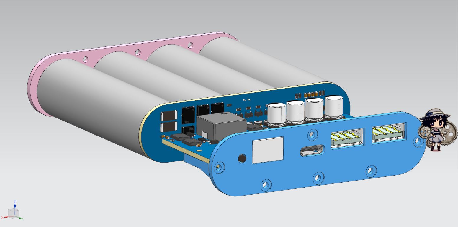
This 100W bidirectional fast charging power bank motherboard and protection board, based on the Ingenic IP5389-BZ main controller and BYD BM3451TNDC_T28A protection chip
, is modified from Xiaoyu's version. Thanks to the developer for the open-source code
: https://oshwhub.com/wzw666/IP5389PRO
https://oshwhub.com/wzw666/bm3451
==============MASTER WARNING==============
This project may contain the following:
high current board burn-in, pin bridging, VCC short circuit, reverse charging, copper foil detachment, I2C interface with UART.
If you experience any discomfort, please adapt as soon as possible
. ============== Answers are prohibited within the binding line. ===============
Materials used:
IP5389 link (click to jump)
, BM3451 link (click to jump)
188 Digital Tube Connection (Click to Jump)
M2*3.5*4 Copper Insert Nut Connection (Click to Jump)
M2*5 Flat Head Screw Connection (Click to Jump)
M2*8 Screw and Nut Set (For Locking the Motherboard)
Main Control Board:
Except for the 0.4mm pin spacing of the main control board, the rest are soldered using standard methods.
Solder the main control board first, then the resistors and capacitors, followed by the sampling resistor, and finally the digital tube, tactile switch, and four electrolytic capacitors. Do not connect the Type-C connector to the Type-A port yet.
Insert the battery; the digital tube will display 0%, but ignore this for now. Use a multimeter in voltage mode. With the black probe grounded and the red probe used to measure TP8, there should be a voltage of 11.2~16.8V. If it exceeds this range, check the protection board or the battery.
Next, insert the charger's C port into the motherboard's C port. At this time, the digital tube will display the current battery level. Measure TP2 to see if there is a voltage of 4.8V or higher. If not, check the motherboard's C port soldering.
After completing the previous step, measure whether the voltage of TP8 is consistent with that of TP2. If they are inconsistent, check whether there are any problems with the H-bridge soldering and the main controller soldering.
After all the above steps are correct, connect the A port, connect the wires, and measure the voltages of TP3 and TP4 accordingly. Alternatively, you can output from the C port and measure the TP2 voltage (when dual ports or more are outputting simultaneously, the TP1 voltage will only be 5V. When using a single port, it can trigger four voltages: 5V, 8V, 12V, and 20V, but the 20V voltage is only available from a single C port output; a single A port can only reach a maximum of 12V).
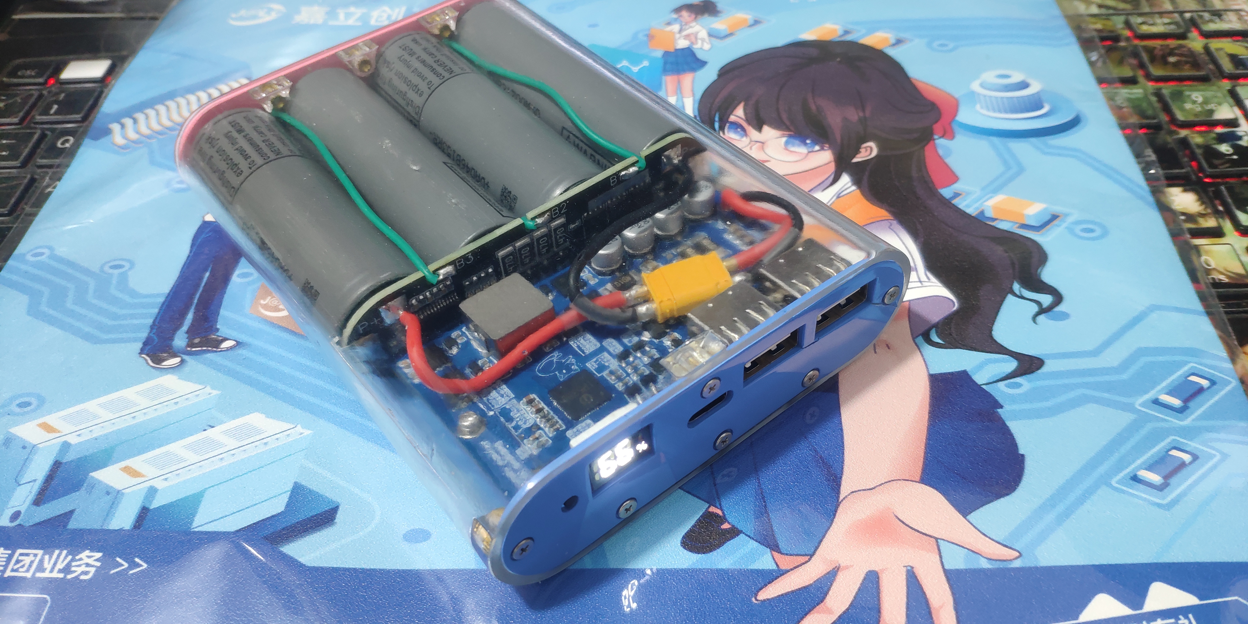
The motherboard soldering is now complete.
Lithium battery protection board:
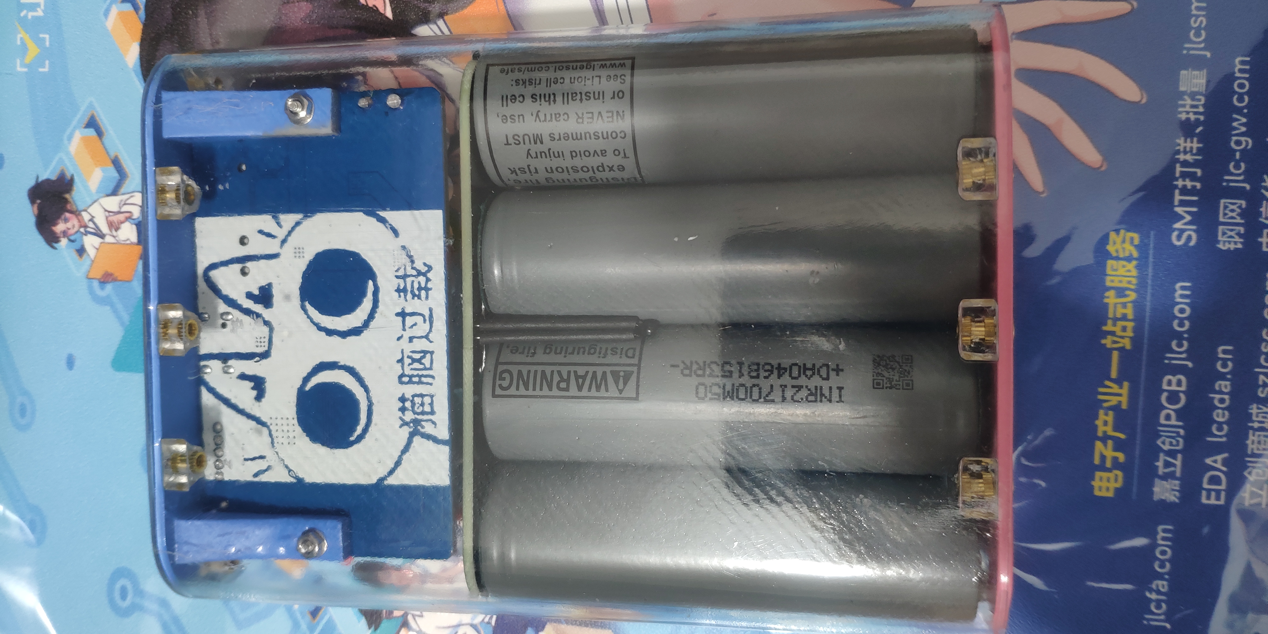
Protection board specifications: 4 series, protection current 20A, long-term use within 15A.
First solder BM3451, then resistors and capacitors, dissipation resistors, equalization MOSFETs and sampling resistors, and finally 4C302.
Note:
Put as much solder as possible on the MOSFET window area to ensure that the board will not burn under high current.
LEDs can be back-blown using medium-temperature solder paste to prevent the LED lens from turning yellow from heat.
The soldering order of the protection board is B-, B1, B2, B3, B+, otherwise there is a probability of various strange problems (such as the output voltage only 8V).
As for the battery, I personally use LG M50LT, and I have not tested other battery cells.
==============Answering is prohibited within the binding line===============
Then just draw a simple diagram, super easy, right?
Drill the holes, do the countersunk design, and then *duang*

—whoosh, the insert nut is done! Isn't that simple?
Then *duang*—after a few days at LCSC 3D Printing, it's assembled when I get home. I also got a mouse pad by the way.
When ordering from LCSC 3D, choose 8001 resin for the shell. The post-processing costs almost match the shell material itself.
Do not force the copper insert nut by squeezing or baking it at high temperatures, as it may break.
The correct method is to first grind the mounting hole with a 3mm drill bit before installing the part. You can make it a little bigger, up to 3.3mm. Then put the nut on a pointed soldering iron and heat it for 5-8 seconds. Remove it with tweezers and slowly press it into the mounting hole. After installation, use a 502 glue applicator with a glue dropper to drip a little bit into the nut gap. Just enough to seep the glue in, don't use too much.
=================END====================


 京公网安备 11010802033920号

 PE6015


