The idea
originated from the fact that children are always reluctant to have their temperature taken when they are sick. Traditional mercury thermometers are slow, and the child keeps asking, "Are you alright yet? Are you alright yet? Are you alright yet?" Getting impatient, they finally take out the thermometer, ruining the reading, and I'm even more frustrated! Ear thermometers and forehead thermometers on the market, after buying them, turned out to have too much accuracy, even worse than mercury thermometers. So I wanted a cheap, easy-to-use, accurate, and fast thermometer. Having not found one, I decided to make one myself, so that parents could know their children's temperature faster and more accurately.
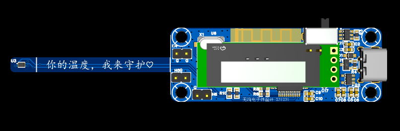
Your temperature, I'll protect—that's my initial intention.
Project Objectives
: To solve the problem of children being unwilling to cooperate with temperature checks when sick, and the inability to monitor fever in real time when taking axillary temperature.
Product Features:
1- High accuracy, less than 0.1 degrees Celsius;
2- Equipped with a display screen, easy for elderly people who don't know how to use mobile phones;
3- Most importantly, supports Bluetooth transmission, supporting BLE and SPP, connecting to both mobile phones and computers;
4- Long runtime, can be used continuously for more than 12 hours.
5. Easy to use; no need to constantly check the temperature. Data is received directly from a mobile phone or computer. Alarm functions can be customized, making it convenient when supervising children, as you might not know when the temperature will rise again and you can't even take a nap.
After multiple iterations, the following is a summary:
Making a product is really tiring, full of pitfalls, and I couldn't even climb out of the all-nighters.


The product design and verification
are introduced in four parts. Countless problems were encountered along the way; making a good product is truly not easy.
Hardware Design
System Block Diagram:

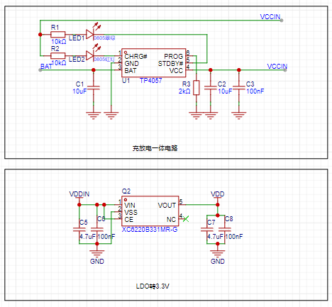
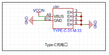
The power supply section
charges the product via Type-C, using the TP4057 charging and discharging chip. This chip is inexpensive and supports boost voltage to ensure stable system power supply.
The system uses a 3.3V power supply, therefore an LDO is used for voltage conversion.
The lithium battery has a 200mA capacity, with the following specifications

. The connection method is soldering, with a reserved 2.54mm header for easy adjustment.

To save costs, a 6-pin Type-C connector was chosen; actually, microUSB is cheaper and was replaced in the second version.
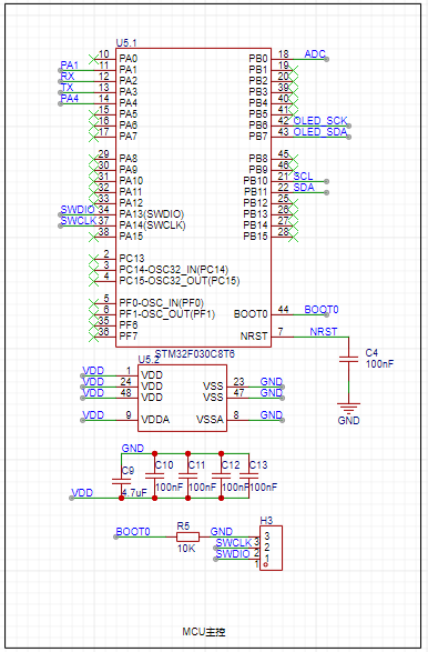
The main control unit
of the system uses the STM32F030C8T6. Below is an introduction to this chip; I chose it because it's suitable: 1- Low power consumption, M0 core; 2- Inexpensive, reducing costs; 3- Abundant peripherals, sufficient for most uses. I welcome recommendations for more suitable main control units.
The STM32F030x4/x6/x8/xC series microcontrollers integrate a high-performance Arm® Cortex®-M0 32-bit RISC core operating at 48 MHz, high-speed embedded memory (up to 256 KB of Flash and up to 32 KB of SRAM), and a wide range of enhanced peripherals and I/O. All devices provide standard communication interfaces (up to 2 I2C, up to 2 SPI, and 6 USART), one 12-bit ADC, seven general-purpose 16-bit timers, and one advanced control PWM timer. The STM32F030x4/x6/x8/xC series microcontrollers operate over a temperature range of -40 to +85°C and from 2.4V to 3.6V. A complete set of power-saving modes allows for the design of low-power applications. The STM32F030x4/x6/x8/xC series microcontrollers include devices in four different packages, ranging from 20 to 64 pins. Depending on the selected device, different sets of peripherals are included. These features make the STM32F030x4/x6/x8/xC series microcontrollers suitable for a wide range of applications, such as application control and user interfaces, handheld devices, A/V receivers and digital TVs, PC peripherals, gaming and GPS platforms, industrial applications, PLCs, inverters, printers, scanners, alarm systems, video intercoms, and AC.
The main controller performs the following functions:
1- ADC acquisition, which detects the lithium battery level;
2- Serial communication, controlling the Bluetooth chip and sending data;
3- IIC communication, controlling the temperature sensor, configuring and initializing it, and most importantly, reading the temperature;
4- IIC communication, displaying battery level, Bluetooth connection status, real-time temperature, measurement duration, etc.;
5- Other expandable functions .
The Bluetooth part
uses the KT6368A chip, which supports dual-mode. Specific specifications are as follows. To reduce power consumption, it is recommended to use the KT6328A, but it only supports BLE.
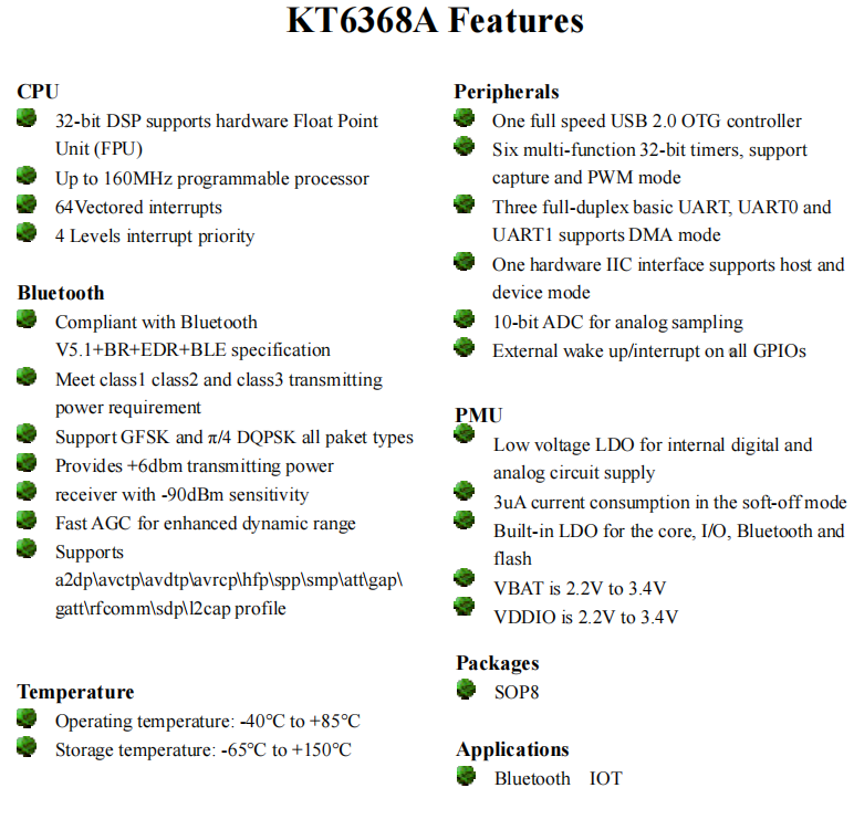
The relevant schematic diagram is shown below.

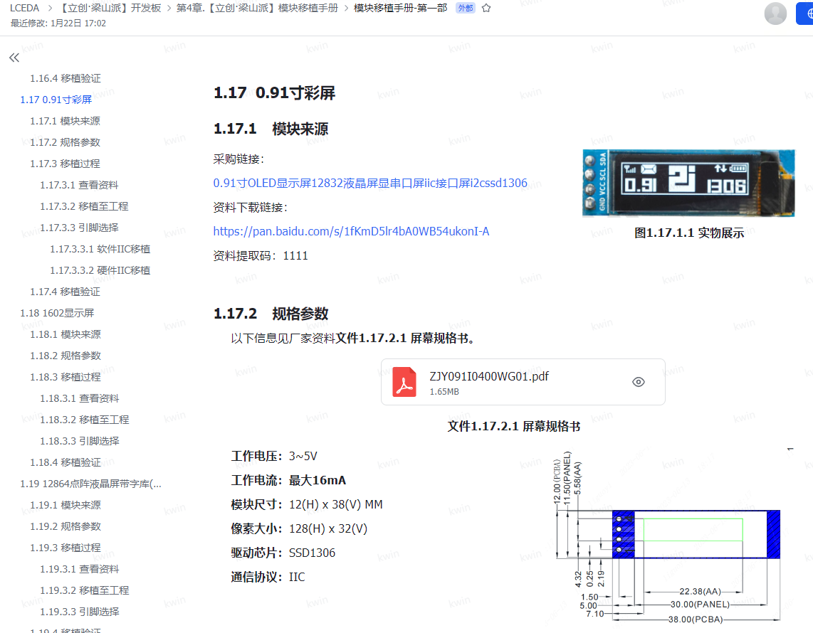
For the display
, I used a 0.91-inch OLED module with only 4 pins, as shown below.

I purchased it cheaply from LCSC; it's white light. I also tried blue light, which worked well. It depends on personal preference. I bought it on Taobao. For

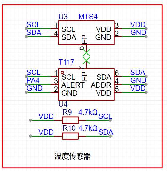
the temperature sensor
, I selected two types to verify the effect. You can refer to the LCSC manual for details.
These are the two most accurate and affordable soldering irons I could find, offering the best value for money. Feel free to purchase them from LCSC's online store.
Soldering is quite complicated, so choose a good quality soldering iron, such as LCSC's Huanghua brand. LCSC, remember to pay me for advertising!
The T117
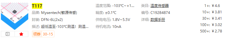
features ultra-low temperature measurement down to -103℃! Temperature accuracy ±0.1℃@+28~+43℃, I2C/single-bus digital output, 16-bit resolution/0.004℃, configurable temperature measurement as fast as 2.2ms, supports 4 I2C communication addresses; ultra-low power consumption 2μA@1HZ, 1.8V~5.5V wide voltage supply, small 2*2*0.75mm size, DFN6L package, built-in 112bit EEPROM user space. Widely used in smart wearables, thermometers, animal temperature detection, medical electronics, heat meters, gas meters, water meters, and other industries.
The MTS4

features I2C protocol digital output, compatible with both digital single-bus and digital sensors. Temperature measurement accuracy is ±0.1℃@+28℃~+43℃, with 16-bit output at 0.004℃. Measurement speed is configurable at 15.3ms/8.5ms/5.2ms/2.2ms. It boasts ultra-low power consumption of 3.1μA (AVG=16, 1 measurement/s), an ultra-small 1.6x1.2x0.55mm size, DFN4L package, and built-in 112-bit EEPROM user space. It is widely used in surface-mount small-sized smart wearables, electronic thermometers, animal temperature detection, medical electronics, cold chain logistics, and heat, gas, and water meters.
The corresponding
PCB design
uses a 4-layer board with a thickness of 1.6mm. This is primarily due to the sensor's width; it's only a few millimeters wide, which is somewhat flimsy. We'll consider making it wider and thicker later, but that would be significantly more expensive. For the sake of simplicity, the length is kept under 10cm.
The mounting holes here are M3, which I feel is too large; M2 would be sufficient. I'm a novice when it comes to 3D
shell design
, so my design is relatively simple. I'm learning by making mistakes step by step. I made two versions in total, and the second version hasn't come back yet.
The design software used is LCSC's EDA, which is indeed very user-friendly. More tutorials are gradually appearing now. I'm very grateful for their technical support; it's excellent, and the feedback is very timely. Mr. Ye (LCSC's CEO) is very diligent; LCSC, please remember to give him a bonus, at least a chicken leg! I feel LCSC will continue to grow and improve; remember to buy their stock, it's likely to surge.

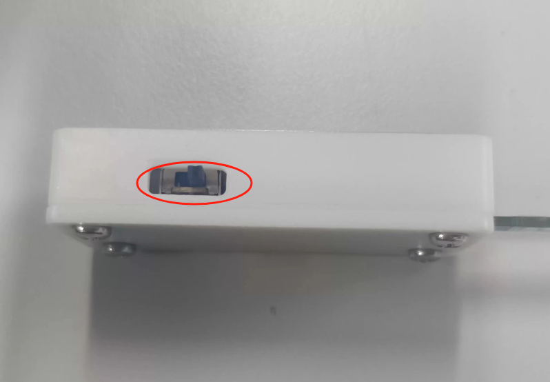
The casing design is very simple, but you need to calculate all the dimensions yourself, as LCSC's 3D model might be inaccurate.

For example, my switch, which I designed to be centered, actually has an error: as shown in the picture below, it's toggled too high.
Regardless, I'm very satisfied with the finished product. Everyone should use it more and explore it further. There are coupons now, giving us a chance to experiment.
I made a few as shown below; with the casing, the product's quality is greatly enhanced.
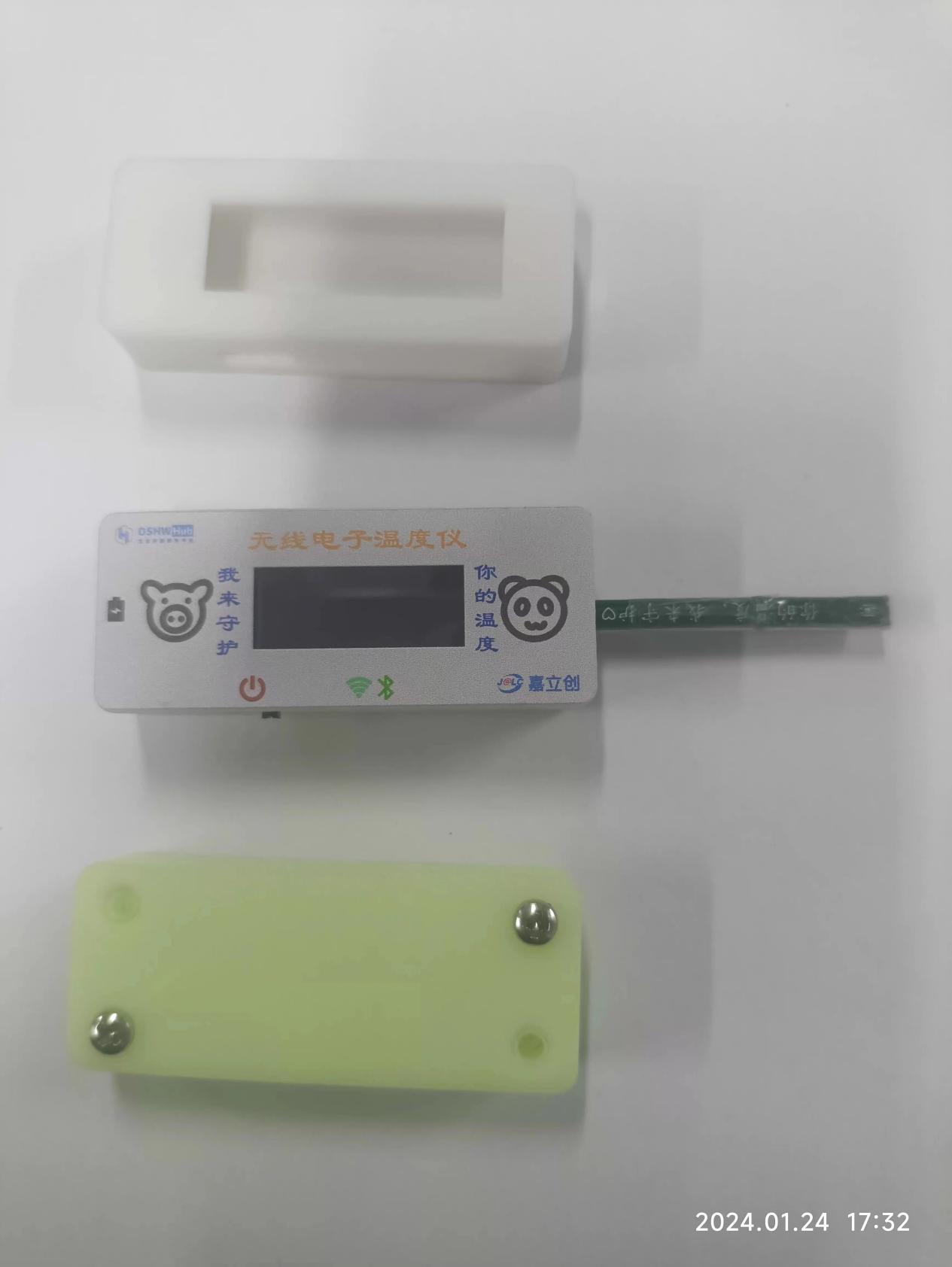
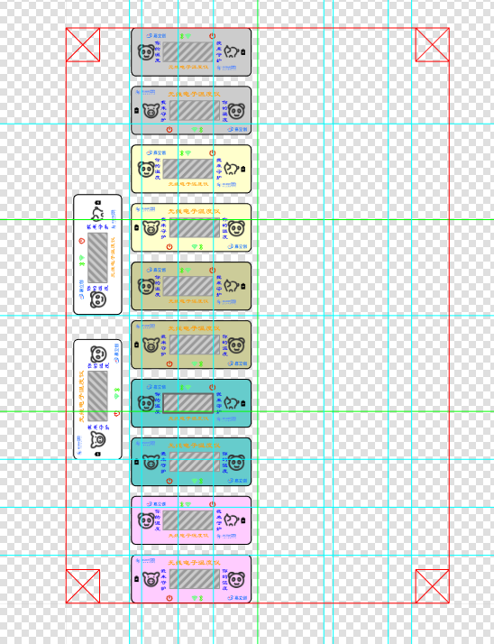
The panel design
also used LCSC's EDA to save money. This isn't as user-friendly as 3D design; many positions require calculation. Here's a tip: export the PCB's DXF file first, which makes positioning much easier.
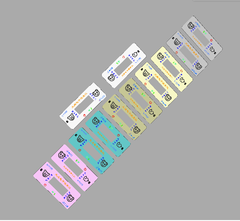
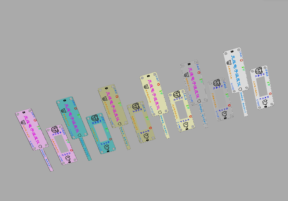
I went through quite a few detours, making it twice, once with acrylic and once with a PET mold. It's really beautiful! I made many colors, and you can easily change the shell and panel.
The design is as follows:

The actual product is shown below .
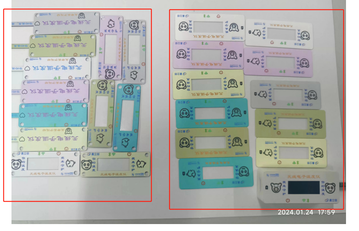
The two versions are as follows:
1- Different materials: the first version is acrylic, the second version is PET.
2- The second version has adhesive backing .
3- The first version has mounting holes, allowing for independent assembly without a shell.
4- Different sizes: the second version is 1mm larger.
Both versions have their advantages, and I tried them both. They both feel good.
The program design and
development tools and environment
use a combination of CubeMX and Keil5, developed in C language.
Design concept:
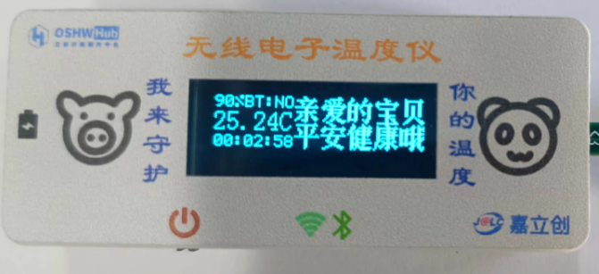
1- Power sampling: Data is collected through timer + DMA + DAC. The timer is set for 2 seconds. Why 2 seconds? To reduce power consumption. The previous 1 second refresh felt a bit too fast.
2- Bluetooth connection detection: Read the PA1 pin status. If connected, the display shows OK; otherwise, it shows NO.
3- Temperature is read every two seconds, and the status register is used to determine if the temperature conversion is complete.
4- OLED display updates every 2 seconds.
The effect is shown in the following image: For details on
the Bluetooth
driver implementation for the KT6368A, please refer to the Liangshanpai module porting manual. I will not elaborate on the specific implementation here. The following link provides
the module porting manual - Part 1:
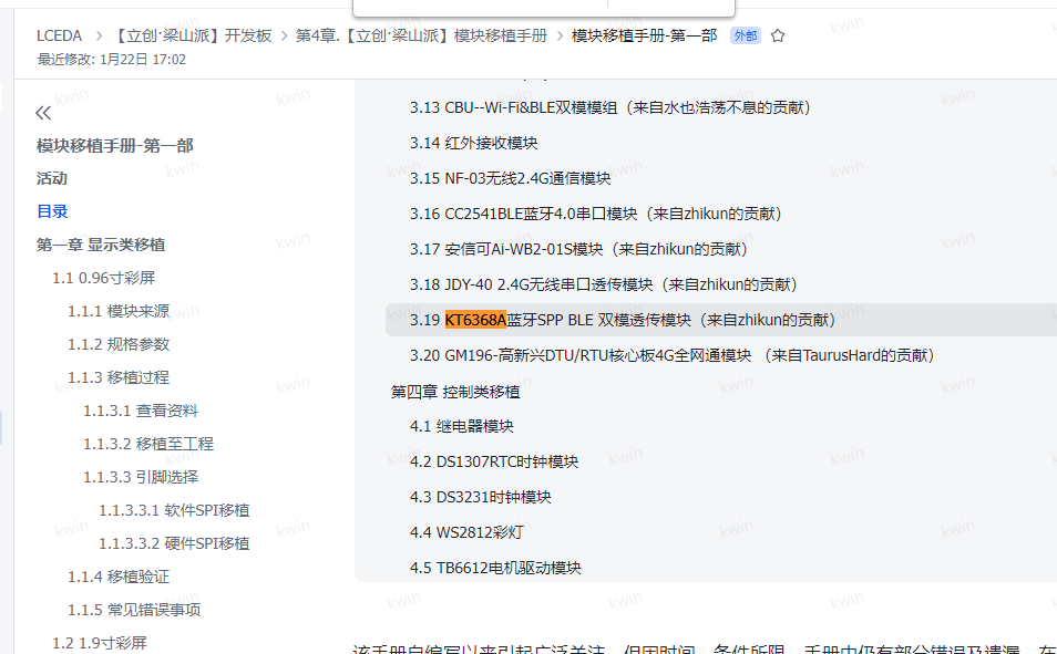
OLED Driver
. Many pre-ported versions of this 0.91-inch display are available online, so I will not repeat them here. You can refer to the Liangshanpai module porting manual for details, as shown in the following link:
Module Porting Manual - Part 1:
Temperature Sensor Driver .
Due to the limitations of manual soldering, I have only successfully soldered the T117 chip so far. Here, I will demonstrate the writing of this driver, as shown below.
Here is the header file .
C++ #ifndef __SENSER_H #define __SENSER_H #include "stm32f0xx_hal.h" typedef enum { //Temp_Cmd //Temp measurement mode CONTI_CONVERT = 0x00, //Continuous temperature measurement STOP_CONVERT = 0x40, //Stop temperature measurement SINGLE_CONVERT = 0xc0, //Single temperature measurement //Heating mode OFF_HEATING = 0xf0, //Clear low bits to 0, heating off ON_HEATING = 0x0A, //Heating on //Temp_Cfg //Temp measurement frequency FRE_8times = 0x00, //8 times per second FRE_4times = 0x20, //4 times per second FRE_2times = 0x40, //2 times per second FRE_1times = 0x60, //1 time per second FRE_2s = 0x80, // FRE every 2 seconds 1 time _4s = 0xa0, // FRE every 4 seconds 1 time _8s = 0xc0, // FRE every 8 seconds 1 time _16s = 0xe0, // FRE every 16 seconds 1 time // Average number of times AVG_1 = 0xe7, // Clear bit to 0, conversion time 2.1ms AVG_8 = 0x08, // Conversion time 5.2ms AVG_16 = 0x10, // Conversion time 8.5ms AVG_32 = 0x18, // Conversion time 15.3ms // Low power mode OFF_PD = 0xfe, // Clear bit to 0, do not enter low power mode ON_PD = 0x01, // Enter low power mode // EE_Cmd EE_DOWN = 0xb6, // Load EE value into register EE_COPY = 0x08, // Save the value in register into EE EE_RESET = 0x6a, //Soft reset, loads the EE value into the register. For the part corresponding to EE, the register value is restored to the stored value of EE; for the part not corresponding to EE, the register value is restored to the default value. //Alert_Mode //Alarm switch OFF_ALERT = 0x00, //Clear to 0, alarm off ON_ALERT = 0x80, //Alarm on //ModeTL_CLEAR = 0xbf, //Bit clear to 0, TL is the alarm clear threshold TL_ALERT = 0x40, //TL is the lower threshold of the alarm threshold //Polarity ALERT_LO = 0xdf, //Bit clear to 0, active low ALERT_HI = 0x20, //Active high //Alarm port mode selection ALERT_IO = 0xef, //Bit clear to 0, used for temperature alarm CONVERT_FINI = 0x10, //Used as temperature measurement completion flag} I2C_CMD;typedef enum {Temp_lsb = 0x00, //Temp_msb = 0x01, //Crc_temp = 0x02, //Status = 0x03, //Temp_Cmd = 0x04, //Default value 0x40: Stop measurement, no heating Temp_Cfg = 0x05, //Default value 0x69: Once per second, AVG_8, enter low power Alert_Mode = 0x06, //Default value 0x00: Alarm off, alarm mode is TL to clear alarm, alarm low level is active, flag bit indicates temperature alarm Th_lsb = 0x07, Th_msb = 0x08, Tl_lsb = 0x09, Tl_msb = 0x0A, Crc_scratch = 0x0B, EE_Cmd = 0x17, //Default value 0x00: No operation Romcode1 = 0x18, Romcode2 = 0x19, Romcode3 = 0x1A, Romcode4 = 0x1B, Romcode5 = 0x1C,Romcode6 = 0x1D,Romcode7 = 0x1E,crc_romcode = 0x1F,} REG;void T117_Init(void);uint8_t T117_ID(void);//Get ID uint8_t T117_R_REG(uint8_t REG,uint8_t *DAT);//Read register uint8_t T117_W_REG(uint8_t REG,uint8_t DAT);//Write register uint8_t T117_R_TEMP(float *DAT); //Read temperature #endif
This is a C file
C++ #include "SENSOR.h" #include "myiic.h" #define T117_WADD 0x80 #define T117_RADD 0x81 // Temperature measurement instruction register (Temp_Cmd), address 0x04 // #define Temp_Cmd 0x04 // Configuration register (Temp_Cfg), address 0x05 // #define Temp_Cfg 0x05 // Status register (Status), address 0x03 // #define Status 0x03 /* Bit content description Default value 7 High temperature alarm tracking 0: Temperature alarm not triggered 1: Temperature alarm triggered '0' 6 Low temperature alarm tracking 0: Temperature alarm not triggered 1: Temperature alarm triggered '0' 5 Temperature conversion status 0: Temperature conversion completed 1: Temperature conversion in progress '0' 4 E2PROM status 0: Not in read/write state 1: In read/write state '0' 3 Heating Status 0: Not in heating status 1: In heating status '0' 2 Temperature Alarm Error Message 0: TH greater than TL 1: TH less than or equal to TL '0' 1: 0 Reserved '00' */// Alarm Mode Register (Alert_Mode), address 0x06 //#define Alert_Mode 0x06/* Bit Content Description Default Value 7 Alarm Function Switch (Alert_en) 0: Off 1: On '0' 6 Alarm Mode (IM) Selection 0: Alarm above TH + Alarm clear below TL 1: Alarm above TH + Alarm below TL '0' 5 Alarm Polarity (POL) Selection 0: Active low 1: Active high '0' 4 Alarm Port Output Mode (FUNC) Selection 0: Output temperature alarm flag 1: Output temperature measurement completion flag '0' 3: 0 Reserved '0000' */ void T117_Init(void){ T117_W_REG(Temp_Cmd,0x00);//Continuous temperature measurement without heating T117_W_REG(Temp_Cfg,0x99);//0.5 times per second, averaged over 32 times, enter low power T117_W_REG(Alert_Mode,0x10);//No alarm, output temperature measurement completion flag} uint8_t T117_ID(void) //Get ID{uint8_t temp=0;IIC2_Start();IIC2_Send_Byte(T117_WADD);temp=IIC2_Wait_Ack();if(temp) {IIC2_Stop();return 1;}IIC2_Send_Byte(0x19);temp=IIC2_Wait_Ack();if(temp) {IIC2_Stop();return 1;} 2;}IIC2_ReStart();IIC2_Send_Byte(T117_RADD);temp=IIC2_Wait_Ack();if(temp) {IIC2_Stop();return 3;}temp=IIC2_Read_Byte();IIC2_NAck();IIC2_Stop();return temp;}uint8_t T117_R_REG(uint8_t REG,uint8_t *DAT) //Read register {uint8_t temp=0;IIC2_Start();IIC2_Send_Byte(T117_WADD);temp=IIC2_Wait_Ack();if(temp) {IIC2_Stop();return 1;}IIC2_Send_Byte(REG);temp=IIC2_Wait_Ack();if(temp) {IIC2_Stop();return 2;}IIC2_ReStart();IIC2_Send_Byte(T117_RADD);temp=IIC2_Wait_Ack();if(temp) {IIC2_Stop();return 3;}*DAT=IIC2_Read_Byte();IIC2_NAck();IIC2_Stop();return 0;}uint8_t T117_W_REG(uint8_t REG,uint8_t DAT) //Write register {uint8_t temp=0;IIC2_Start();IIC2_Send_Byte(T117_WADD);temp=IIC2_Wait_Ack();if(temp) {IIC2_Stop();return 1;}IIC2_Send_Byte(REG);temp=IIC2_Wait_Ack();if(temp) {IIC2_Stop();return 2;}IIC2_Send_Byte(DAT);temp=IIC2_Wait_Ack();if(temp) {IIC2_Stop();return 3;}IIC2_Stop();return 0;}uint8_t T117_R_TEMP(float *DAT) //Read register {uint16_t rx=0;uint8_t data=0;if(T117_R_REG(0x01,&data)) return 1;//rx = datarx = data;rx if(T117_R_REG(0x00,&data)) return 2;rx += data;*DAT=(int16_t)rx;*DAT=25.0+(*DAT)/256.0;return 0;}
Other serial port IIC drivers
are a well-worn topic. The serial port uses USART2, which supports printf. IIC uses an IO simulation method, thus avoiding I/O position control. The detailed code won't be pasted here to save space.
The main function implementation
shows the entire implementation method, corresponding to the previous design ideas. This includes the implementation of some interrupt and callback functions.
C++/* USER CODE BEGIN Header *//****************************************************************************** @file : main.c* @brief : Main program body****************************************************************************** @attention** Copyright (c) 2024 STMicroelectronics.* All rights reserved.** This software is licensed under terms that can be found in the LICENSE file* in the root directory of this software component.* If no LICENSE file comes with this software, it is provided AS-IS.******************************************************************************//* USER CODE END Header *//* Includes ------------------------------------------------------------------*/#include "main.h"#include "adc.h"#include "dma.h"#include "tim.h"#include "usart.h"#include "gpio.h"/* Private includes ----------------------------------------------------------------*//* USER CODE BEGIN Includes */#include "oled.h"#include "bsp_KT6368A.h"#include "myiic.h"#include "SENSOR.h"#include "usart.h"/* USER CODE END Includes *//* Private typedef ----------------------------------------------------------------*//* USER CODE BEGIN PTD *//* USER CODE END PTD *//* Private define ---------------------------------------------------------------*//* USER CODE BEGIN PD */#define VOT 3.287/* USER CODE END PD *//* Private macro ------------------------------------------------------------------*//* USER CODE BEGIN PM *//* USER CODE END PM *//* Private variables ---------------------------------------------------------------*//* USER CODE BEGIN PV */uint16_t adc_value[4]={0};uint8_t Flag=0;float temp=0,x,y,z;uint32_t second=0;uint8_t hh,mm,ss;/* USER CODE END PV *//* Private function prototypes --------------------------------------------------*/void SystemClock_Config(void);/* USER CODE BEGIN PFP *//* USER CODE END PFP *//* Private user code ------------------------------------------------------------------*//* USER CODE BEGIN 0 *//* USER CODE END 0 *//*** @brief The application entry point.* @retval int*/int main(void){/* USER CODE BEGIN 1 */uint8_t DAT;uint16_t len;uint8_t i=0;/* USER CODE END 1 *//* MCU Configuration--------------------------------------------------------*//* Reset of all peripherals, Initializes the Flash interface and the Systick. */HAL_Init();/* USER CODE BEGIN Init *//* USER CODE END Init *//* Configure the system clock */SystemClock_Config();/* USER CODE BEGIN SysInit *//* USER CODE END SysInit *//* Initialize all configured peripherals */MX_GPIO_Init();MX_DMA_Init();MX_ADC_Init();MX_TIM1_Init();MX_USART2_UART_Init();/* USER CODE BEGIN 2 */T117_Init(); OLED_Init(); HAL_Delay(2000);//Set_SppName();HAL_Delay(1000);//Set_BLEName();HAL_Delay(1000);//Set_Power();HAL_ADC_Start_DMA(&hadc,(uint32_t *)(&(adc_value[0])),4);HAL_TIM_PWM_Start(&htim1,TIM_CHANNEL_4);/* USER CODE END 2 *//* Infinite loop *//* USER CODE BEGIN WHILE */while (1){/* USER CODE END WHILE *//* USER CODE BEGIN 3 */char s[20];if(Flag){Flag=0; x=adc_value[0]/4095.0*VOT*2;if(x>=4.2){sprintf(s,"99%%");}else if(x>=4.06){sprintf(s,"90%%");}else if(x>=3.98){sprintf(s,"80%%");}else if(x>=3.92){sprintf(s,"70%%");}else if(x>=3.87){sprintf(s,"60%%");}else if(x>=3.82){sprintf(s,"50%%");}else if(x>=3.79){sprintf(s,"40%%");}else if(x>=3.77){sprintf(s,"30%%");}else if(x>=3.74){sprintf(s,"20%%");}else if(x>=3.68){sprintf(s,"10%%");}else if(x>=3.45){sprintf(s," 5%%");}else if(x>=3.33){sprintf(s," 1%%");}else{sprintf(s," 0%%");} OLED_ShowString(0,0,s,8,1);//6*8 hh=second/3600;mm=(second%3600)/60;ss=second%60;sprintf(s,"%02d:%02d:%02d",hh,mm,ss);OLED_ShowString(0,24,s,8,1);//6*8 // temp=adc_value[2]/4095.0*VOT;// y=25+(1.43-temp)/0.0043;// sprintf(s,"%6.3f",y);// OLED_ShowString(0,18,s,12,1);//6*8 } if(T117_R_REG(0x03,&DAT)==0){if((DAT&0x20)==0){ // DAT=HAL_GPIO_ReadPin(GPIOA,GPIO_PIN_4);// printf("A4:%d
",DAT);// if(!(T117_R_REG(0x00,&DAT))){printf("LSB:%x
",DAT);}// if(!(T117_R_REG(0x01,&DAT))){printf("MSB:%x
",DAT);}DAT=T117_R_TEMP(&z);sprintf(s,"%5.2fC",z);OLED_ShowString(0,7,s,16,1); }}if(HAL_GPIO_ReadPin(GPIOA,GPIO_PIN_1)){if(USART_RX_STA&0x8000){ len=USART_RX_STA&0x3fff;//Get the length of the data received this timeHAL_UART_Transmit(&huart2,(uint8_t*)USART_RX_BUF,len,1000); // Send received data while(__HAL_UART_GET_FLAG(&huart2,UART_FLAG_TC)!=SET); // Wait for the sending to finish printf("
"); // Insert a newline USART_RX_STA=0; printf("
LEN:%d
",len);} if(DAT==0){printf("T=%5.2fC
",z);} sprintf(s,"BT:OK");OLED_ShowString(18,0,s,8,1);//68 printf("V=%6.3fV
",x);printf("%02d:%02d:%02d
",hh,mm,ss);}else{sprintf(s,"BT:NO");OLED_ShowString(18,0,s,8,1);//68 }OLED_ShowChinese(48,0,0,16,1);OLED_ShowChinese(64,0,1,16,1);OLED_ShowChinese(80,0,2,16,1);OLED_ShowChinese(96,0,3,16,1);OLED_ShowChinese(112,0,4,16,1);// OLED_ShowChinese(48,16,5,16,1);OLED_ShowChinese(64,16,6,16,1);OLED_ShowChinese(80,16,7,16,1);O LED_ShowChinese(96,16,8,16,1);OLED_ShowChinese(112,16,9,16,1);OLED_Refresh();HAL_Delay(2000);}/ USER CODE END 3 /}/ @brief System Clock Configuration @retval None*/void SystemClock_Config(void){RCC_OscInitTypeDef RCC_OscInitStruct = {0};RCC_ClkInitTypeDef RCC_ClkInitStruct = {0};/ Initializes the RCC Oscillators according to the specified parameters in the RCC_OscInitTypeDef structure./RCC_OscInitStruct.OscillatorType = RCC_OSCILLATORTYPE_HSI;RCC_OscInitStruct.HSIState = RCC_HSI_ON;RCC_OscInitStruct.HSICalibrationValue = RCC_HSICALIBRATION_DEFAULT;RCC_OscInitStruct.PLL.PLLState = RCC_PLL_NONE;if (HAL_RCC_OscConfig(&RCC_OscInitStruct) != HAL_OK){Error_Handler();}/ Initializes the CPU, AHB and APB buses clocks/RCC_ClkInitStruct.ClockType = RCC_CLOCKTYPE_HCLK|RCC_CLOCKTYPE_SYSCLK|RCC_CLOCKTYPE_PCLK1;RCC_ClkInitStruct.SYSCLKSource = RCC_SYSCLKSOURCE_HSI;RCC_ClkInitStruct.AHBCLKDivider = RCC_SYSCLK_DIV1;RCC_ClkInitStruct.APB1CLKDivider = RCC_HCLK_DIV1;if (HAL_RCC_ClockConfig(&RCC_ClkInitStruct, FLASH_LATENCY_0) != HAL_OK){Error_Handler();}}/ USER CODE BEGIN 4 /void HAL_ADC_ConvCpltCallback(ADC_HandleTypeDef hadc){//HAL_ADC_Stop(&hadc1);//HAL_ADC_Stop_DMA(&hadc1);//HAL_GPIO_TogglePin(GPIOC,GPIO_PIN_13);Flag=1;second += 2;HAL_ADC_Start_DMA(hadc,(uint32_t )(&(adc_value[0])),4);}/ USER CODE END 4 *// @brief This function is executed in case of error occurrence. @retval None/void Error_Handler(void){/ USER CODE BEGIN Error_Handler_Debug // User can add his own implementation to report the HAL error return state /__disable_irq();while (1){}/ USER CODE END Error_Handler_Debug */}#ifdef USE_FULL_ASSERT/* @brief Reports the name of the source file and the source line number where the assert_param error has occurred. @param file: pointer to the source file name @param line: assert_param error line source number @retval None/void assert_failed(uint8_t file, uint32_t line){/ USER CODE BEGIN 6 // Users can add their own implementation to report the file name and line number, for example: `printf("Wrong parameters value: file %s on line %d
", file, line)` // USER CODE END 6 /} #endif / USE_FULL_ASSERT / For a video
demonstration
of the effect, please see the Bilibili link:
[LCSC Winter Warmth Creation Call for Submissions] - Wireless Electronic Thermometer - Overall Display and Temperature Display
https://www.bilibili.com/video/BV1Xk4y1U7pM/?spm_id_from=333.1365.list.card_archive.click&vd_source=e36622a05269c0356d6cd566056a2488
[LCSC Winter Warmth Creation Call for Submissions] - Wireless Electronic Thermometer - Bluetooth Transmission Demonstration
https://www.bilibili.com/video/BV125411y7jC/?spm_id_from=333.1365.list.card_archive.click&vd_source=e36622a05269c0356d6cd566056a2488
A
second version is currently underway. Hopefully, LCSC will support it with in-game currency.
The second version is screenless, which reduces power consumption, lowers the overall thickness, and makes it look better.
The PCB, panel, and casing have all been redesigned a second time, costing a fortune! We fully support this event! ( A quick plug
from LCSC: could you exchange it for points or something?)
Regarding the app
, my capabilities are limited; I don't know how to develop an app yet, but I'll explore that later. You can use your computer's Bluetooth serial port to receive the signal, or you can use a mobile phone BLE debugging tool. For the mobile app, download "My Redmi," open the app store, and search for "e-debugger." I've tried many, and this is the best one I found. Please don't download the wrong one. Here's the computer download link: https://itdebugger.com/ The attached file is the installation file I downloaded myself; please use it with caution. I am not responsible for any problems, especially regarding money or scams. I strongly recommend downloading from a secure app store. If you still can't find it, you can consider the following.


 京公网安备 11010802033920号

 EP1C6F240I6


