2022 Shanxi Provincial Undergraduate Electronic Design Contest
Single-Phase Online Uninterruptible Power Supply (Problem A)
Test Video Link: Single-Phase Online Uninterruptible Power Supply - 2022 Shanxi Provincial Electronic Design Contest First Prize, All Open Source! (A project from my sophomore year; because I wasn't very familiar with microcontrollers at the time, the DC-DC circuit was basically controlled entirely by EG power supply chips) _bilibili_
Abstract:
This design uses an STM32 microcontroller as the main control chip to generate dual-channel complementary SPWM waves. A full-bridge inverter circuit is used as the core circuit to realize a single-phase uninterruptible UPS power supply. A driver circuit mainly composed of EG1163, EG2104, and UCC27712 chips is used to drive the synchronous buck and synchronous boost circuits and the MOSFETs in the full-bridge inverter circuit. The output voltage of this power supply is relatively stable, with load regulation and voltage regulation both below 0.1%, and the sine wave distortion within 1%. This power supply can output a stable 30V AC voltage with an error within 0.1V when powered by AC, and the current output range is 1A~2A. When powered by DC, it outputs 30V AC voltage with a current of about 1A and an efficiency of over 85%. The main circuit structure is simple, low-cost, stable and reliable.
Keywords: Synchronous rectification, synchronous buck and boost circuits, full-bridge inverter, SPWM technology
Table of Contents
Abstract I
1. System Scheme Demonstration 1
1.1 Demonstration and Selection of Synchronous Rectifier Module 1
1.2 Demonstration and Selection of Boost Inverter Scheme 1
1.3 Demonstration and Selection of Full-Bridge Inverter Circuit 1
1.4 Demonstration and Selection of Signal Acquisition Circuit Scheme 1
2. System Theoretical Analysis and Calculation 2
2.1 Theoretical Analysis 2
2.1.1 Methods to Improve Efficiency 2
2.1.2 Voltage Regulation Control Method 2
2.2 Parameter Calculation 2
2.2.1 Selection of Switching Frequency 2
2.2.2 Parameter Calculation of LC Filter Circuit 3
2.2.3 Inductor Parameter Calculation of Boost Circuit 3
3. Circuit and Program Design 3
3.1 Circuit Design 3
3.1.1 Component Selection 3
3.1.2 System Main Circuit 4
3.1.3 Full-Bridge Inverter Circuit 4
3.1.4 Protection Circuit 4
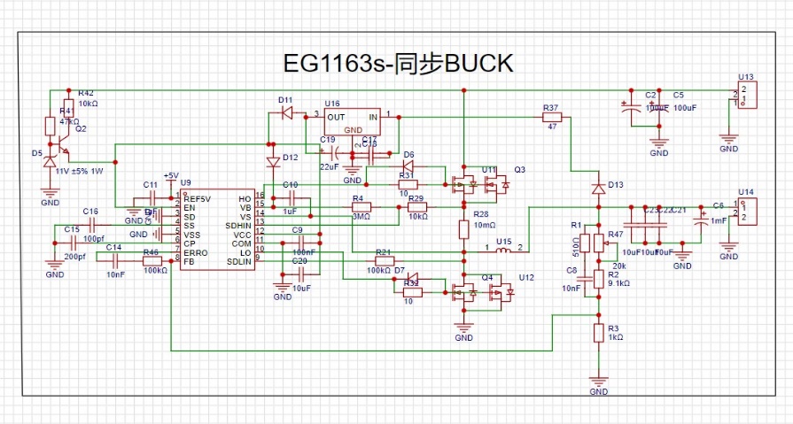
3.1.5 Synchronous Buck Circuit 4
3.1.6 Synchronous Boost Circuit 5
3.2 Program Design 5
3.2.1 Program Design Ideas 5
3.2.2 Program Flowchart 6
4. Test Scheme and Results 6
4.1 Test Scheme 6
4.2 Test Conditions and Instruments 7
4.2.1 Test Conditions 7
4.2.2 Test Instruments 7
4.3 Test Results and Analysis 7
4.3.1 Test Results 7
4.3.2 Test Result Analysis 7
Appendix 1 Detailed Parameter Test Results 8
Appendix 2 Physical Diagram in Operation 8
System Scheme Demonstration
Demonstration and Selection of Synchronous Rectification Module
Scheme 1: Using the freewheeling diode of a traditional asynchronous converter for rectification.
Scheme 2: Using MOSFETs for rectification.
Scheme Analysis: Scheme 1 has low power conversion efficiency and simple structure; Scheme 2 has high power conversion efficiency. Efficiency is prioritized, so this design adopts Scheme 2.
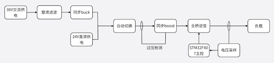
Boost Inverter Scheme Demonstration and Selection:
Scheme 1: Two boosters are used, one to boost AC-DC to 60V and the other to boost 24V DC to 48V. A relay switches the power supply to the bridge.
Scheme 2: The AC-DC voltage is first reduced to 24V, and a relay switches the power supply to the booster for uninterrupted operation. After boosting, the inverter is activated.
Scheme Analysis: Scheme 1 has a complex circuit and a relatively high 60V voltage, which is dangerous; Scheme 2 has a reliable circuit and a simple design. Therefore, Scheme 2 is adopted in this design.
Full-Bridge Inverter Circuit Demonstration and Selection : Scheme 1
: EG2104 is used as the gate driver.
Scheme 2: UCC27712 is used as the gate driver.
Scheme Analysis: Scheme 1 has weak driving capability and high MOSFET losses, resulting in low full-bridge efficiency; Scheme 2 reduces the MOSFET turn-on time to 100ns, significantly reducing MOSFET switching losses. Therefore, Scheme 2 is adopted in this design.
Signal Acquisition Circuit Scheme Demonstration and Selection:
Scheme 1: A voltage transformer and operational amplifier are used for precision rectification and voltage sampling.
Option 2: Use a voltage transformer and operational amplifier to boost the voltage for sampling.
Option Analysis: Option 1 requires both positive and negative power supplies; Option 2 only requires a 5V power supply. Option 2 is chosen for its DC power supply efficiency.
System Theoretical Analysis and Calculation
Theoretical Analysis:
Methods to Improve Efficiency
The internal losses of a switching power supply can be broadly categorized as: switching losses, conduction losses, additional losses, and resistive losses. Switching losses and conduction losses are the two most significant sources of loss in a typical switching power supply. A typical method to control these losses is to minimize the voltage drop during the power switch's conduction period. This involves using synchronous rectification technology to improve efficiency by 1%–6%; selecting switching transistors with lower on-resistance that meet requirements; ensuring the switching transistors operate in saturation and have sufficient driving capability; employing a lossless absorption circuit to eliminate spikes generated by parasitic components and return as much lost energy as possible to the power supply energy flow; and using iron-silicon-aluminum magnetic cores for the inductors to reduce iron losses.
Voltage Regulation Control Method
: The output voltage of the inverter is detected and fed back to the microcontroller. The PI algorithm processes the voltage, and the modulation of the SPWM in the inverter circuit is adjusted to achieve voltage regulation. The
selection
of the switching frequency
is crucial, as it significantly impacts the power consumption of the MOSFET. Higher frequencies result in greater losses. Lower operating frequencies reduce losses but increase output voltage ripple. Therefore, a lower frequency within the allowable range is chosen. A suitable switching frequency range is approximately 10kHz-60kHz. Our system uses a switching frequency of 20kHz to minimize losses.

Equation 2-1
typically takes 0.4-0.8 times the rated load and 0.04-0.1 times the switching frequency. In
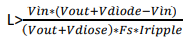
Equation 2-2,
Vin is 24V, Vout is 50V, and Vdiode is the on-state voltage difference of the synchronous rectifier MOSFET. At a current of 1A, this voltage is 40mV. The chip's oscillation capacitor is 270pF, so the frequency of Fs is 67kHz. Iripple is selected as 3A.
Circuit and Program Design
The circuit design
components are selected
from Equations 2-1 and 2-2: In the filter circuit, two 1mH inductors and one 5uF polypropylene film capacitor are chosen; in the boost circuit, the inductor is selected as 53uH, but here 68uH is used. Due to the skin effect of high-frequency current, Litz wire winding is chosen to effectively reduce inductor losses.
In the inverter circuit, the gate driver for the MOSFET is a UCC27712, which provides 2.8A sink current and 1.8A source current, and has interlock protection, significantly reducing the switching losses of the MOSFET. The MOSFET chosen is an IXTP56N15T with a withstand voltage of 150V, a maximum current of 56A, and an on-resistance of less than 36 milliohms. This MOSFET has the advantage of a low CISS (input capacitance of 2.2nF).
In the synchronous rectification circuit, a synchronous rectification MOSFET IPP200N15N3G is used, with a withstand voltage of 150V, a maximum current of 50A, and an on-resistance of 20 milliohms.
In the synchronous buck circuit, the AP70N100K MOSFET was selected. This MOSFET has a maximum withstand voltage of 100V and an internal resistance of only 7 milliohms, greatly reducing switching losses.
Figures 3-1

and 3-2 show that
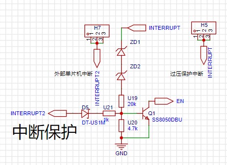
when the input voltage is higher than 48V, the two 24V
Zener diodes will reverse-biased and conduct,
pulling the EN pin low to ground through an NPN transistor, causing the chip
to stop working and thus protecting the subsequent circuitry. Figures 3-3,
3-4

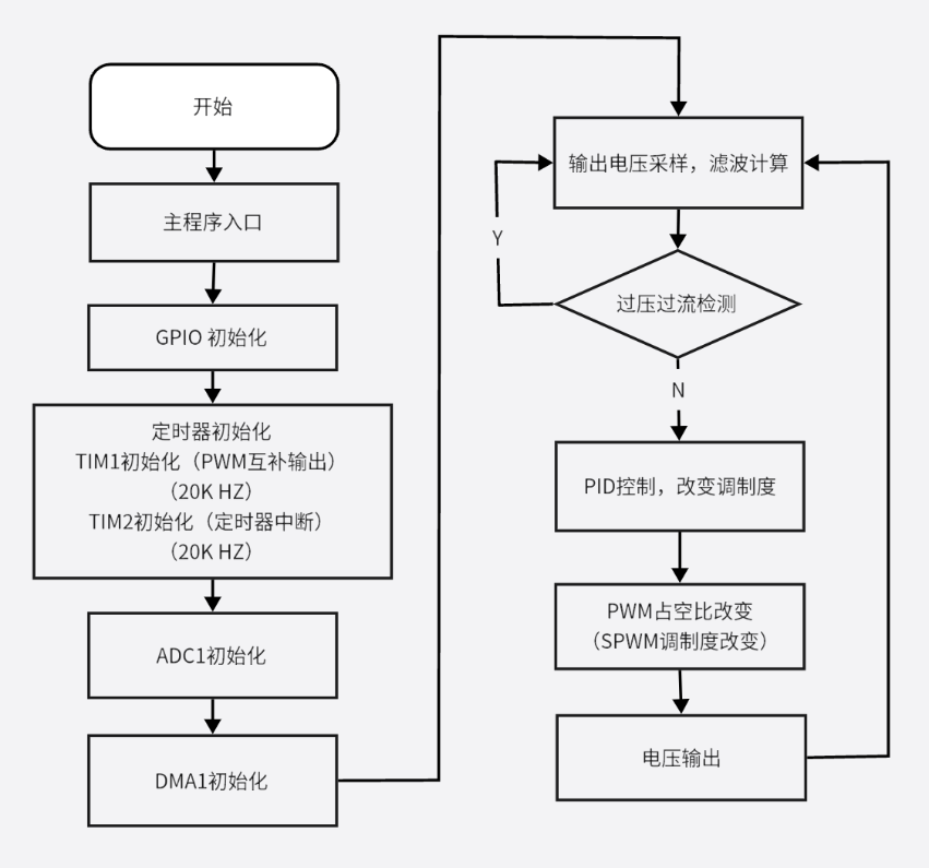
, and 3-5 show the program design. The main controller of this scheme is an
STM32F407VET6 . The TIM1 advanced timer generates two complementary PWM signals with dead time. TIM2 changes the duty cycle of the PWM to generate SPWM and changes the modulation degree. This SPWM controls the switching of the MOSFET to achieve DC-to-AC conversion, and the modulation degree can change the output voltage. To stabilize the output voltage at 30V, closed-loop control is required, with real-time monitoring and regulation of the output voltage. ADC1 samples the output voltage and transfers it via DMA, then uses a root mean square filter algorithm to obtain the output voltage. PI voltage stabilization is achieved by calculating the error between the actual output voltage and the target voltage value, and converting this error into an increment of the modulation index. An incremental PI algorithm is used to adjust the modulation index: when the output voltage is less than the target value, the modulation index is increased to raise the voltage; when the output voltage is greater than the target value, the modulation index is decreased to lower the voltage. Ultimately, the output voltage is stabilized at 30V, achieving the PI voltage stabilization function. Figure 3-6 shows the test scheme and results . Test Scheme 1) With an input AC voltage of 36V and a test output AC current of 1A, measure the AC voltage and frequency, and calculate the sinusoidal AC distortion (THD). The test results are shown in Table 4-1. 2) With an input sinusoidal AC voltage of 36V, change the load resistance to vary the output current from 0.1A to 1A, and test the output voltage. The test results are shown in Table 4-2. 3) Keeping the load constant at 30Ω, stabilize the output current at 1A, change the AC input voltage to vary it between 29V and 43V, and test the inverter output voltage. The test results are shown in Table 4-3. 4) Disconnect the AC power; the power supply automatically switches to DC. Simultaneously measure the AC voltage and frequency. The test results are shown in Table 4-4. 5) Disconnect the AC power; the power supply automatically switches to DC. Simultaneously test the input power and output power, and calculate the output efficiency. The test results are shown in Table 4-5. Test Conditions and Instruments : The hardware circuit and system schematic are completely identical and have been checked multiple times to ensure accuracy. The hardware circuit is guaranteed to be free of cold solder joints and short circuits, and includes overvoltage, overcurrent, and short circuit protection. Test Instruments : Multifunctional multimeter: VICTOR/VC9807A, CHNT/ZTY890D; Oscilloscope: Tektronix/TBS 1000C; DC regulated power supply: RIGOL/DP832; High-power resistor: 300.05Ω/500Ω adjustable ceramic tube resistor. Test Results and Analysis : Table 4-1 AC Power Supply THD Load Regulation SI Power Regulation SU DC Power Supply Efficiency η 0.788% 0.03% Detailed parameters are shown in Appendix 1. Test Result Analysis: This design is a single-phase uninterruptible UPS power supply with an STM32F407VET6 microcontroller as the control core and a full-bridge inverter circuit as the core circuit. It outputs a sinusoidal AC power frequency of 50Hz and a voltage of 30V. It can be powered by both DC and AC simultaneously. When the AC power fails, the DC power can be supplied promptly, with fast switching speed and an advanced control method. The power supply's load regulation is around 0.5%, indicating strong load-carrying capacity; the power regulation is less than 0.1%, indicating strong voltage regulation capability; and the power efficiency is above 85%. After multiple tests, the system's performance is reliable and stable, fully realizing all the functions required by the problem, and many indicators even exceed the requirements. Appendix 1 Detailed Parameter Test Results Table Appendix 2-1 Basic Parameters of AC Power Supply AC Input Voltage U1 Load Current I0 Output AC Voltage U0 Frequency Sine Distortion THD 36V 1A 30.00V 50.08HZ 0.788% Table Appendix 2-2 Load Regulation of AC Power Supply AC Input Voltage U1 Load Current I0 Output AC Voltage U0 Load Regulation SI 36V 0.1A 1A Table Appendix 2-3 Power Regulation of AC Power Supply AC Input Voltage U1 Load Current I0 Output AC Voltage U0 Power Regulation SU 29.06V 1A 30.01V 0.03% 33.01V 30.00V 36.01V 30.01V 40.06V 30.00V 43.01V 30.00V Table Appendix 2-4 Basic Parameters of DC Power Supply Input DC Voltage Ud Load Current I0 Output AC Voltage U0 Frequency 24V 1A
30.01V
50.09HZ
Table Appendix 2-5 DC Power Supply Efficiency
Input DC Voltage Ud
Input DC Current Id
Output AC Voltage U0
Load
Current I0 Input Power Wd
Output Power W0
Efficiency η
24V
1A

Figure Appendix 2-1


 京公网安备 11010802033920号

 B25671A4237A365


