Design Background:
The STM32H723ZGT6 is a high-performance microcontroller based on the Arm® Cortex®-M7 32-bit RISC core, operating at frequencies up to 550 MHz. It features 1 MByte of flash memory, 564 KB of RAM, and a rich set of peripherals and interfaces. It can meet the needs of various complex applications, such as industrial control, IoT, human-machine interaction, and audio/video processing.
To facilitate developers' rapid evaluation and use of the STM32H723ZGT6's functionality, a core board based on the STM32H723ZGT6 was designed. It integrates basic power supply, clock, reset, download, and debugging circuits, while providing various expansion interfaces such as USB, SDIO, SPI, I2C, UART, LCD, and DCMI, enabling connection and communication with various peripheral modules and sensors. This core board employs a four-layer design and lead-free soldering technology to ensure circuit stability and reliability.
The purpose of this design is to demonstrate the performance and features of the STM32H723ZGT6, as well as the usage methods and precautions of the core board, helping developers quickly get started with the development and application of the STM32H723ZGT6.
Requirements analysis:
A TFT screen is used to display and store images captured by the camera, as well as monitor and control the system status.
An SROM is used to store and manage system programs and data, improving system speed and stability.
An SD card is used for image data backup and transmission, as well as system parameter configuration and updates.
External Flash memory is used to store and manage more image data, increasing the system's storage capacity and flexibility.
An OV2640 camera module is used for real-time environmental monitoring and photography, as well as image quality adjustment and optimization.
The system supports multi-task concurrency and has an efficient task scheduling and resource management mechanism.
The system provides a user-friendly interface with clear display and operation prompts.
The system supports multiple protocols and standards, exhibiting good compatibility and scalability.
Rapid solution verification is also included.
The
hardware system architecture
of this design includes an STM32H723ZGT6 microcontroller minimum system, a JTAG download interface, SD card file read/write, SRAM static random access memory, a TFT LCD screen, Flash memory, serial communication, power supply, USB connector, and I/O expansion.

Figure 3.1 shows the hardware system architecture . The STM32H723ZGT6 microcontroller
minimum
system refers to the necessary components for the microcontroller to function properly, generally including four parts: power supply circuit, clock circuit, reset circuit, and download/debug circuit. This design uses an LQFP144-pin main control chip, and some peripheral circuits are shown in Figure 3.2.

Figure 3.2 STM32H723ZGT6 Pin Assignment Diagram

Figure 3.3 STM32H723ZGT6 Physical Diagram
3.2.1 Power Supply Circuit The
input voltage is provided by a 5V power supply from the USB or I/O expansion port, which is then converted to 3.3V by the AMS117-3.3 linear regulator chip to power the microcontroller.
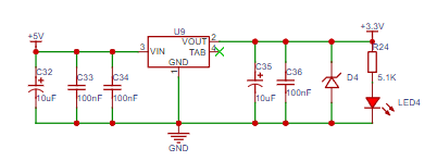
Figure 3.4 DC5V to 3.3V Diagram
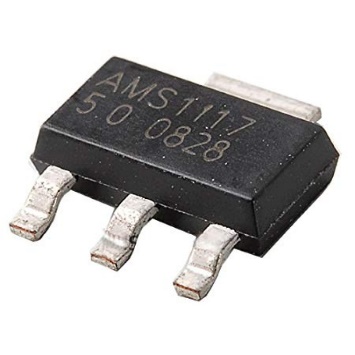
Figure 3.5 AMS117-3.3 Physical Diagram
3.2.2 ADC/DAC Voltage Reference Circuit The
ADC/DAC is used for analog signal acquisition, and the precision of its reference power supply directly affects the accuracy of the microcontroller's analog signal acquisition and output. The STM32H723ZGT6 is a 16-bit high-precision analog signal acquisition device. This means it can provide very accurate analog signal acquisition. In this design, an adjustable reference provided on the board can be selected, which uses a TL431 to change its output voltage by changing its feedback point. Alternatively, a more precise reference voltage can be connected externally via the I/O expansion interface, determined by the selection resistor U7.
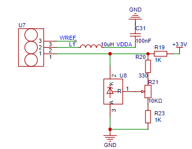
Figure 3.6 Analog Reference Circuit Diagram
3.2.3 Program Execution Selection Circuit The
microcontroller program execution location is determined by SW1. When SW1 is pressed, Q1 and Q2 are turned on, the BOOT0 pin voltage is pulled high, and the NRST pin is pulled low to trigger a reset, allowing the microcontroller to execute the program externally. When SW1 is not pressed, the voltage is pulled low, and the microcontroller executes the program internally. When SW2 is pressed, the NRST pin is pulled low to trigger a reset.
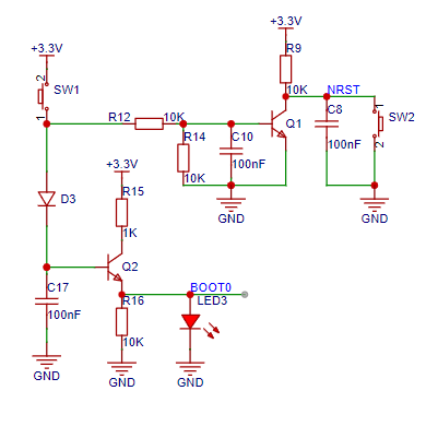
Figure 3.7 Program Executor Selection Circuit Diagram
3.2.4 Crystal Oscillator Filtering Circuit
In this design, the hardware system provides an external 25MHz system clock and a 32.768kHz RTC clock crystal to provide a precise clock frequency. To ensure stable microcontroller operation and a certain level of anti-interference capability, multiple 0.1uF capacitors are provided at the external voltage interface to ensure a smooth system operating voltage.
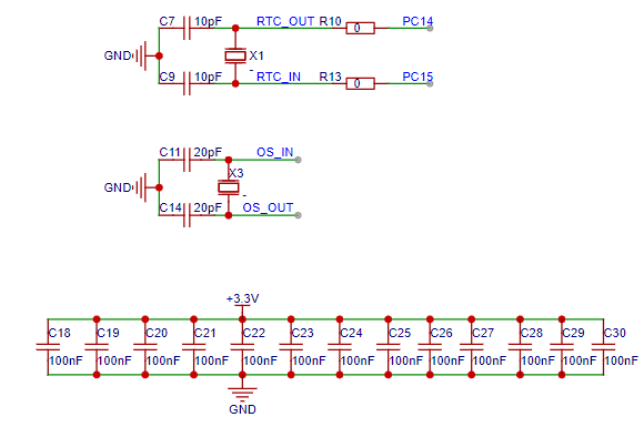
Figure 3.8 Crystal Oscillator Filtering Circuit
3.2.5 Download/Debugging Circuit
In this design, the download interface reserves 2*10P horn-shaped sockets, which can be used with Jlik, DAP, STlink downloaders or for debugging the microcontroller.

Figure 3.9 Download/Debugging Circuit Diagram
SRAM Static
Random-Access Memory Circuit Static Random-Access Memory (SRAM) is a type of random access memory. The term "static" means that as long as this type of memory is powered on, the data stored in it can be constantly maintained. In contrast, the data stored in Dynamic Random-Access Memory (DRAM) needs to be updated periodically. 18 address bits and 16 data interfaces are reserved to achieve high-speed read and write.

Figure 3.10 SRAM Static Random-Access Memory Circuit Diagram
TFT LCD Display Interface
The TFT LCD screen interface is the interface connecting the LCD screen assembly to the motherboard (also known as the signal processing board or signal board), i.e., the signal input interface of the logic board. The TFT interface uses the Zhengdian Atom interface; please refer to the Zhengdian Atom official website for details.

Figure 3.11 TFT Interface Circuit Diagram
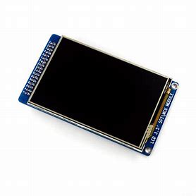
Figure 3.12 TFT Physical Diagram
Serial Communication Circuit The serial
communication uses CH340E as the data conversion chip. Since it is connected to the host computer for communication, its peripheral circuit is very simple.
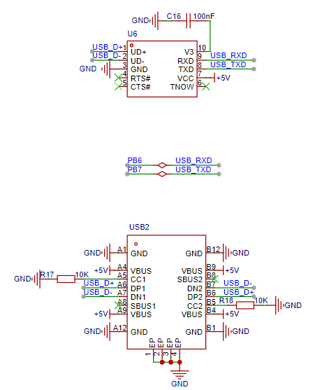
Figure 3.13 Serial Communication Circuit Diagram
The camera driver circuit
The DVP interface of the OV2640 chip itself has 10 data lines and can output 10 bits of RAW data. However, in most cases, we use eight bits of data. Therefore, only the high 8 bits of data of the DVP output interface are needed. Therefore, only D[9:2] is retained and mapped to interface OV-D0-7. The OV_SCL and OV_SDA of the above circuit are not connected to physical pull-up resistors. Direct use will cause problems. Therefore, the microcontroller's IO chip pull-up resistors must be enabled in the pin configuration of Quartus II software for these two places to be used normally.
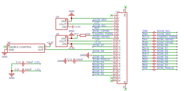
Figure 3.14 Camera Driver Circuit Diagram
Results and Phenomena
Soldering and Debugging
The smallest components on the entire circuit board are 0603 packaged components, so the soldering difficulty is not too high, and the components are relatively evenly distributed. It is recommended to solder the main control chip and SRAM first to experience the pleasure of solder dragging.

4.1 Front view of PCBA after soldering

4.2 Back view of PCBA after soldering
The
overall appearance is quite perfect. In terms of software, there are relatively few resources for H723ZGT6 online. Most HAL libraries are not fully developed in their official underlying layers and have many bugs.

CubeMAX version 6.10 is used.
The test code is attached. The camera driver is incomplete and data needs further investigation.

Power-on physical picture


 京公网安备 11010802033920号

 AD404M48VQA-5


