Project Description:
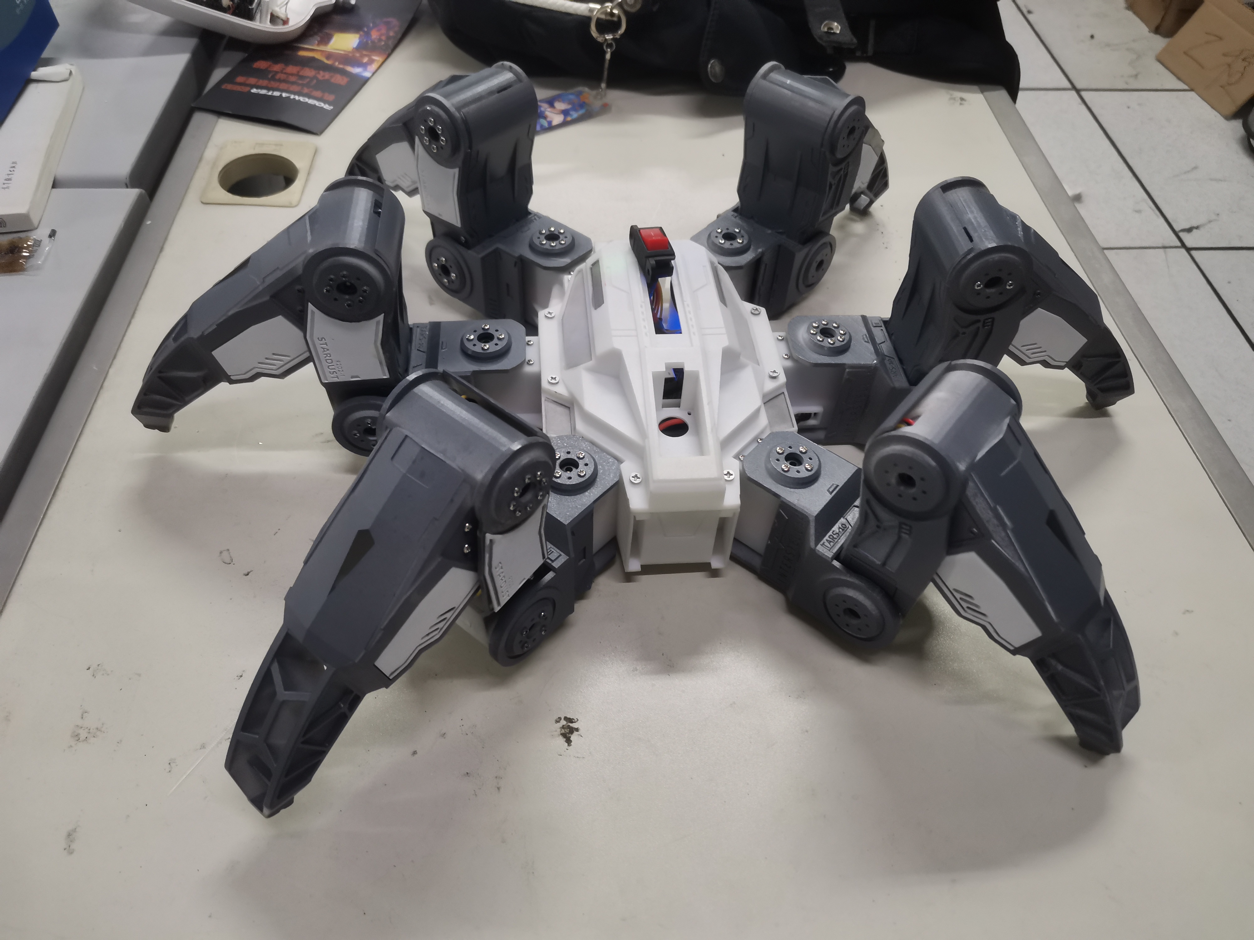
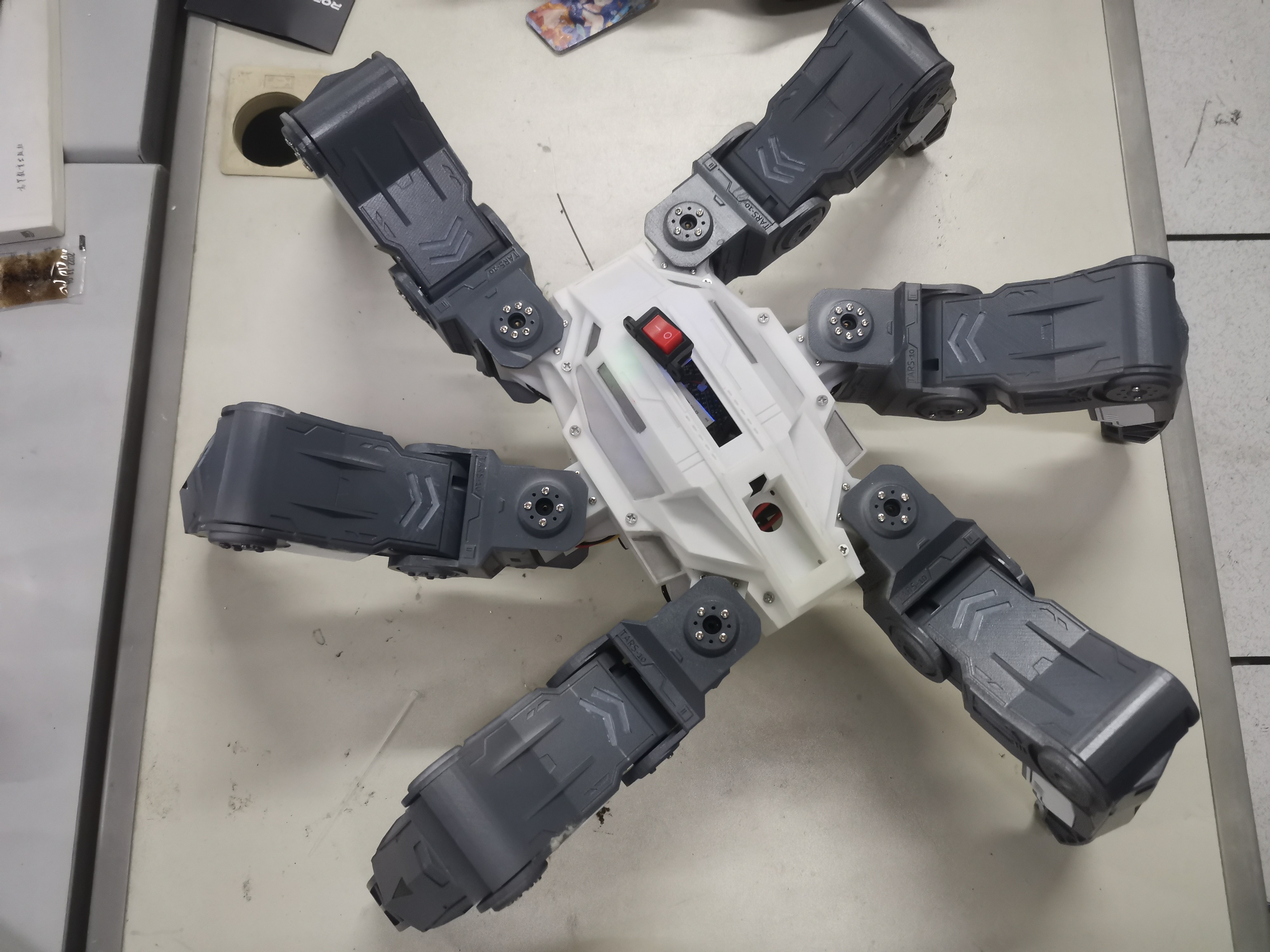
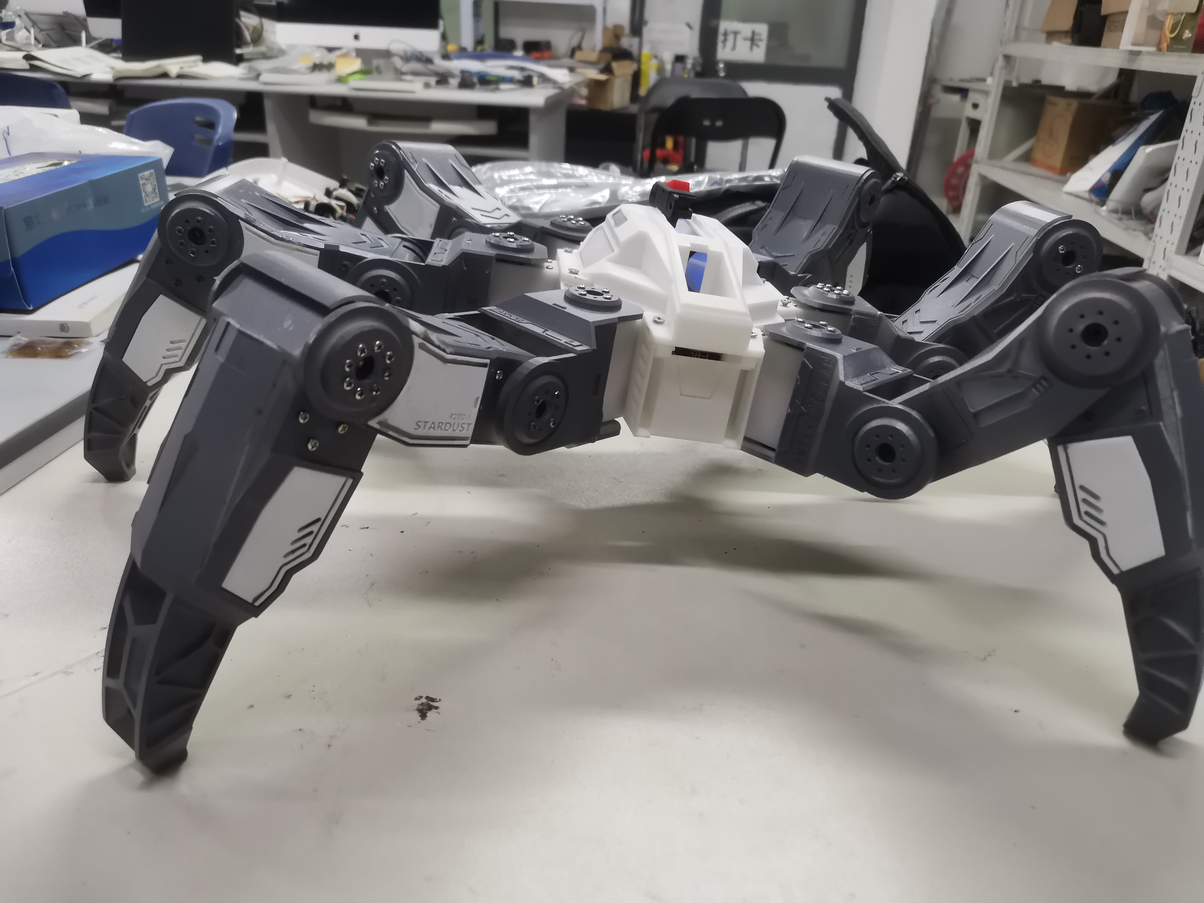
This is my undergraduate graduation project, a hexapod robot that uses real-time kinematics calculation for movement. An
updated
robotic arm has been added for gripping objects.
Overall structure diagram.

Open source license:
GPL 3.0.
Project Functions:
1. Control the robot's movement via remote control.
2. Control the robot's posture and position
. 3. Control the direction of movement and turning angle (which can be understood as linear velocity and angular velocity)
. 4. Move flexibly while controlling the robot's position and posture.
5. Move even under different robot positions and postures .
Project Attributes:
This project is being publicly released for the first time and is my original work. It has not won any awards in other competitions. The project
is
basically complete.
Software Description
: Note: The software can use nested code blocks. Only the important parts need to be described, not all of them.

Hardware Selection:
Main Control Unit Selection:
Robot motion calculation requires high floating-point arithmetic capabilities. For smoother movement, more computing power is needed. Therefore, this hexapod robot uses the high-performance STM32H750VBT6, which supports FPU.
The STM32H750VBT6 uses a 32-bit ARM Cortex-M7 core, featuring a double-precision floating-point FPU, 16KB of data cache, and 16KB of instruction cache. Its clock speed reaches 480MHz, and can be overclocked to 600MHz.
The core board uses the STM32H750VBT6 mini core board designed by WeActStudio. This core board integrates 8MB of Quad SPI Flash and 8MB of SPI Flash, providing ample space for storing robot control code. The core board provides an SD card and Type-C interface, offering strong expandability. A diode is also connected in series to prevent backflow. The operating voltage is 3.3V to 5V.
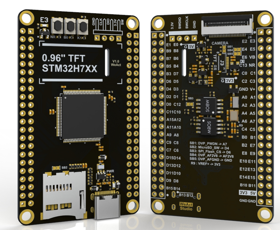
Because the STM32H750VBT6 has limited on-chip Flash memory (only 128kb), there's not much space left after installing FreeRTOS. Therefore, it's typically necessary to write the main code to external Flash and the BootLoader program to the on-chip Flash. The BootLoader then jumps to the main code stored in the external Flash.
Servo selection:
To simplify wiring and reduce the failure rate, the Huaner LX224 serial bus servo is used. The servo's rotation accuracy is 0.24°, and its torque is 20kg·cm (approximately 1.98N·m).

Power supply selection:
Due to the hexapod robot's weight and high power requirements for movement, a high-power model aircraft battery with strong discharge capacity is selected.

Remote control receiver:
The DJI DR16 remote control receiver is used. The DR16 has a long remote control distance and strong anti-interference capabilities. Because it uses DBUS levels, which are opposite to serial port levels, the logic levels need to be inverted when configuring the serial port. The DR16, based on 2.4G wireless transmission, features power saving, longer transmission distance, and greater bandwidth, enabling long-distance control of hexapod robots and meeting the needs of legged robots working in complex environments. It operates at 5V

.
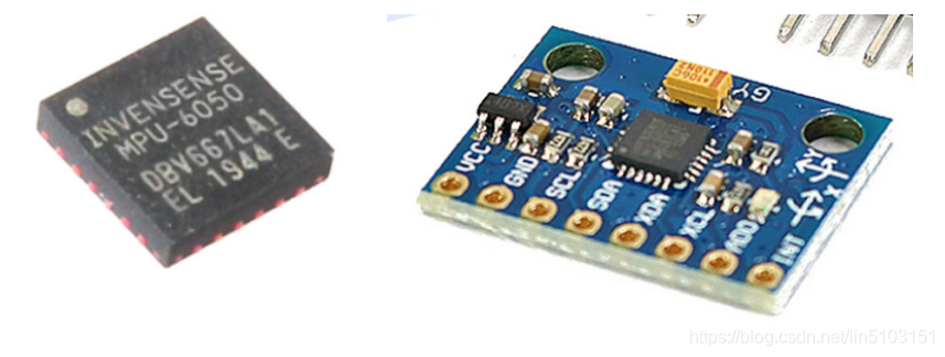
The gyroscope uses an MPU6050 module, a 6-axis motion processing component from InvenSense. Internally, it integrates a 3-axis gyroscope and a 3-axis accelerometer, communicating with external devices via an IIC interface and featuring a built-in Digital Motion Processor (DMP). The DMP significantly reduces the computational burden on the microcontroller and is widely used in model aircraft and other products. Its operating voltage ranges from 3.3V to 5V.
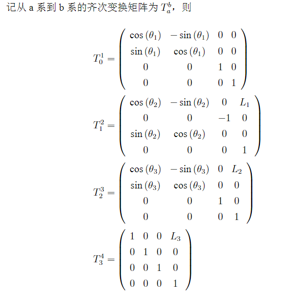
Kinematic modeling
is the core algorithm of this robot, so I will briefly explain some of the algorithm steps here. This requires a certain foundation in robotics; those without a background or who are not interested in this part can skip it.
The kinematic analysis of a hexapod robot is to establish a spatial rectangular coordinate system on the joints of the robot's legs, transform the relationship between the distance between the joints and the angle between the joints, solve the position and attitude matrix, and thus establish the kinematic equations of the robot. In order to determine the relationship between the coordinate systems on each joint, a suitable method is needed for kinematic analysis. This paper uses the DH modeling method, which uses the second transformation matrix to describe the spatial relationship between the links on the robotic arm. Each joint can be represented by a fourth-order homogeneous transformation matrix. The second transformation matrix is multiplied according to the link order to obtain the relationship between the head and tail coordinate systems and construct a kinematic coordinate system.
First, the single leg is modeled
with the leg as the origin, as shown in the figure below. The spatial rectangular coordinate system is established with the starting end of the leg as the origin.
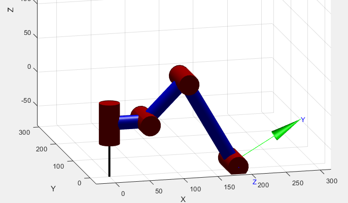
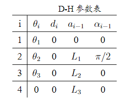
The modeling method uses the D-H modeling method, which is mainly applied to robot kinematics. A coordinate system is established on each link. The coordinate transformation between the two links is realized through homogeneous coordinate transformation. The relationship between the head and tail coordinate systems can be established by using the second coordinate transformation multiple times [3]. A kinematic coordinate system can be constructed by using the DH modeling method. Let the leg's starting end be system 0, "starting end servo 1" be system 1, "servo 1 + servo 2" be system 2, "servo 2 + servo 3" be system 3, and "servo 3 + leg end" be system 4. Let the axis distance between servo 1 and servo 2 be L1, the axis distance between servo 2 and servo 3 be L2, and the axis distance between servo 3 and the leg end be L3. Then the DH parameters are shown in the table below.
Forward kinematics calculation:


Inverse kinematics calculation:
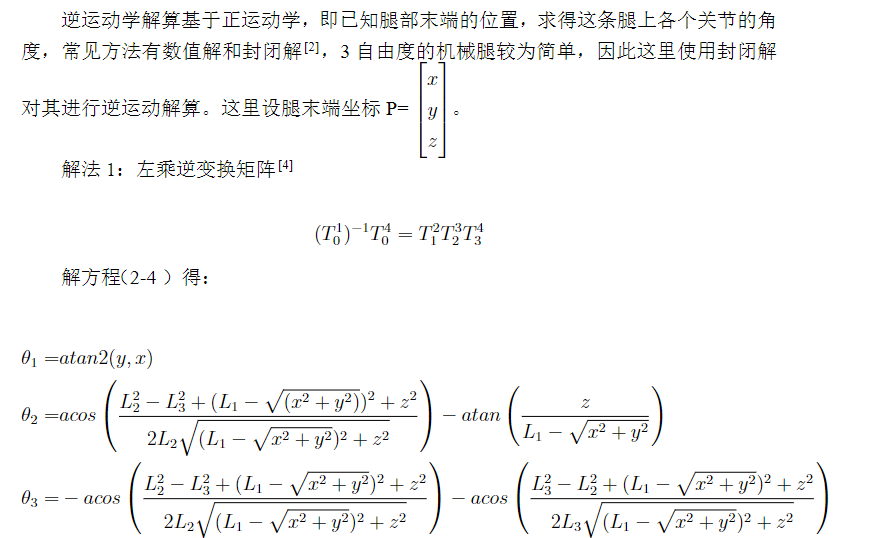
Forward and inverse kinematics calculations are performed throughout the entire robot motion algorithm. After completing gait planning, forward and inverse kinematics calculations are performed to solve for the positions of the 18 servos on the body.
Those interested in gait algorithms and position and attitude control can find information in my graduation thesis.
Physical demonstration of
fuselage position control:
(1) Control height (z-axis)
(2) Control y-axis and x-axis

Fuselage attitude control:
(1) Control Z-axis
(2) Control Y-axis
(3) Control X-axis

Design notes
No
other
video links
https://www.bilibili.com/video/BV1xg4y1L7wh/
Project attachment:
https://github.com/ByteRyze/Hexapod_2


 京公网安备 11010802033920号

 HY57V651620B


