Project Description:
This project aims to design a high-performance, multi-functional DDS-function waveform generator
to achieve basic project functions while offering strong modular expandability.
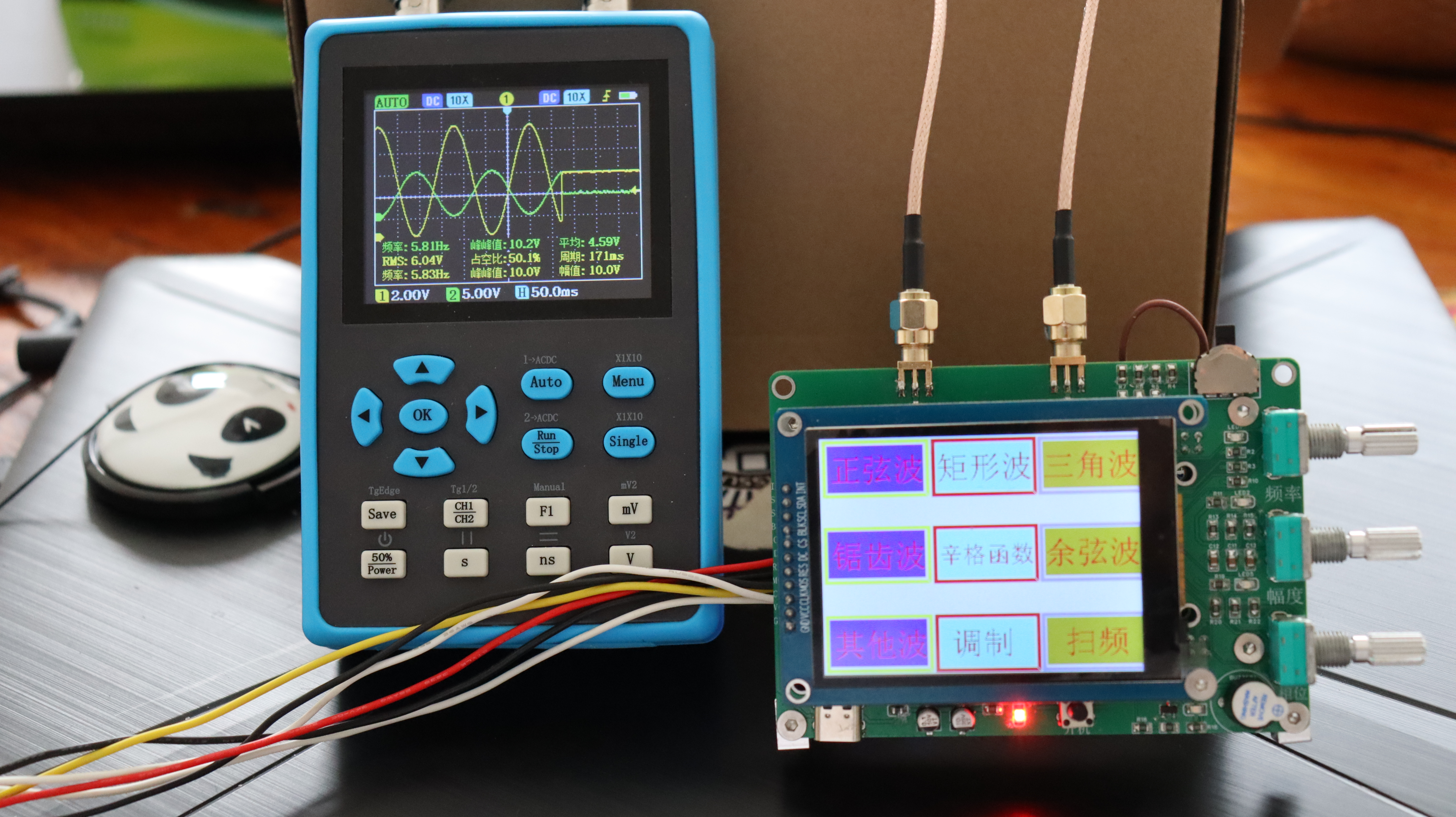
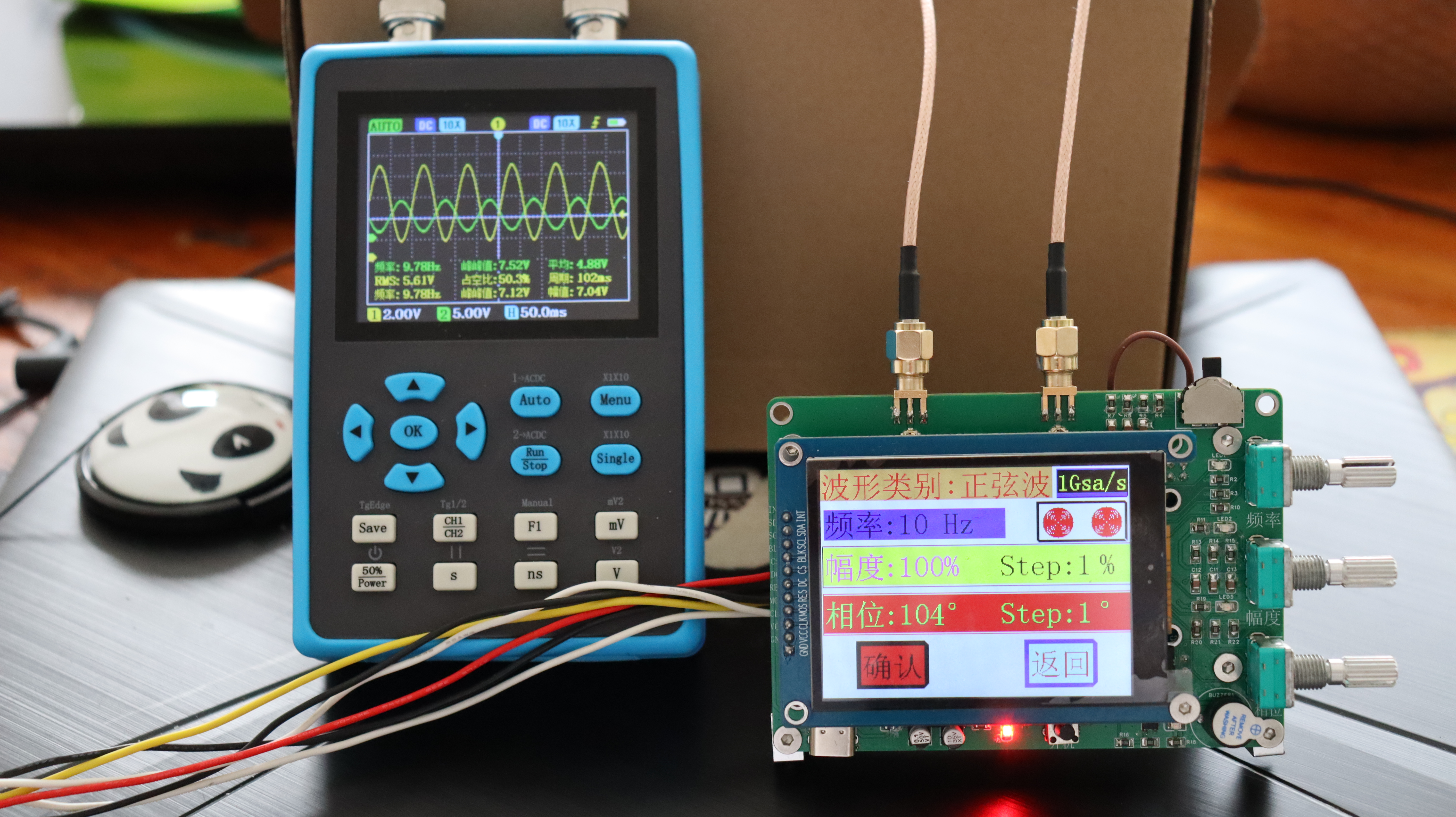
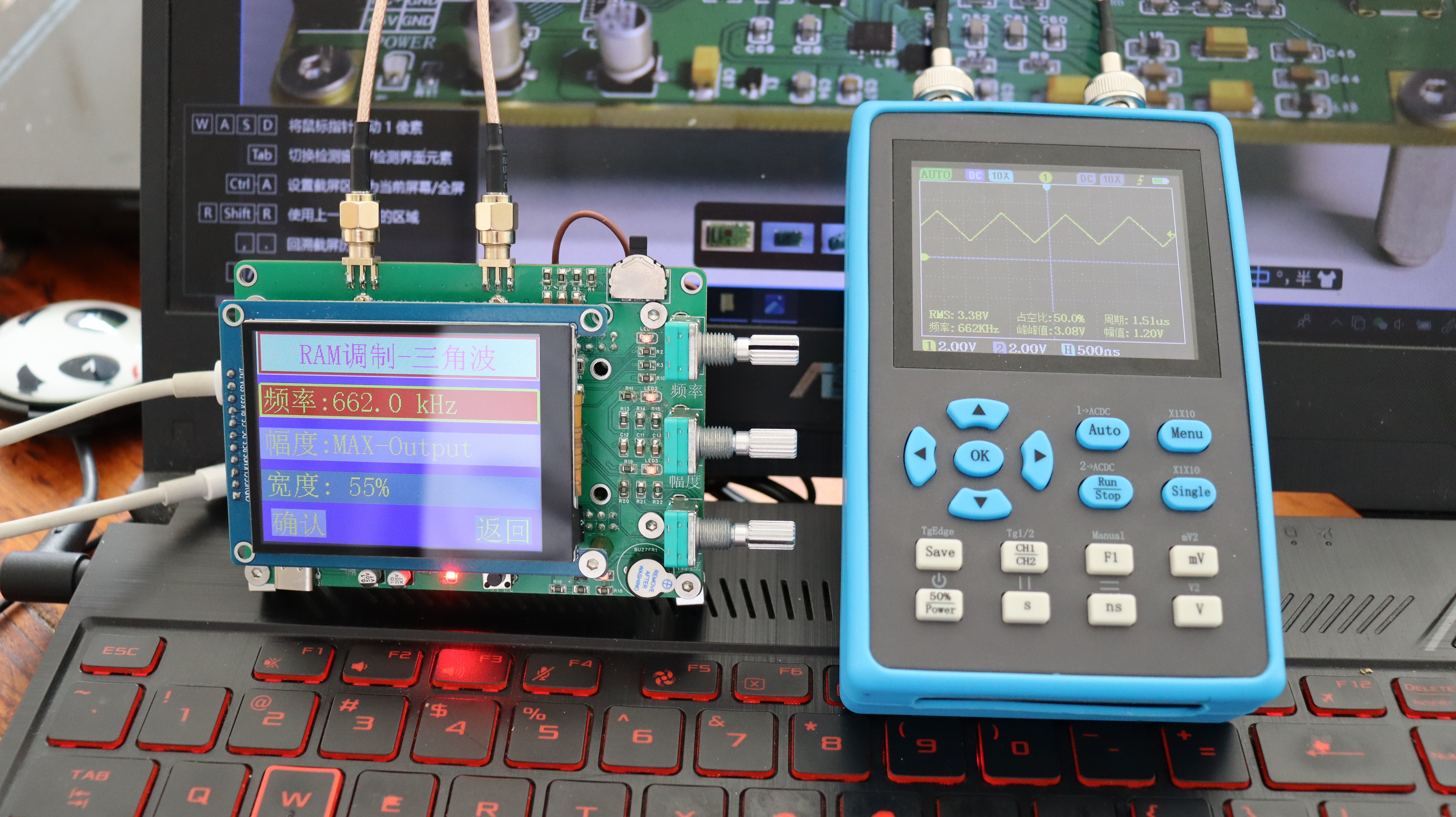
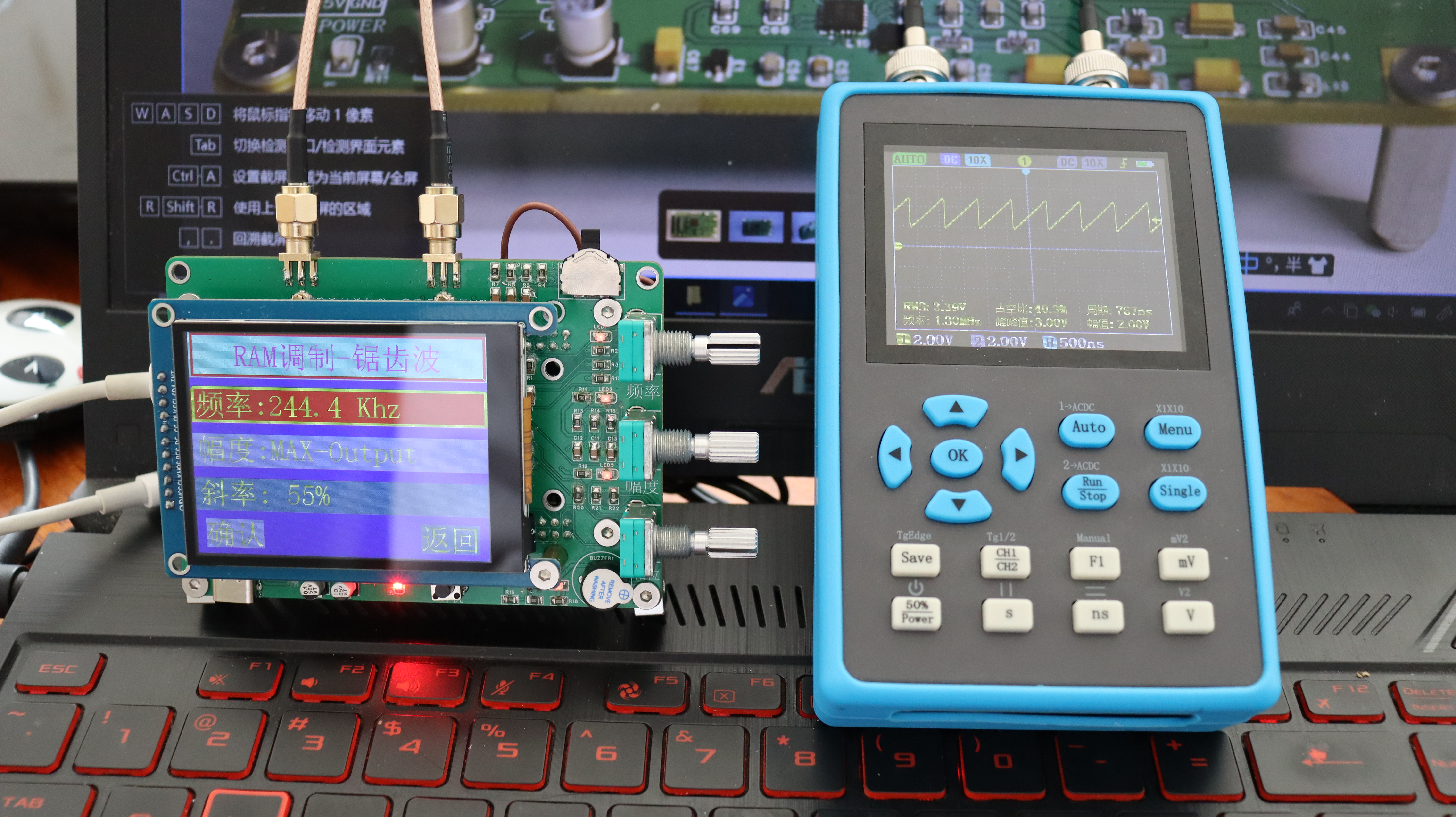
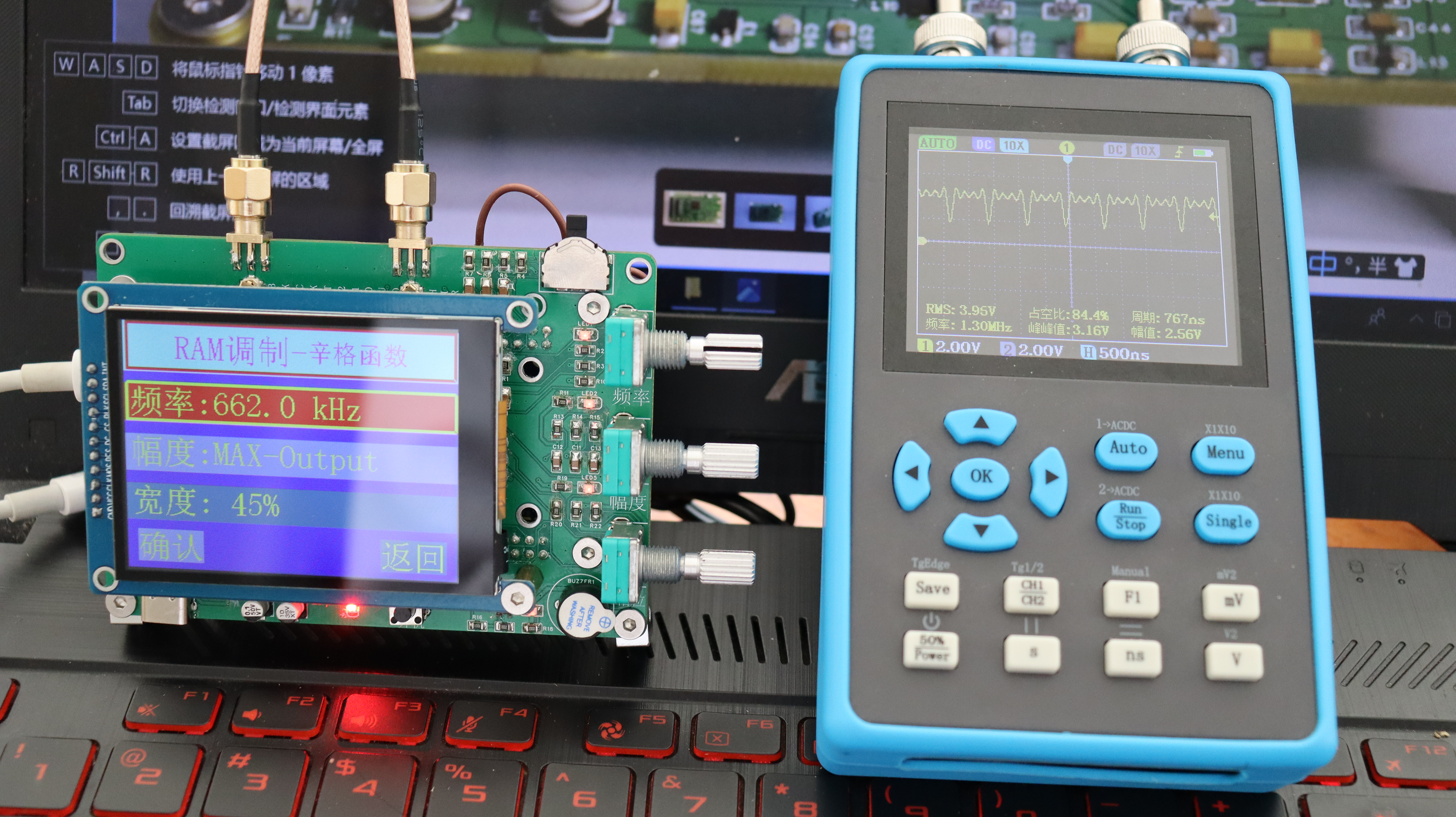
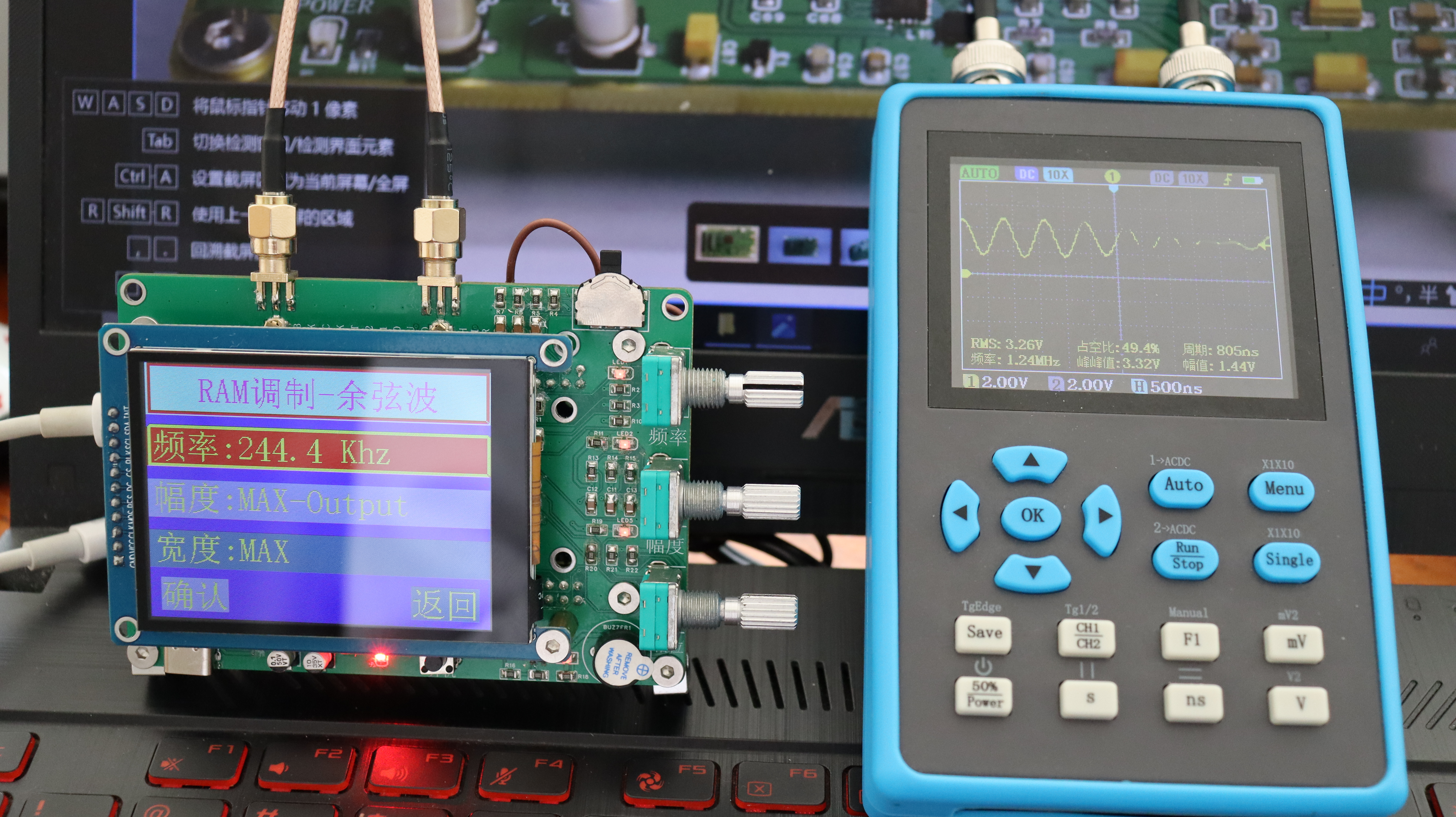
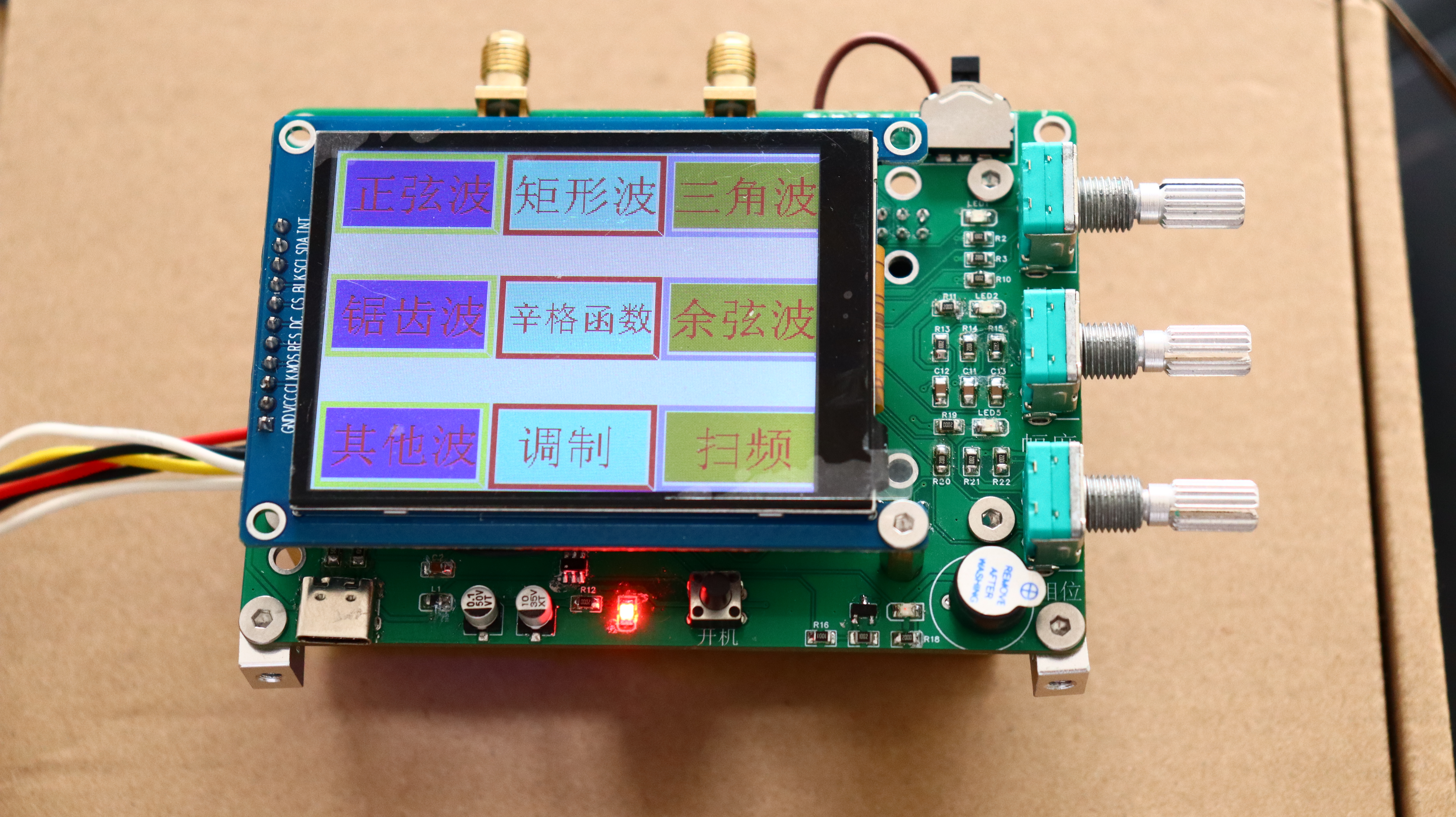
The basic functions of this design are: to output sine, triangle, square, and arbitrary waves, with adjustable waveform amplitude and frequency. An OLED display is used to show waveform parameters, output status, and waveform selection. For detailed functionalities, please refer to the demonstration video.
The
core of the system's waveform generation is the AD9910, primarily used to generate triangle, square, and other arbitrary waveforms. No other peripheral circuitry is required besides the filtering circuit. The system control core is an STM32F407ZG, and the display is a 2.8-inch OLED touchscreen. Waveform parameters are adjusted via three EC11 horizontal encoders.
Furthermore, high-frequency circuitry typically employs immersion gold plating, metal edging, and multi-layer board designs. This design utilizes all of these. In actual development, to reduce costs, a double-layer board design is often used. Therefore, the actual project requirements will depend on cost constraints.
It's important to note that DDS chips are generally very expensive; for example, AD9910 and AD9959 are both around 200 RMB. A cost-saving method is to use salvaged chips, which cost only a few tens of RMB and can significantly reduce costs!
Project-related functions:
Based on the AD9959 and AD9910 modules, the following basic functions will be implemented:
1. Frequency, amplitude, and phase control for signals from 10Hz to 4200MHz.
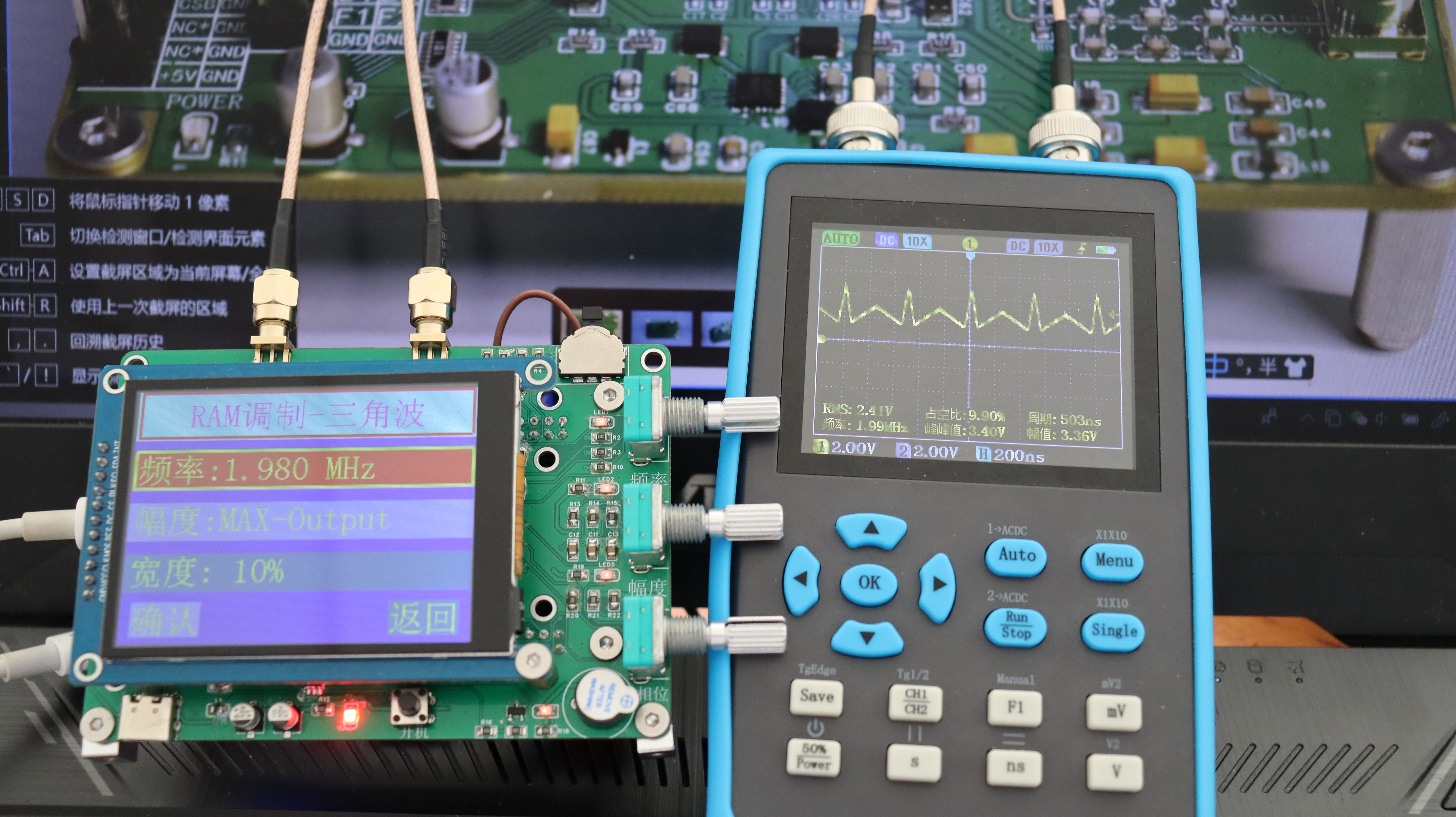
2. Triangular wave output.
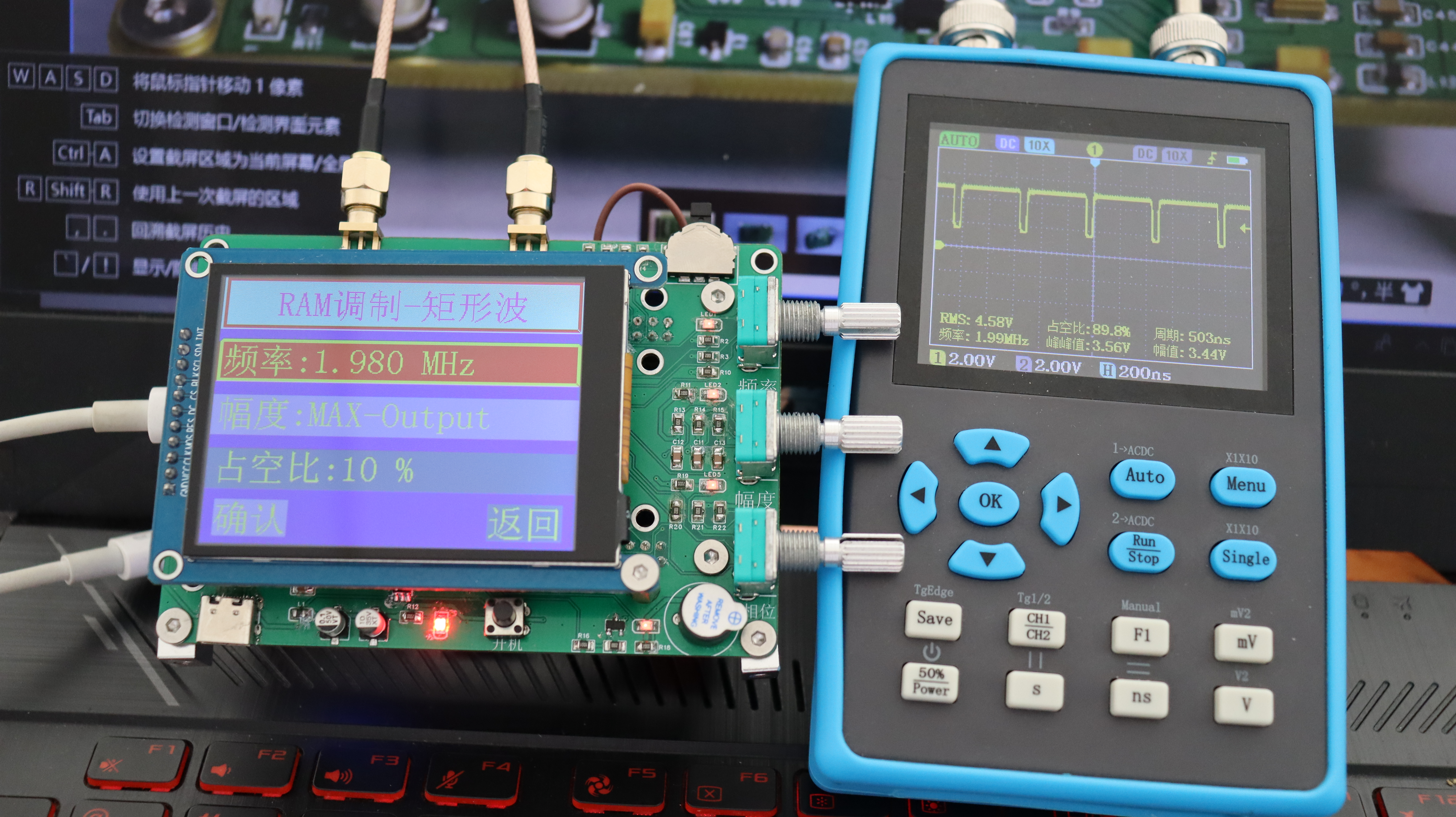
3. Square wave output.
4. Arbitrary wave output.
5. Adjustable waveform output frequency and amplitude.
Note: Please refer to the demonstration video for specific functional details.
Project attributes:
This project is being publicly disclosed for the first time and is my original work. This project has not won any awards in other competitions.
Project progress
: October 1, 2023 – Current progress: AD9959 module design completed; waveform output debugging completed and waveform output meets expectations.
October 19, 2023 – Current progress: AD9910 module design completed; awaiting board delivery for testing.
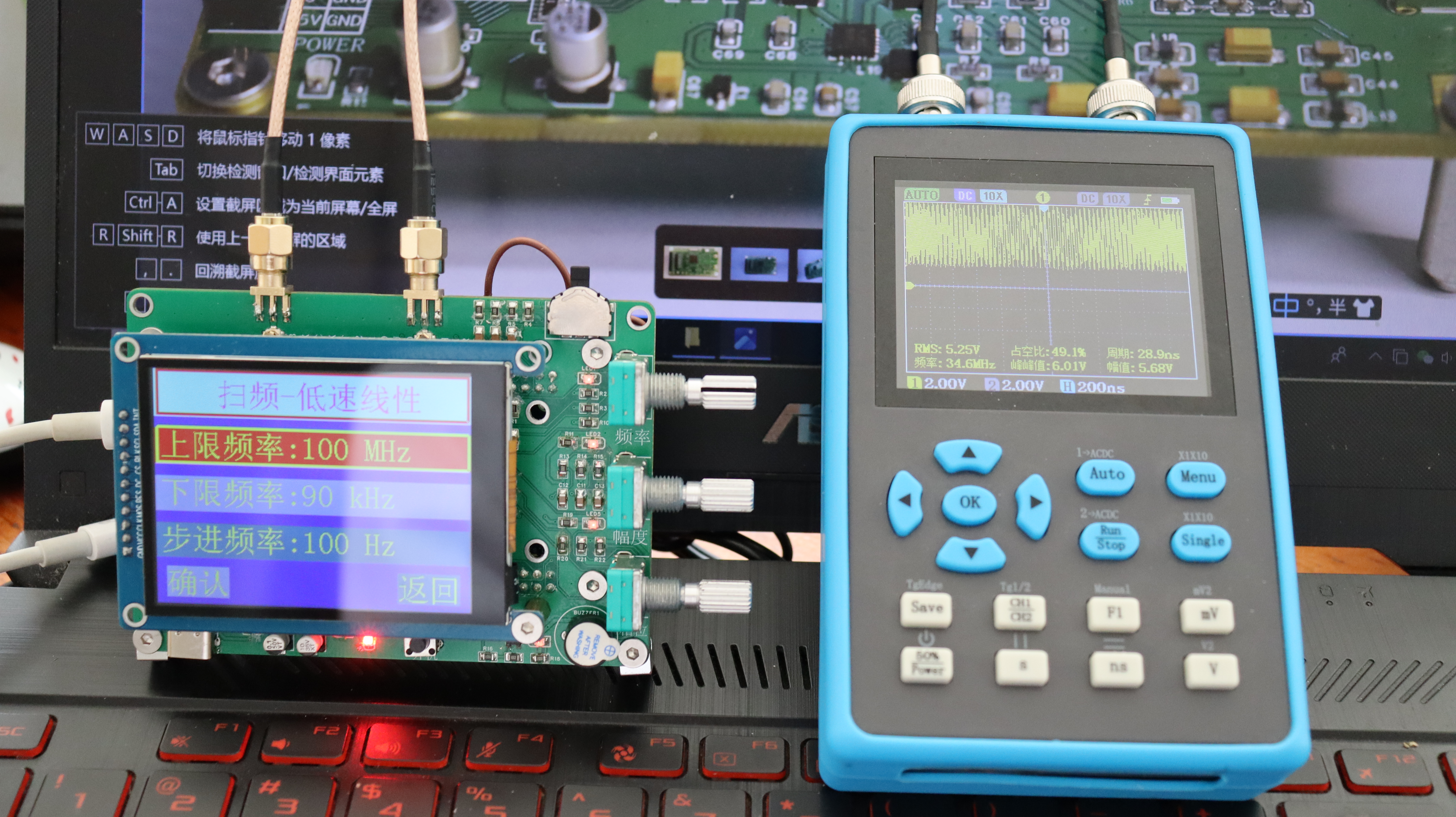
Time: 2023.10.25 ---- Current Progress: Testing AD9910 Performance
Time: 2023.11.19 ---- Current Progress: Testing Completed.
Functional Demonstration Screenshots:

Design Principles
I. AD9959 Schematic Design Description
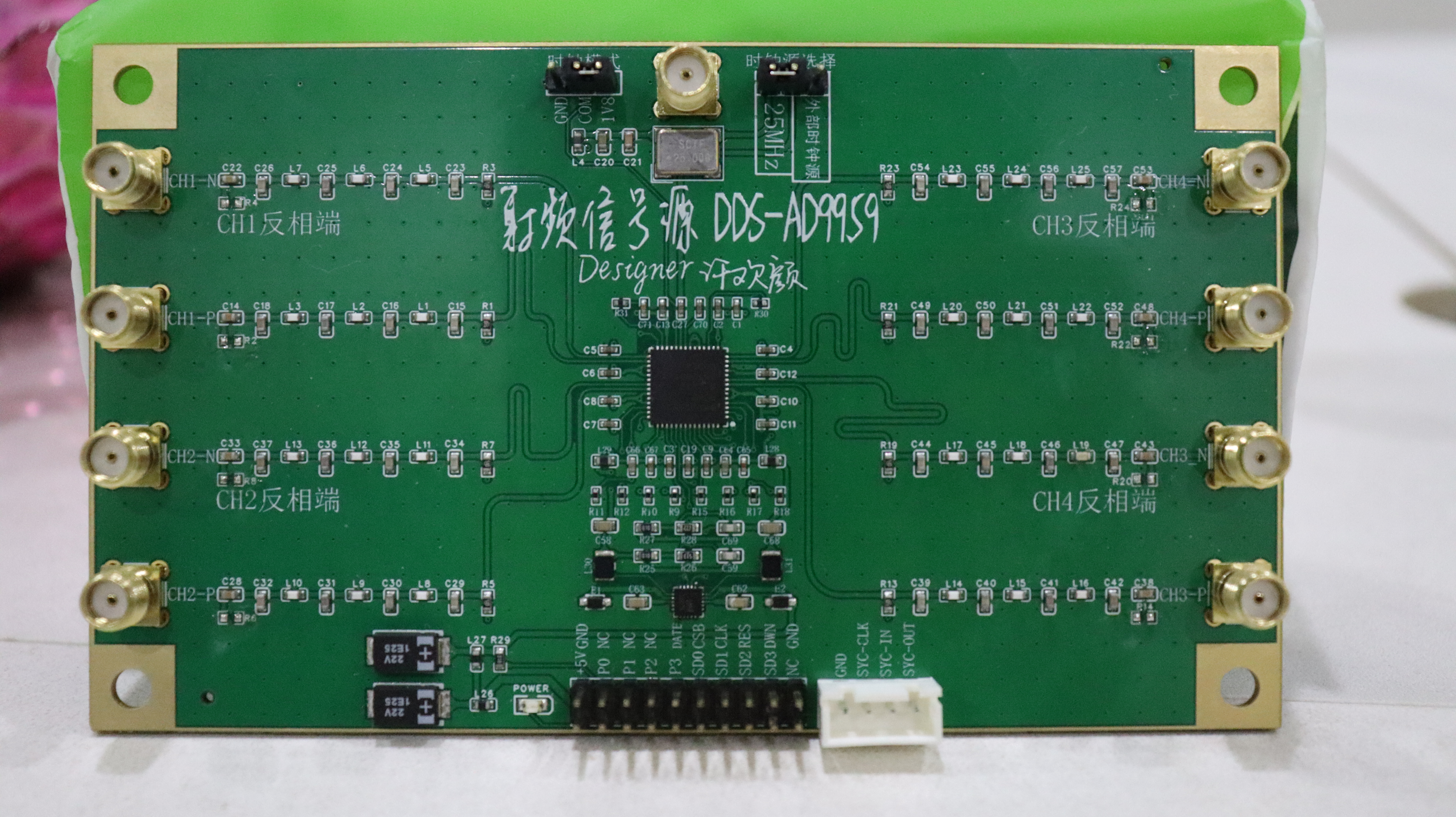
The AD9959 datasheet is in English, and I did not read the details carefully. High-frequency circuits have high requirements for power supply filtering and isolation, which is very important. The circuit design references some typical schematic diagrams, expanding from 4 outputs to 8 outputs because each output of the AD9959 has an additional inverted waveform for verification. In the AD9959, the filtering circuit is mainly implemented through ferrite beads, and the circuit structure is shown in the figure.

The power supply circuits used on Taobao are generally AMS1117 series LDO chips. These LDOs tend to overheat during 1.8V power conversion. In this design, the TMI1007B is used instead. The circuit structure is as follows, and actual verification shows that it can greatly reduce the problem of overheating. However, one of the two PCBA circuits produced by SMT is unusable, most likely because the purchased chip is of poor quality! When purchasing this on Taobao, you should be more cautious.

I. AD9910 Schematic Design Instructions:
When designing the AD9910 schematic, the datasheet has a Chinese version. Therefore, the circuit design should refer to the Chinese version. For the power supply design, follow the power supply grouping principles mentioned above. Please refer to the schematic design for details; further explanation is not provided here.
Software Instructions:
Matlab code for generating arbitrary waveforms. The following screenshots show the arbitrary waveforms generated using Matlab.
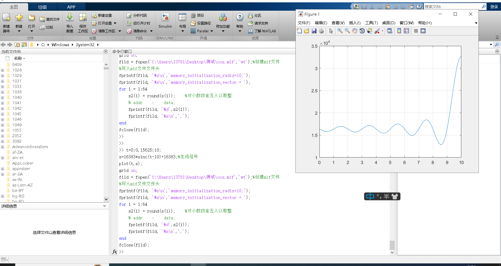
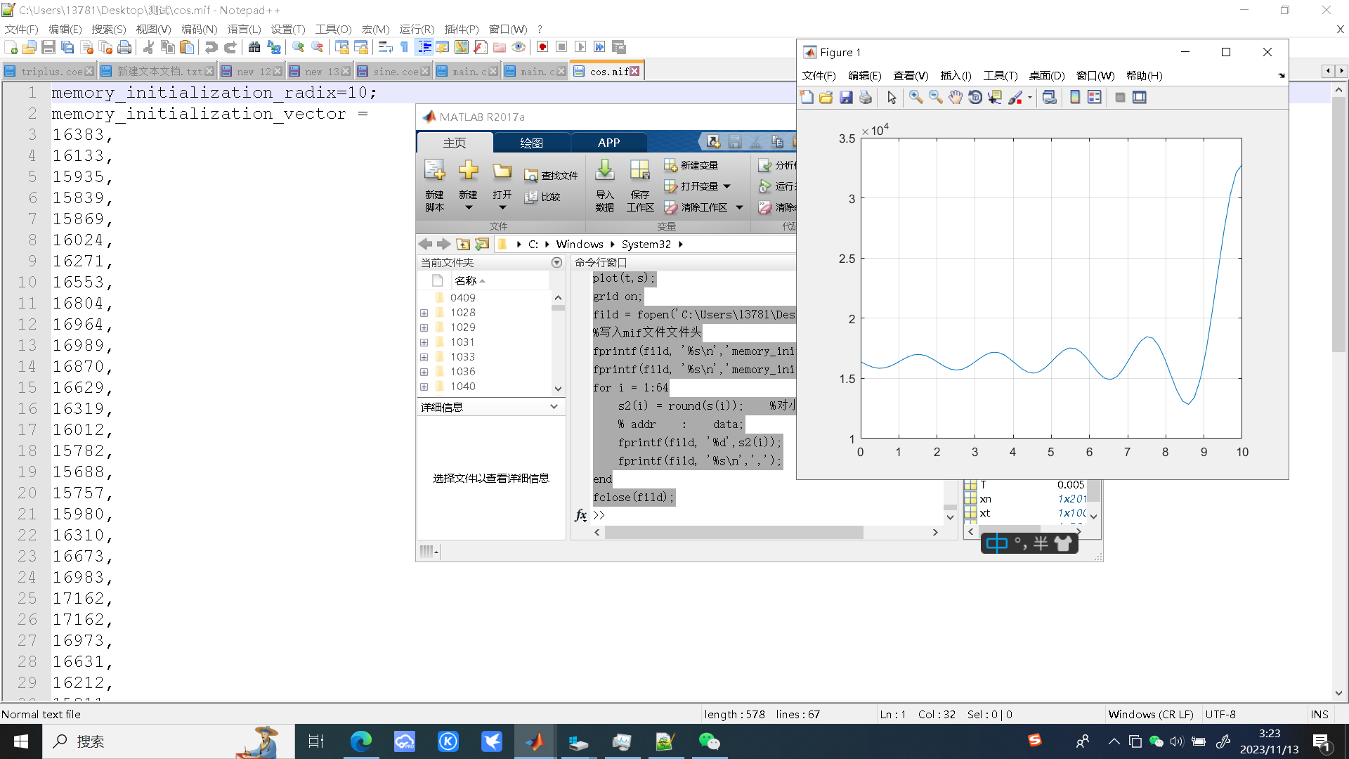
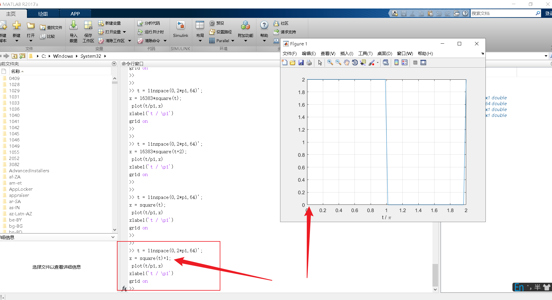


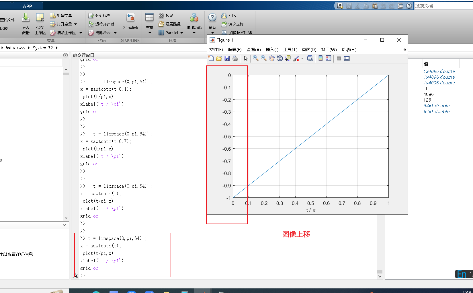

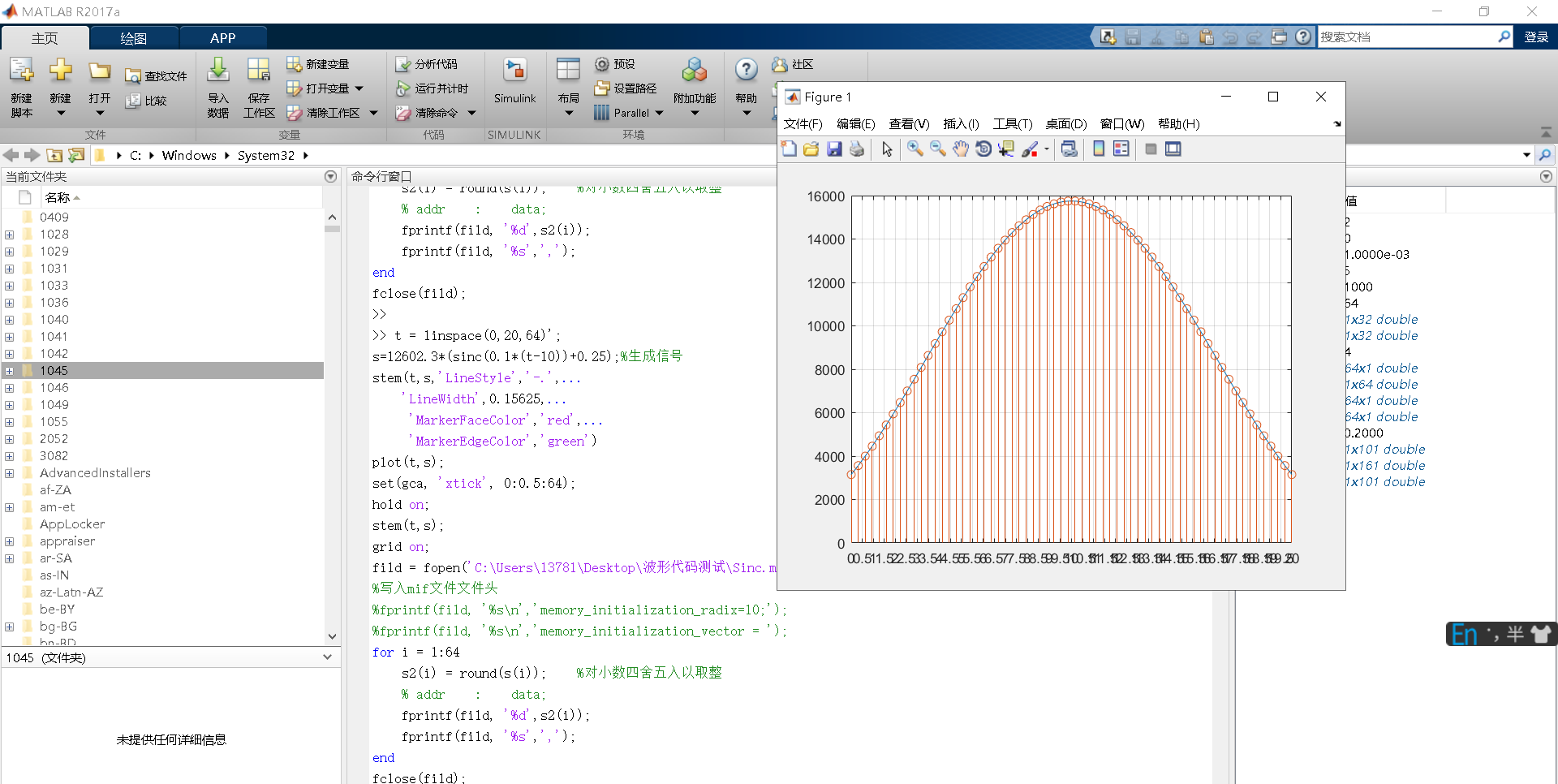

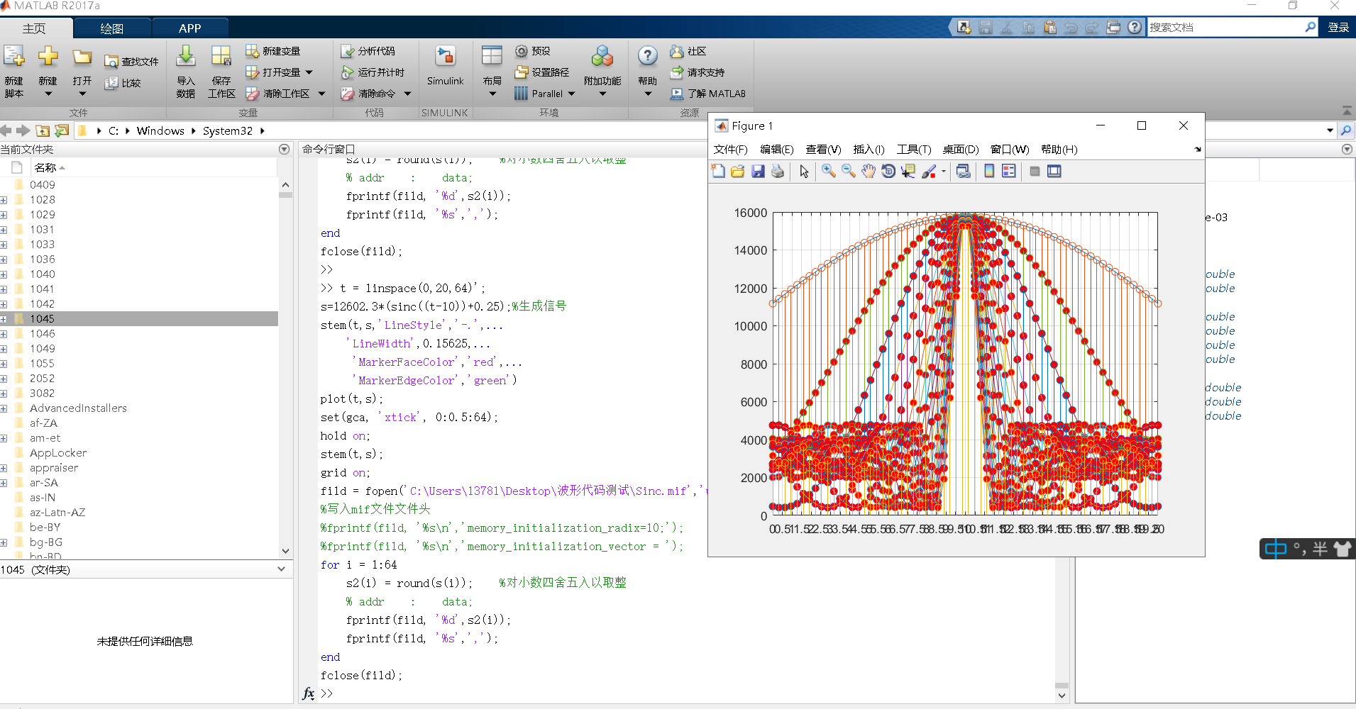
Please see the attachments for Matlab and STM32 code; only a brief explanation is provided here. Please note the red text in the screenshots above: waveform parameters cannot be negative and cannot exceed 16383!
Physical Demonstration:
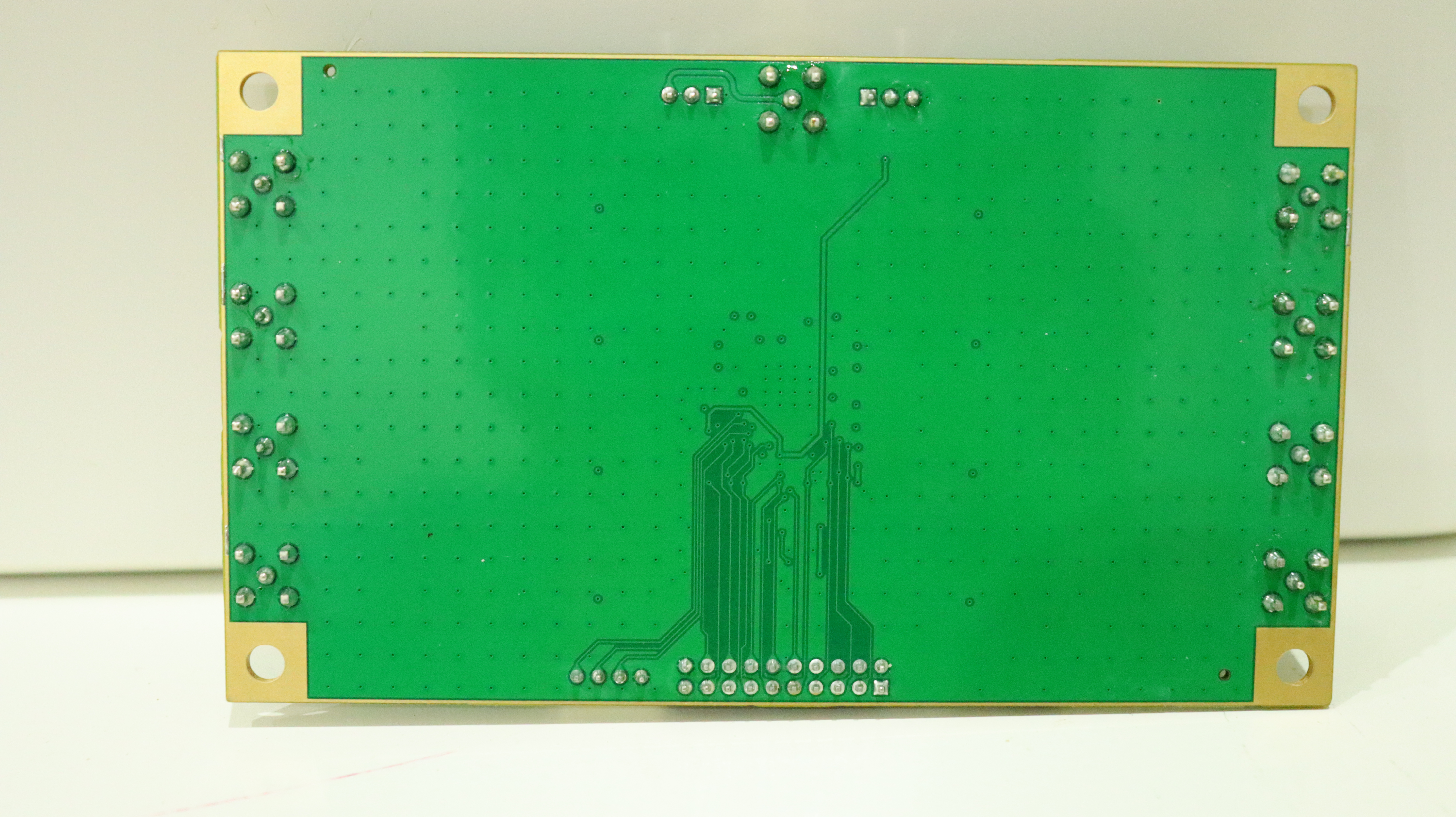
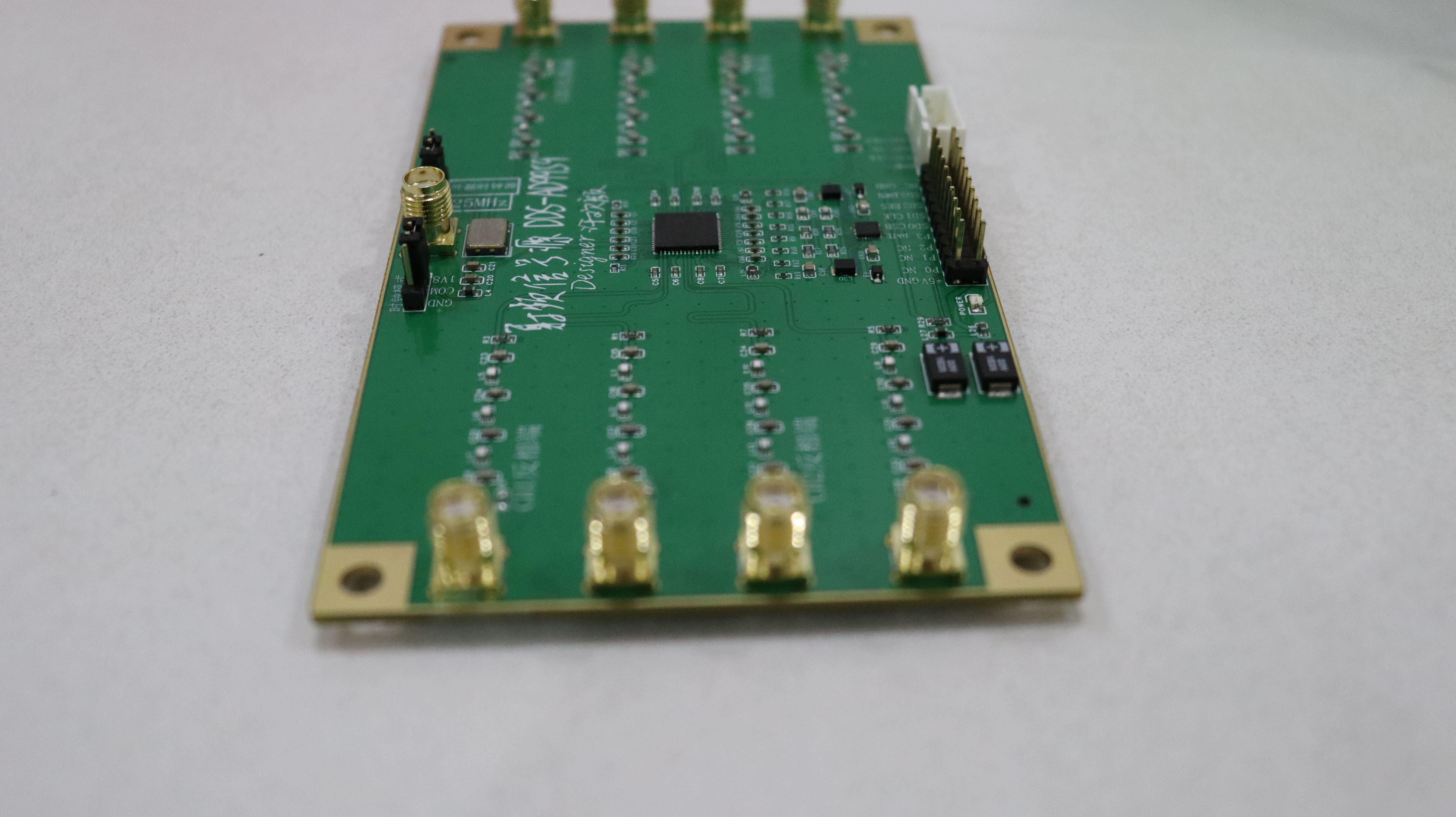
①. Module DDS-AD9959:
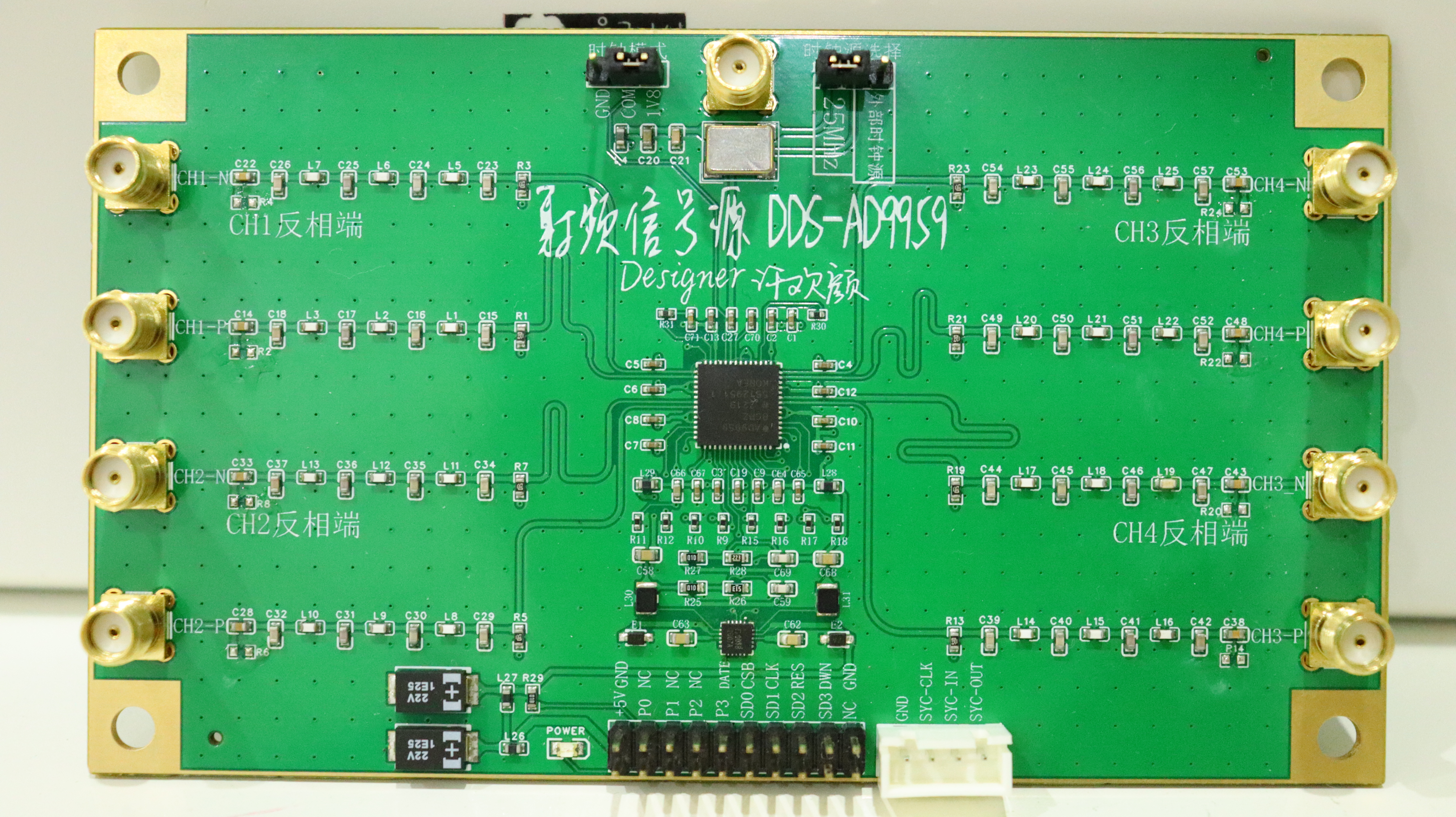
Gold-plated edging!!! Very beautiful.

②. Module DDS-AD9910:
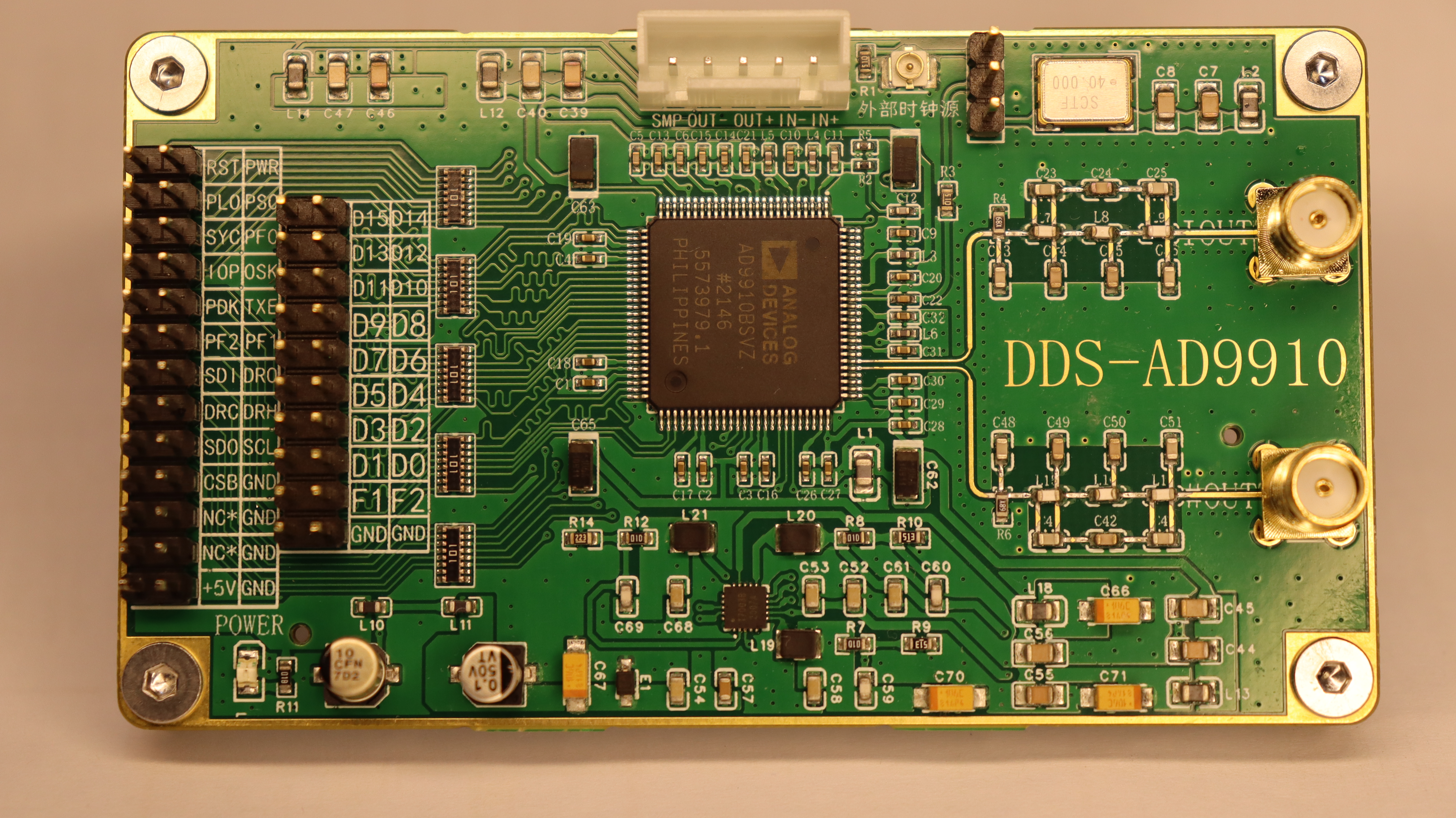

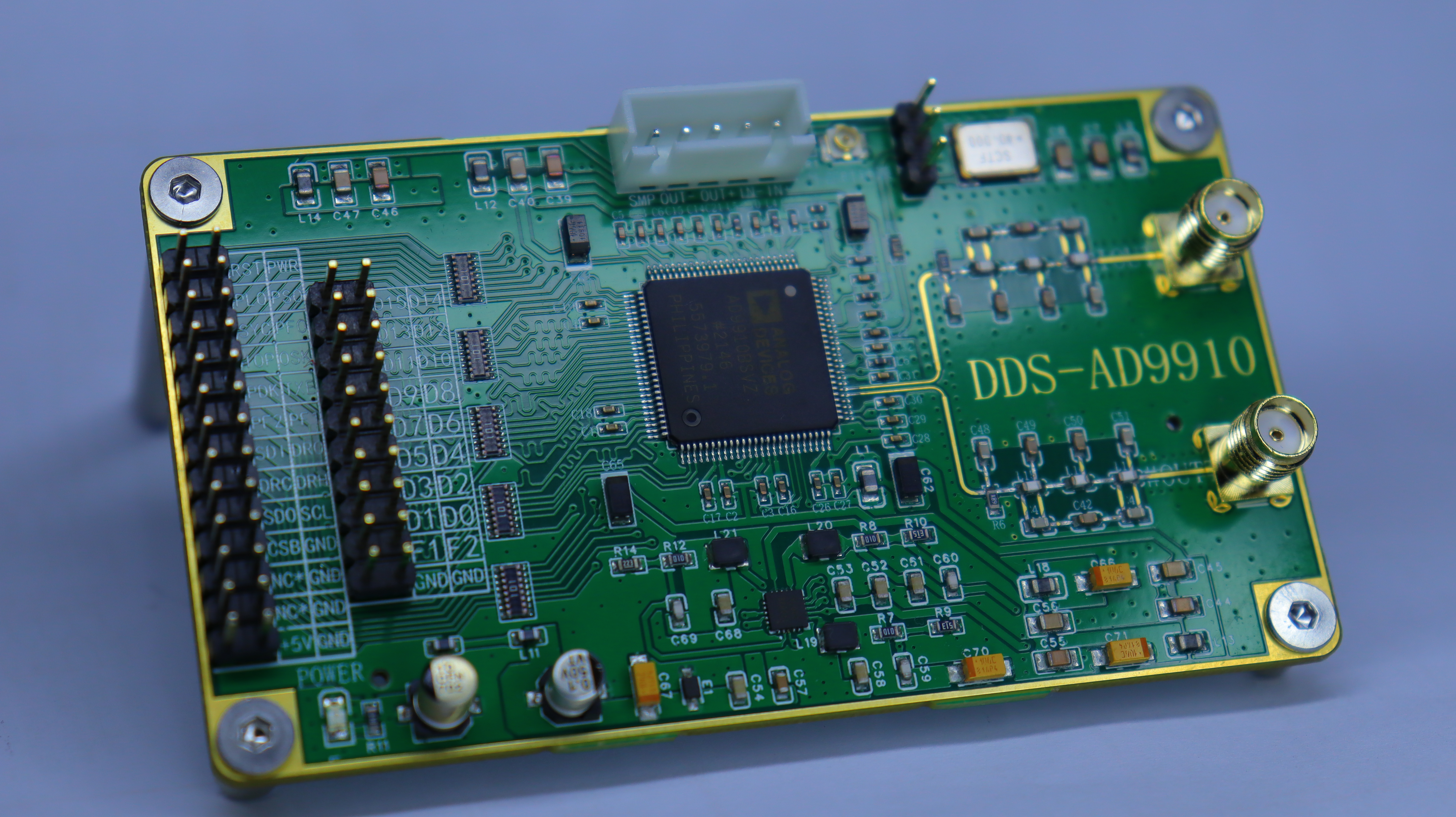

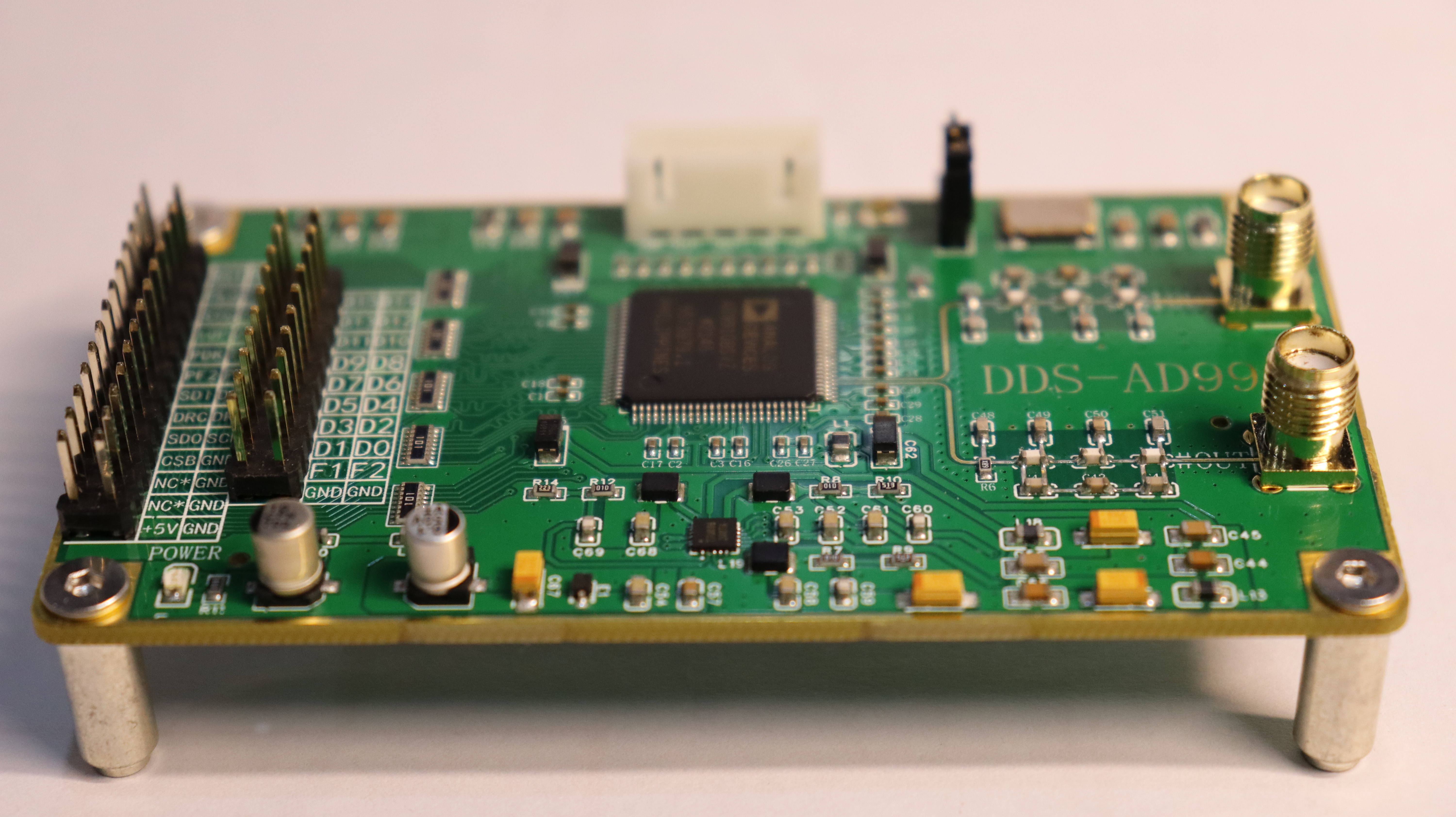
When laying out the AD9910, its layout structure is very user-friendly, requiring only a large fan-out to complete the data line arrangement, which is unmatched by the AD5595.
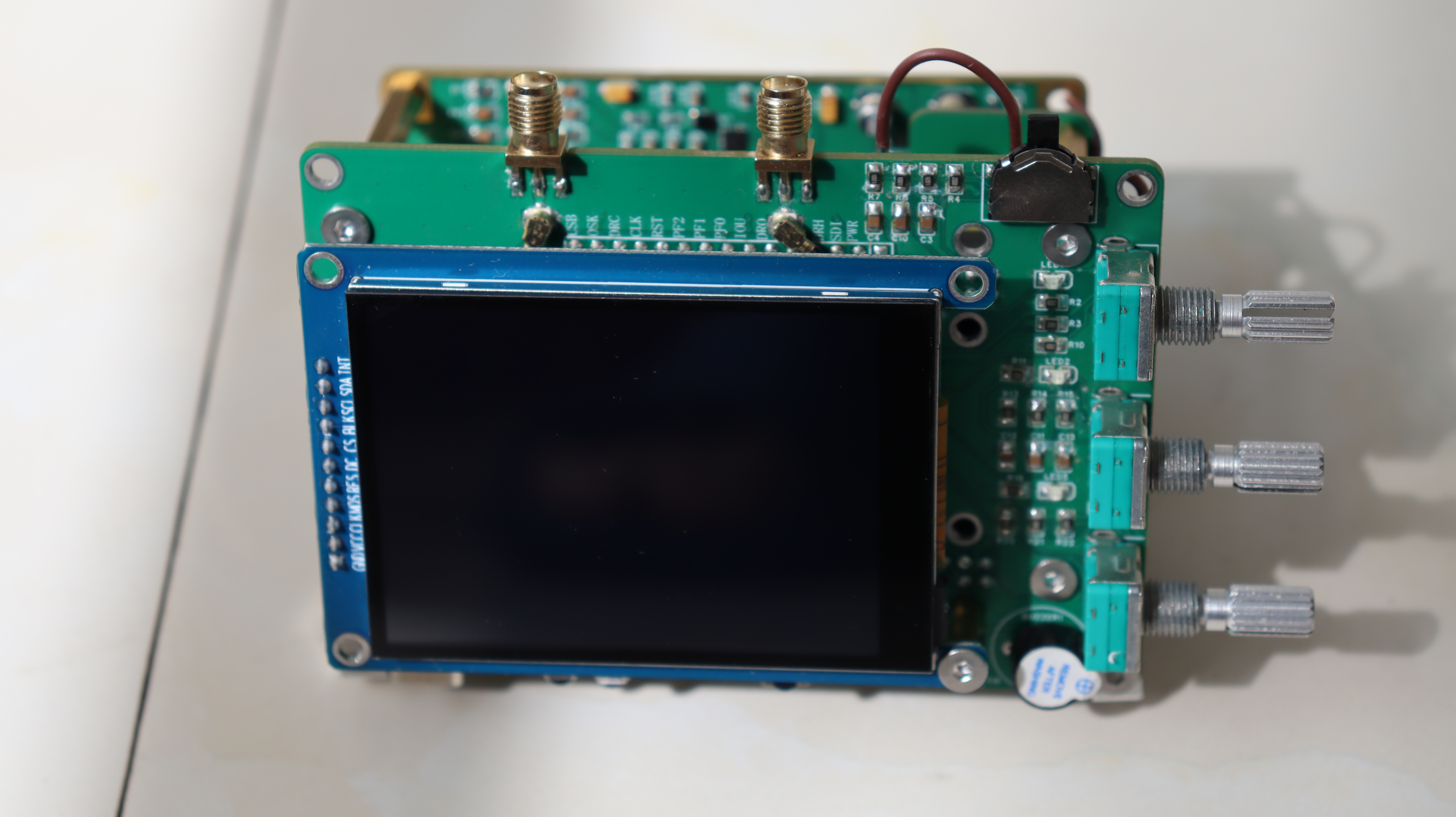
③. Overall System Physical


In addition to high-frequency circuits, the following are generally used: immersion gold process, metal edging, and multi-layer board design. This design uses all of these. In actual development, to reduce costs, double-layer board design is often used. Therefore, the actual project requirements need to be determined based on cost.
It should be noted that DDS chips are generally very expensive, such as AD9910 and AD9959, which are around 200. One way to save costs is to use salvaged chips, which cost only tens of yuan and can greatly reduce costs!
Design Principle
I: AD9959 Schematic Design Description The
AD9959 datasheet is in English, and I did not read the details carefully. High-frequency circuits have high requirements for power supply filtering and isolation, which is very important. The circuit design references some typical schematic diagrams, expanding from 4 outputs to 8 outputs because each output of the AD9959 is extended with an inverted waveform for verification. In the AD9959, the filtering circuit is mainly implemented through ferrite beads. The circuit structure is shown in the figure.
The power supply circuits used on Taobao generally employ AMS1117 series LDO chips. These LDOs tend to overheat during 1.8V power conversion. This design replaces them with TMI1007B. The circuit structure is shown below, and actual verification demonstrates a significant reduction in overheating. However, one of the two PCBA circuits produced by SMT was unusable, most likely due to substandard chip quality. Caution is advised when purchasing from Taobao.
I. AD9910 Schematic Design Instructions:
The AD9910 datasheet has a Chinese version, so the circuit design references the Chinese version. The power supply design follows the above power grouping principles; please refer to the schematic design for details. Further explanation is omitted here; the datasheet is attached.
Software Instructions:
Matlab Code for Generating Arbitrary Waveforms. The following screenshots show arbitrary waveforms generated using Matlab.
Please refer to the attachments for Matlab and STM32 code; only a brief explanation is provided here. Note the red text in the screenshots: waveform parameters cannot be negative and cannot exceed 16383!
Physical Product Demonstration:
①. DDS-AD9959 Module:
Gold-plated edging!!! Very beautiful.
②. DDS-AD9910 Module Demonstration:
When laying out the AD9910, its layout structure is very user-friendly, requiring minimal fan-out for data cable arrangement, something the AD5595 cannot match.
③. Overall System Physical
Design Considerations:
1. For high-frequency signal source modules, the DC-DC circuit should use a multi-channel DC-DC chip; otherwise, the LDO will overheat severely. The circuit used in this design ensures that the LDO will not become hot to the touch after prolonged operation.
2. For LSQP packaged chips, SMT (Surface Mount Technology) is recommended. Hand soldering can cause problems that are difficult to troubleshoot, but SMT can also have issues. For chips that are difficult to solder and are not available on LCSC's online store, it is recommended to find a reputable supplier on Taobao that sells genuine original products. This is because only one of the two SMT boards for AD9959 and AD9910 is usable! This is because the DC-DC chip cannot output a normal 1.8V level, meaning the power conversion chip is faulty.
3. For high-frequency signal boards, a multi-layer board design is recommended, using immersion gold plating and edge banding to achieve the best power coupling effect and reduce external interference.
4. Generating arbitrary waveforms requires a certain understanding of the waveform, such as amplitude and frequency parameters. All operations are implemented through the internal registers of the AD9910, requiring a basic understanding of register operations.
Demo video: https://www.bilibili.com/video/BV1bN411u7sT/


 京公网安备 11010802033920号

 7565LN103Z5


