
Acknowledgements:
This design was inspired by a post on EEVblog: [link].
The schematic prototype is based on a design by Jay_Diddy_B.
Introduction:
Dynamic loads can be used to generate (consume) controlled, rapidly changing currents, creating disturbances in the power supply's control loop. The response to step load changes provides an indication of the power supply's stability margin. Compared to using a loop tester to generate a Bode plot, dynamic loads are much simpler, faster, and less expensive.
The following diagram roughly illustrates the relationship between transient response and output phase margin (source: YouTube)

. All functions have been tested and are working correctly.
Parameters and Usage Instructions:
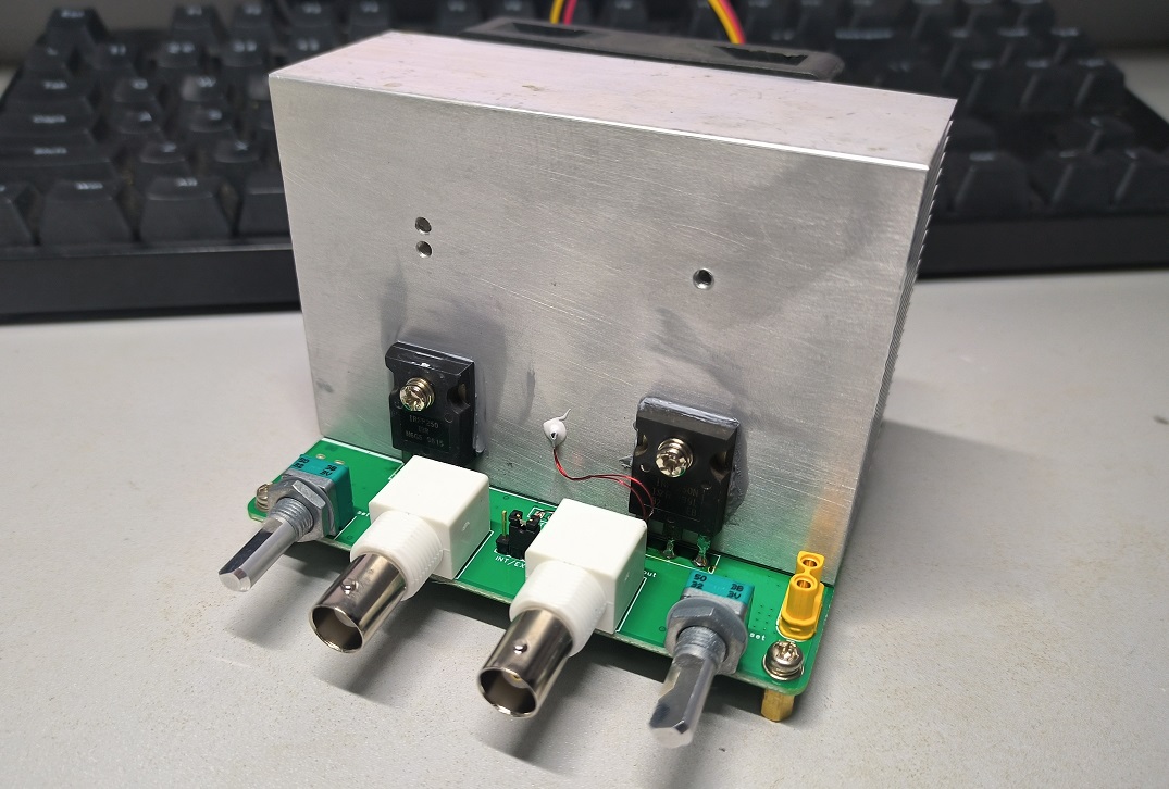
If mica insulation is not used (recommended not to use it for optimal heat dissipation), the heatsink should be connected to the positive terminal of the power supply under test. Be careful to prevent short circuits!
Input voltage range: 36V max (limited by input TVS:D3)
Maximum current: 12A
Maximum power dissipation: 120W
Step current: 6A
When using, first plug in a Type-C power supply to provide operating power (you need to manually measure whether you have successfully obtained 12V voltage). The blue LED is the operating power indicator. Connect the power supply under test (DUT) to the XT30 connector. It is recommended to use short, thick wires, or at least twist the positive and negative wires together to reduce parasitic inductance. The green LED indicates that the DUT is connected. First, adjust the left potentiometer knob to set a constant current, then adjust the right potentiometer knob as needed to set a step current. The pin header and jumper cap in the middle of the BNC connector can be used to set an arbitrary waveform current using the internal current setting or the input voltage of the left BNC connector, with a ratio of 100mV/A. The right BNC connector outputs the actual current detection value, with a ratio of 1V/A. When the heatsink temperature rises to a certain level, the cooling fan will automatically start. When the temperature continues to rise and triggers over-temperature protection, the red LED will light up, the load will stop working, and it will automatically resume working after the temperature drops.
Design Principles:
The following briefly introduces the functions and implementation principles of each block diagram in the schematic diagram .
Power stage: Main power stage. The N-MOS IRF250N operates in the linear region, acting as an adjustable resistor. The voltage flowing through the sampling resistor is amplified 20 times by the INA180A1 and then fed into the error amplifier U1 to control the gate, achieving negative feedback and stabilizing the current. The constant current magnitude can be controlled by controlling the voltage at CUR_SET. The system bandwidth can be set by adjusting C1 and C3.
Total current sense: The incoming current is converted into a voltage with a fixed 2.5V bias by the CC6920 Hall effect current sensor, then amplified 5 times by the differential amplifier composed of U9.2 and the bias voltage is eliminated, outputting 1V/A, which can be read by an oscilloscope or voltmeter.
NTC temp sensor: The 5V voltage is divided by NTC and R27 and then fed into the follower U9.4 to reduce the output impedance to avoid the influence of the input impedance of the subsequent hysteresis comparator.
Auto fan control & OVP: Automatic fan start/stop control and over-temperature protection. Op-amps U8.2 and U8.3 form a hysteresis comparator, controlling the fan's on/off state and, when the temperature is too high, pulling down CUR_SET to shut down the electronic load. The purpose of using a hysteresis comparator is to prevent frequent jumps at the threshold.
Internal current setting: This part of the load generates adjustable constant voltage reference and step voltage reference. TL431 is responsible for generating a stable 2.5V voltage as a reference. U8.4 is a square wave oscillator circuit that controls the on/off state of Q1. After voltage division by potentiometer R24 and follower U8.1, an adjustable square wave is generated as the step voltage reference STEP_CURRENT_SET. The constant voltage reference CONST_CURRENT_SET is obtained by directly dividing the 2.5V reference through potentiometer R26. The constant voltage reference and the step voltage reference are divided by the subtraction unit U9.3 to generate the final reference voltage. Specifically, the constant voltage reference is amplified by two times and then the step voltage reference is subtracted, that is, the step voltage is subtracted from the constant voltage to achieve an arbitrarily set step current (within a certain range).
USB PD Decoy: PD decoy. A CH224K is used to obtain 12V power from various fast charging heads to power the control circuit and fan.
Tested power input: Preprocessing of the power supply under test. The focus of this part is the damping network composed of R45-R48 and C15/C16. Due to the parasitic inductance of the input cable, it is needed to reduce high-frequency gain, increase gain margin, and improve stability.
Assembly instructions:
In addition to the components in the schematic, the following accessories are required:
One 3950K 10KΩ NTC resistor (with wire);
two BNC male-to-male wires (monitor level is sufficient); one aluminum fine-toothed heatsink with input/output bandwidth
, measuring 100mm long, 69mm wide, and 36mm high, with holes drilled and tapped for mounting MOSFETs.
One 12V 7CM fan.
One Type-C fast charging adapter supporting 12V output.
Several M3 screws and copper pillars.
One
tube of thermal paste. One tube of thermal adhesive.
I actually used TP2274 and TP2272 op-amps. Using LM324/LM358 may affect the comparator threshold/loop bandwidth, so please pay attention when preparing the components.
After assembling the components, attach the NTC resistors to the heatsink with thermal adhesive (note that it is not thermal paste) as shown in the diagram, and solder them to the corresponding pads. Apply thermal paste (note that it is not thermal adhesive) between the MOSFET and the heatsink.
The fan can be directly attached to the PCB. Refer to the main diagram for the rest of the assembly.

Test data:
CH1: Voltage across the sampling resistor; CH2: Total current monitoring output voltage (
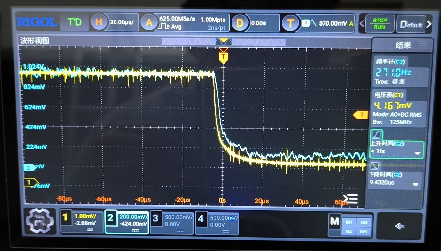
16-point averaging enabled, magnified observation of falling edge, fall time 9.43µs)
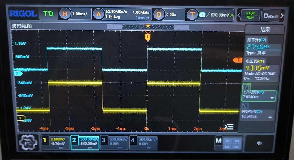
; CH1: Voltage across the sampling resistor; CH2: Total current monitoring output voltage (

16-point averaging enabled, magnified observation of rising edge, rise time 7.03µs)
; CH1: Voltage across the sampling resistor; CH2: Total current monitoring output voltage;

CH1: INA180 output voltage; CH2: Total current monitoring output voltage. It can be observed that the Hall current sensor noise is quite significant.
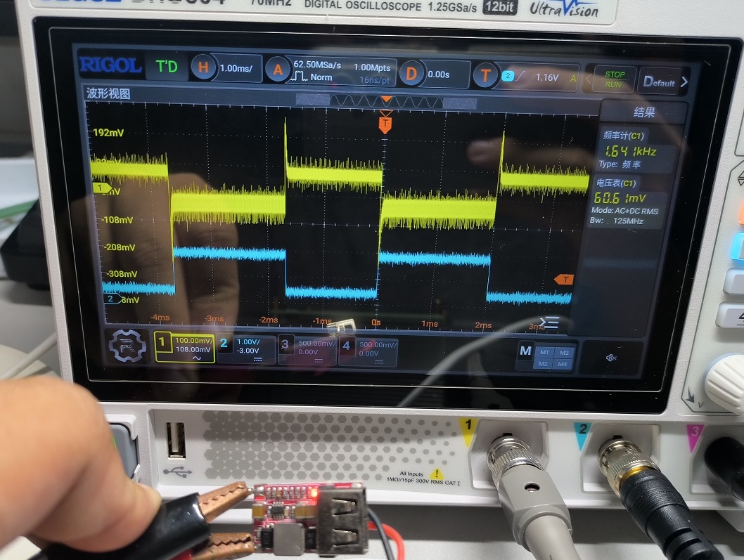
Regarding the transient response of this relatively acceptable step-down module, the voltage quickly recovers to a stable value without ringing. Based on the response time, the loop bandwidth can be approximately calculated.
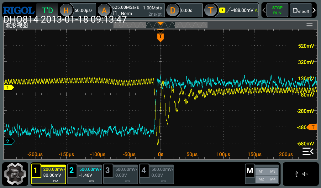
CH1: Output voltage (AC coupled), CH2: Total current monitoring output voltage.

A poor transient response of a buck adjustable power supply exhibits significant output oscillation and a long settling time (unable to stabilize within one test cycle).
CH1: Output voltage (AC coupled), CH2: Total current monitoring output voltage.
Example of use: The transient behavior
of a typical buck circuit is shown in the following figure: CH1: Output voltage (AC coupled), CH2: Total current monitoring output voltage. It can be seen that a significant oscillation occurs at the rising edge of the step current, a typical manifestation of insufficient phase margin. Next, following the datasheet, a feedforward capacitor (10pF) is added . The transient behavior after adding the capacitor is shown in the following figure:


CH1: Output voltage (AC coupled), CH2: Total current monitoring. The output voltage
oscillation has been significantly improved, but the phase margin is still insufficient, and the feedforward capacitor needs to be further increased (mainly because there is no suitable pF-level capacitor on hand, only a 10pF capacitor).


 京公网安备 11010802033920号

 1N6268A/4-E3


