
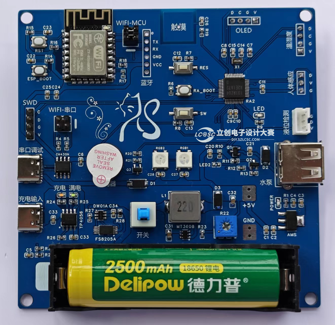
 Circuit Board Image
  , Temperature and Humidity Sensor, OLED Module,
 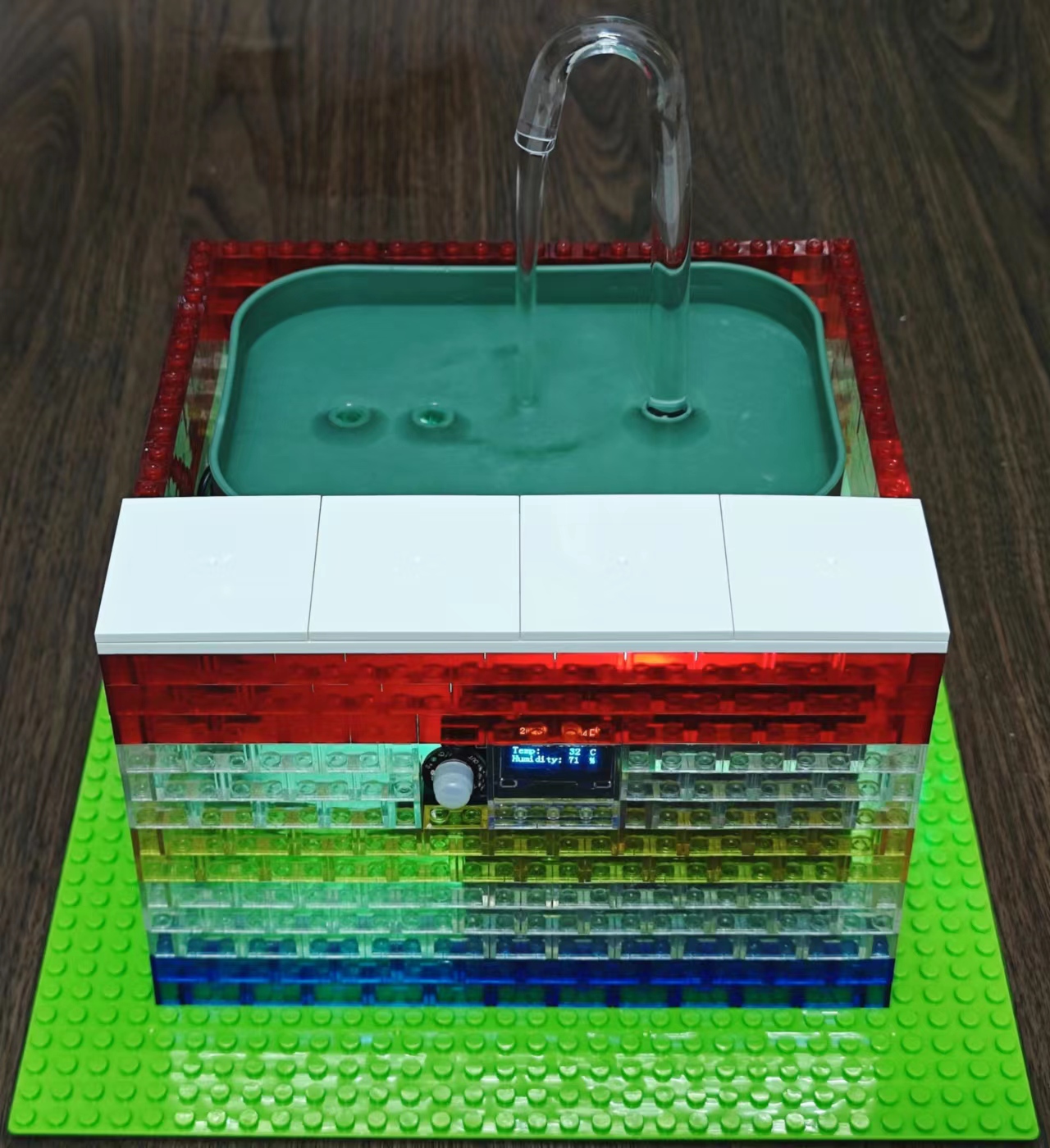 Smart Water Dispenser Front,
  Smart Water Dispenser Side (Charging Interface),
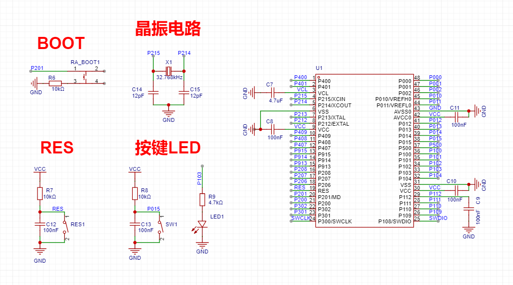
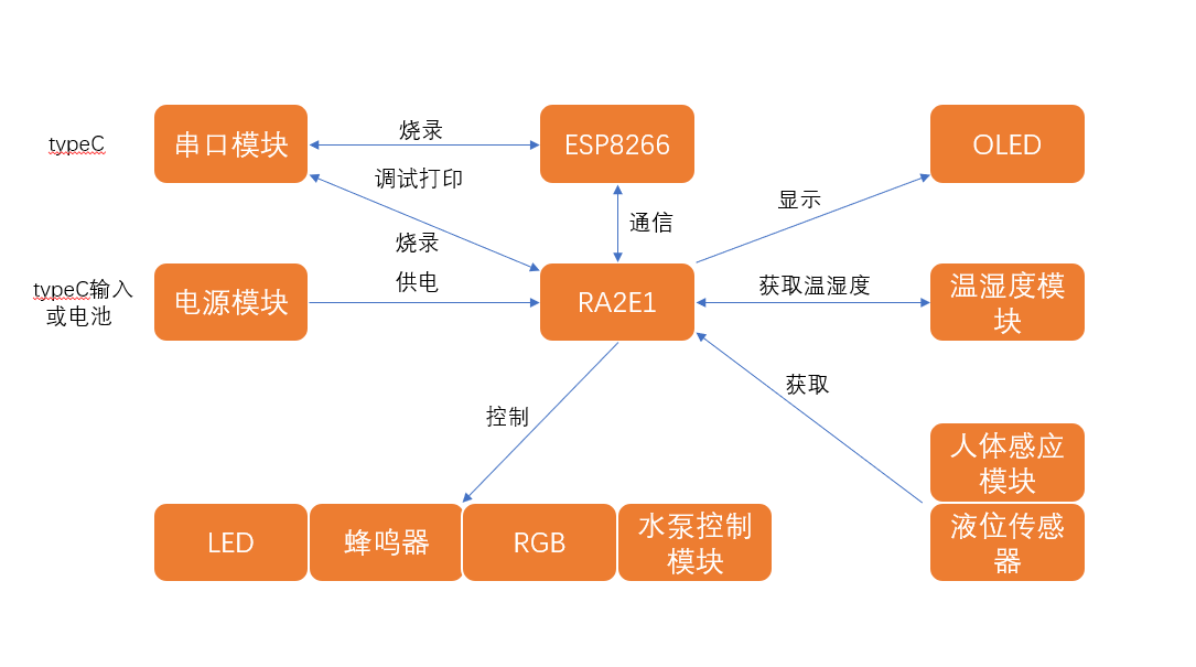
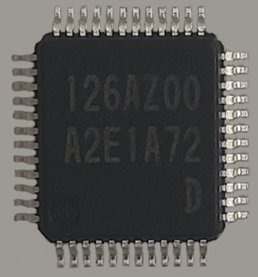 : R7FA2E1A72DFL Chip Features:
 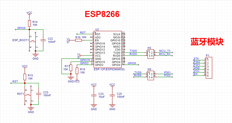 When purchasing the ESP8266, it's best to buy one with AT firmware. If not, you'll need to download it yourself.
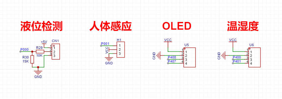 Liquid level sensor and
 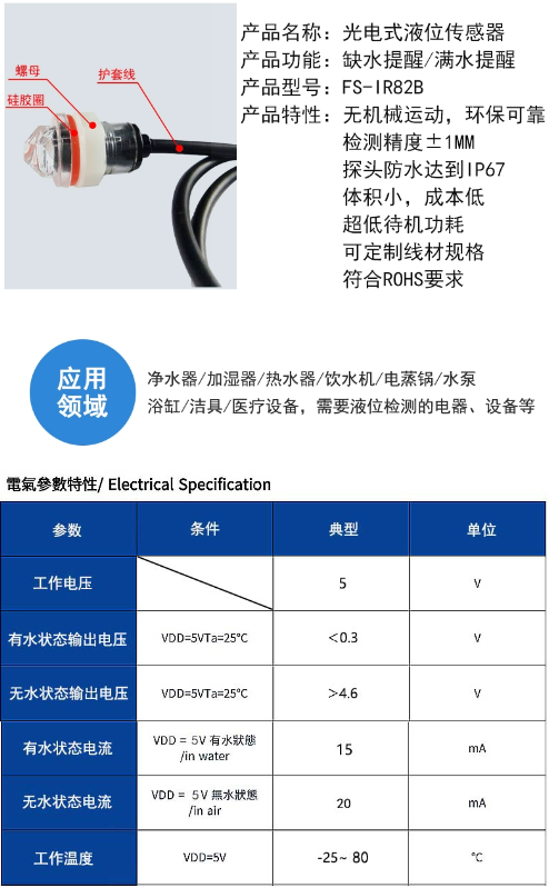 human body sensor
  have fast response speed, low static power consumption, high sensitivity, small size, and are easy to install. The lens and pin headers are already installed and soldered. With a power supply, no debugging is required. Features: 1. The high-level output time is adjustable from 2.5 seconds to 1 hour. The factory-set output time is 2.5 seconds. If needed, a surface-mount resistor can be changed. 2. Lockout time: 2 seconds, not adjustable. 3. Factory-defined as retrievable and cannot be changed. 4. The module's supply voltage is 3.3V to 15V, and the maximum voltage is 2.8V to 18V. 5. The module's output timing is: after power-on, it outputs a high level for 2 seconds, then changes to a low level to enter standby mode. If the delay time is changed, the time for the module to output a high level after power-on will increase accordingly. This can be understood as the startup time to enter normal working state after power-on will increase. 6. After installing the photosensitive element, it will not work during the day but will work at night. Without the photosensitive element, it will work all day (the default is that no photosensitive element is installed). 7. This module is very sensitive. Pay attention to the installation location and try to avoid heat sources and radiation sources (air outlet/sun). 8. The sensitivity of this module is adjustable. A surface-mount resistor
 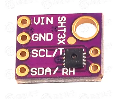 1. Humidity measurement range: 0~100%RH
 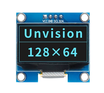 1. High resolution: 128*64 2. Ultra-wide viewing angle: greater than 160° 3. Ultra-low power consumption: 0.06W during normal display 4. Wide power supply range: DC 3.3V-5V 5. Industrial grade: operating temperature range -30°C~70°C 6. Small size: 27mm*27mm*2mm 7. Communication method: IIC 8. Brightness and contrast can be controlled by program commands 9. Service life of no less than 16,000 hours 10. Internal driver chip for OLED screen: SSD1306
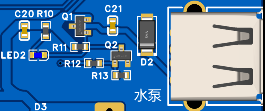
 : When P111 outputs a high level, the water pump turns on (LED2 lights up):
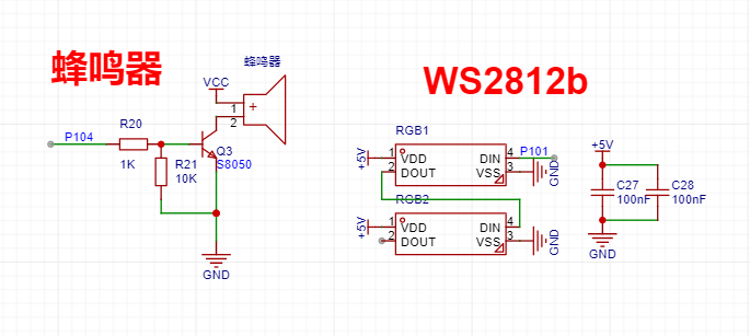 : When P104 outputs a high level, the buzzer sounds:
 is directly connected to the RA MCU by default. Connecting a jumper can be used for programming and debugging ESP8266
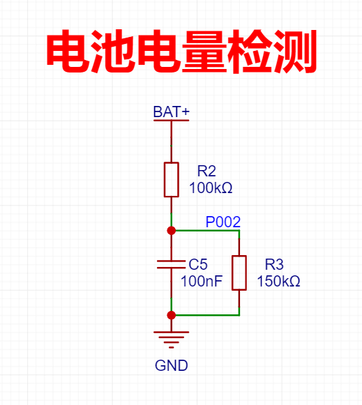 The upper and lower voltage limits of the 18650 lithium battery are 4.2V and 2.75V, respectively.
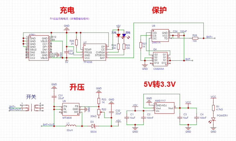 (It is best to solder the power module and debug the 5V output before soldering other modules)
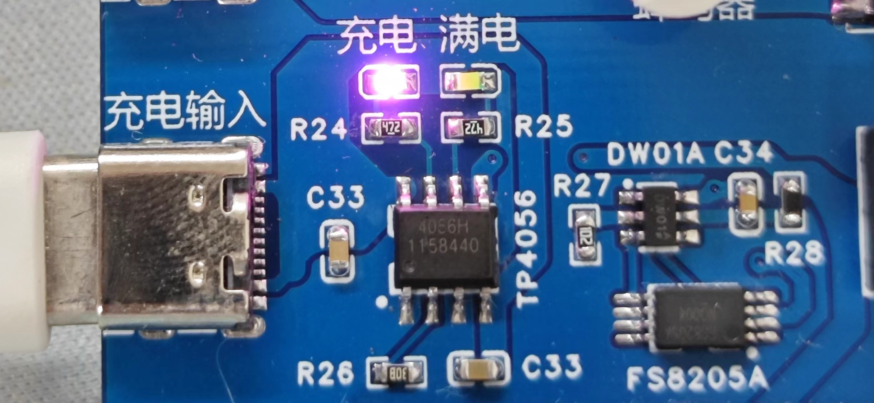


All reference designs on this site are sourced from major semiconductor manufacturers or collected online for learning and research. The copyright belongs to the semiconductor manufacturer or the original author. If you believe that the reference design of this site infringes upon your relevant rights and interests, please send us a rights notice. As a neutral platform service provider, we will take measures to delete the relevant content in accordance with relevant laws after receiving the relevant notice from the rights holder. Please send relevant notifications to email: bbs_service@eeworld.com.cn.
It is your responsibility to test the circuit yourself and determine its suitability for you. EEWorld will not be liable for direct, indirect, special, incidental, consequential or punitive damages arising from any cause or anything connected to any reference design used.
Supported by EEWorld Datasheet
EEWorld
subscription
account

EEWorld
service
account

Automotive
development
community

Robot
development
community

About Us Customer Service Contact Information Datasheet Sitemap LatestNews


Room 1530, 15th Floor, Building B,
No.18 Zhongguancun Street,
Haidian District,
Beijing, Postal Code: 100190
China
Telephone: 008610 8235 0740
 京公网安备 11010802033920号

 BCP52-16


