Project Origin:
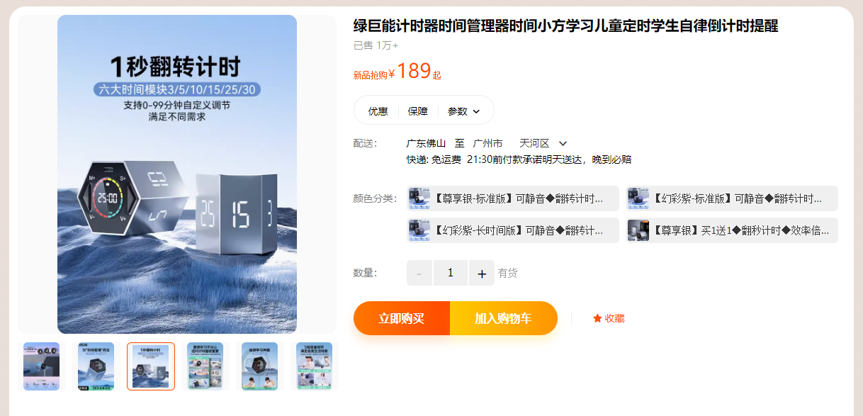
This project originated from an episode of a popular unboxing video on YouTube by the well-known YouTuber UnboxThreapy. He unboxed a timing die, a hexagonal prism with each face marked with a different number. When the user flipped the die onto the corresponding numbered face, it started timing and emitted an audible alert when the time was up. Its working principle is quite simple; it mainly sells on its innovative concept. However, it undeniably simplifies everyday timing needs and is a pretty good product, which inspired me to recreate it. Before officially launching the project, I unexpectedly found this product on Taobao, and it turned out to be from a Chinese company (though I'm unsure if it was copied from overseas).
Description:
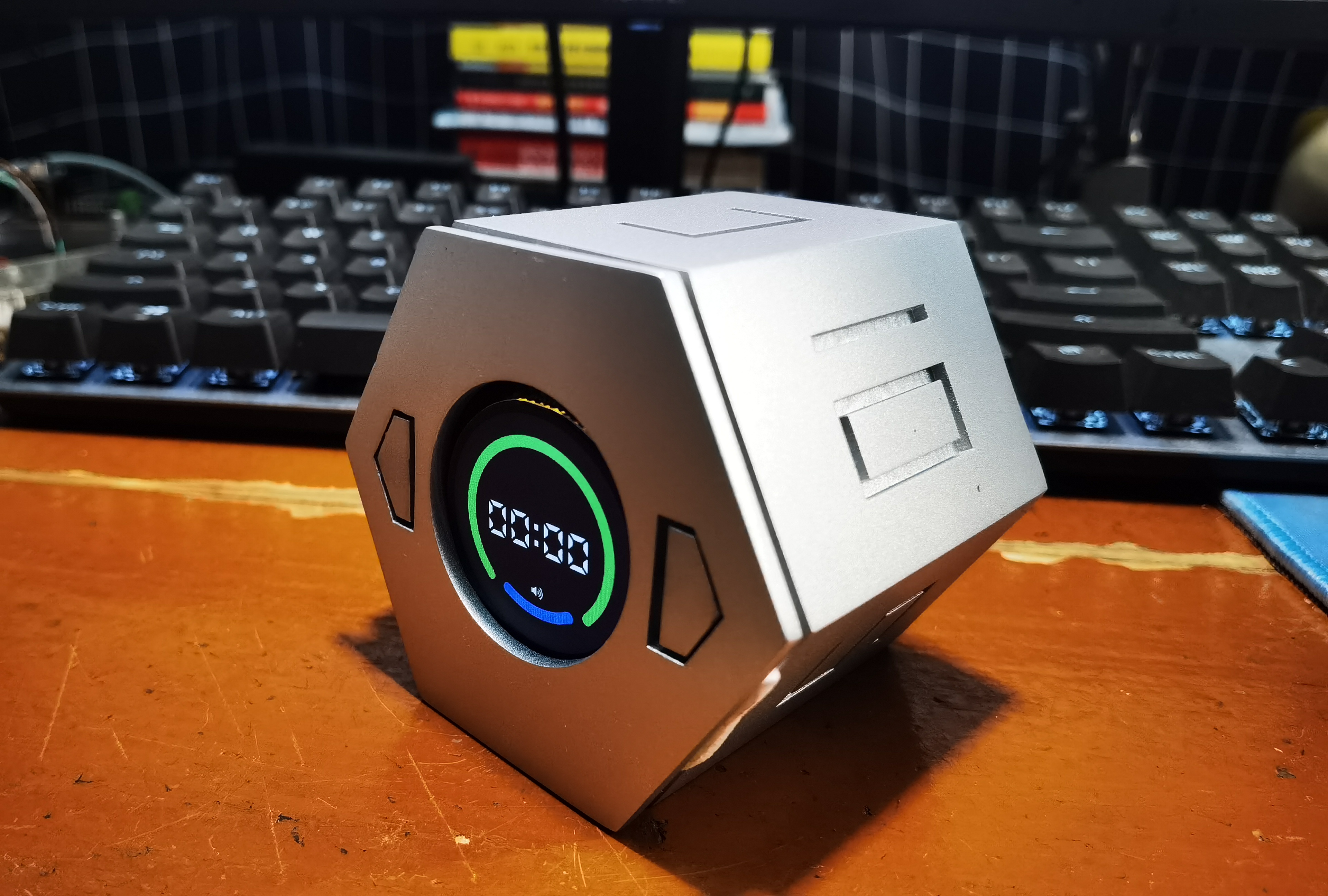
As mentioned earlier, this product replicates a timing die on the market. It's hexagonal prism-shaped with numbers on each face representing the time. When the user flips the die onto the corresponding face, it starts timing and emits an audible alert when the time is up.
In addition, to meet different needs, one of the six sides can be customized by the user, which can be set by the user through two buttons on the front (top) of the hexagonal prism. The front screen will display the basic information of the system, and there will also be a corresponding animation to show the timing progress.
Project progress
2023.05 | Project establishment
2023.08 | PCB board verification completed
2023.08 | Shell design completed
2023.10 | Integration test completed
Design principle
(I) Principle analysis
First, from the function of this product, we can see that the hardware is relatively simple. An external circular screen is used for information display, and two buttons are used for user interaction. Internally, there needs to be an attitude sensor, which is the key to its flip-to-time timing. By identifying the angle of product flipping, the timing time can be determined; there is also a buzzer for prompting. Of course, this product needs to be powered by a lithium battery, so the internal charging and discharging management circuit and power monitoring circuit are also required.
(II) Scheme design
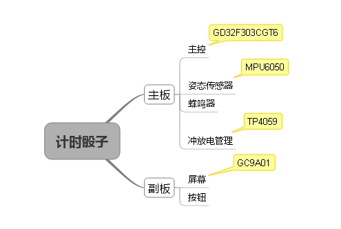
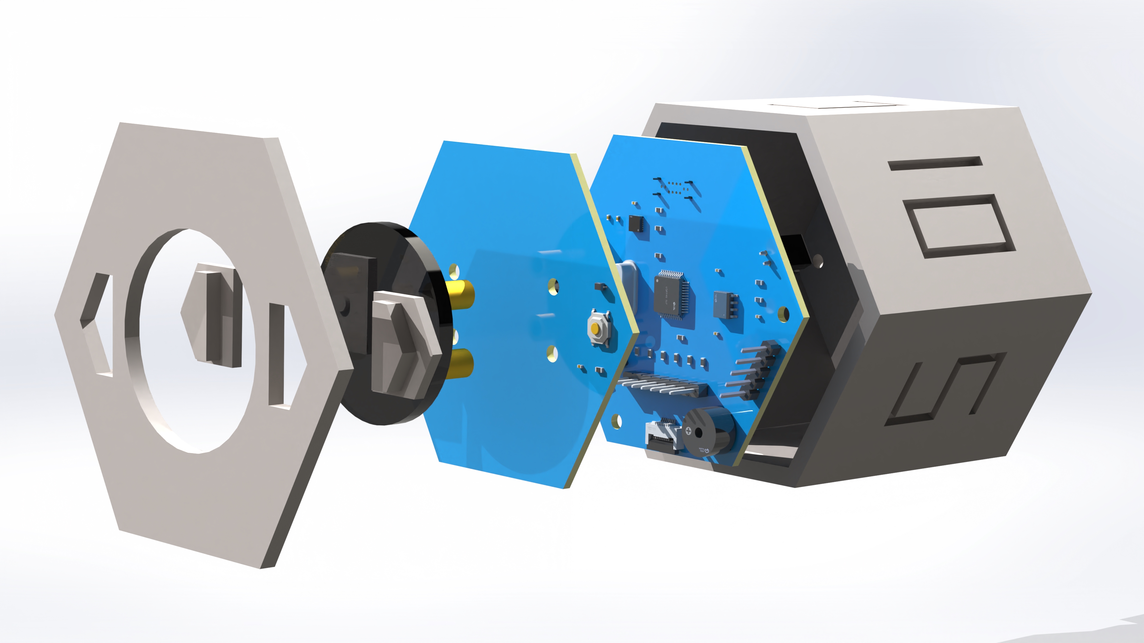
When conceiving the product, it was found that this product would require at least two boards to realize. My design is that the main board is located at the bottom and the secondary board is located at the top.
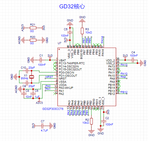
Regarding the choice of main controller, this product doesn't require many external devices, thus minimizing the number of pins. However, for the GUI, I chose the LVGL library, and for the MPU6050, I plan to port the official DMP library. These two libraries consume a significant amount of memory and CPU power, so a Cortex-M4 architecture and a model with ample memory are necessary. Ultimately, I chose the GD32F303CGT6. This model from GigaDevice has a 168MHz clock speed and 1024KB of RAM, fully meeting the needs of this project, and importantly, it's inexpensive.
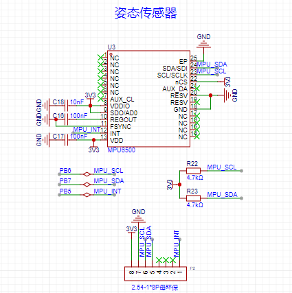
Initially, I considered using a domestically produced chip for the attitude sensor, but considering the current state of the domestic ecosystem and the need to write attitude fusion code myself, I didn't consider it. In contrast, the MPU6050 has plenty of example code available for reference, and the official website also provides a complete DMP library for attitude fusion processing.
Because this product is powered by a lithium battery, charge and discharge management is required. The classic TP4059 chip was chosen, capable of achieving a maximum charging current of 800mA. If speed isn't sufficient, the TP4056 can be used, achieving a maximum charging current of 1A.
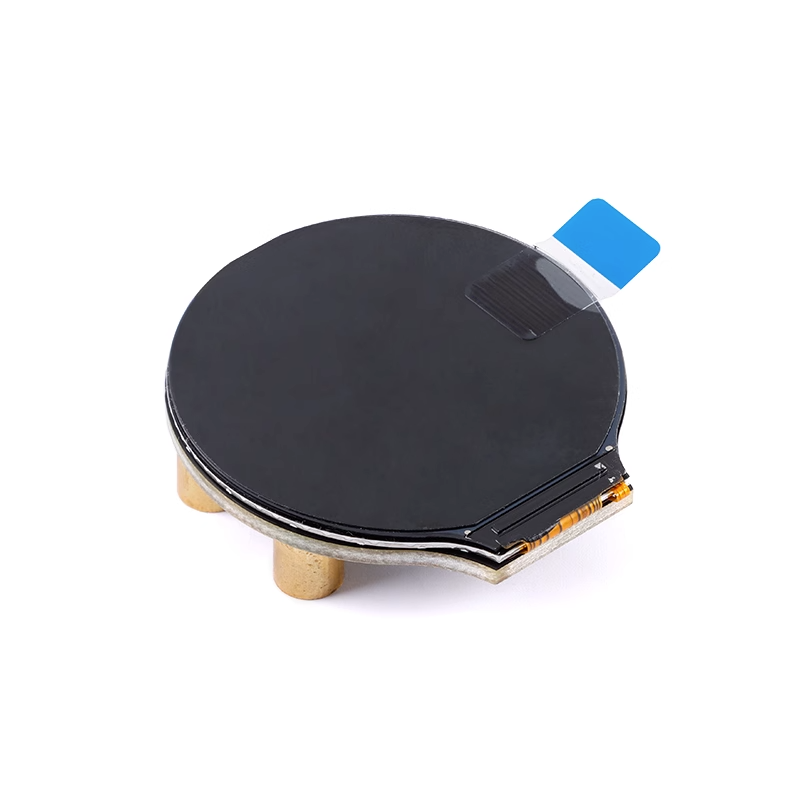
For the screen, a round LCD screen was chosen, with a GC9A01 driver chip, using SPI for communication, and a resolution of 240x240.
Screen purchase link: https://item.taobao.com/item.htm?spm=a21n57.1.0.0.5f5f523cr8s2nu&id=684295016053&ns=1&abbucket=3#detail
(III) Hardware Design
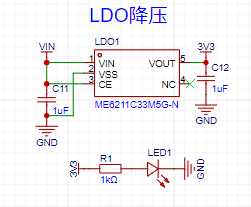
1. Power Supply:
Since it's powered by a lithium battery, an LDO must be used for voltage reduction. The chosen chip is Nanjing Weimeng's ME611C33M5G-N, with a maximum output current of 500mA.
Lithium battery charging and discharging management is crucial. My idea is that during normal operation, the lithium battery provides independent power. When the user plugs in a USB port, the lithium battery's power supply to the board is disconnected, and the USB port simultaneously charges the lithium battery and powers the board. Therefore, I designed the following power switching circuit.
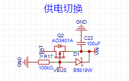
The MOSFET in the diagram is a PMOS. When the USB interface (VBUS) is not connected, the battery current (VBAT) can flow smoothly to VIN. When the USB interface is connected, the MOSFET is turned off, and only the USB interface current flows to VIN. A diode is placed between VBUS and VIN to prevent VBAT from sinking current to VBUS. The voltage drop of the B5819W diode can typically reach over 550mA, which is quite large for such a low-voltage circuit. If you mind this, you can replace it with an SS14, which has a voltage drop of only about 500mA. The parameters are the same except for the voltage drop, but the size will be larger.
The lithium battery charging circuit can generally be drawn according to the datasheet. A 1.5kΩ feedback resistor (PROG) will provide a maximum charging current of 800mA.
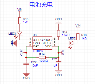
Battery power monitoring can be simply achieved using a series voltage divider, reducing the battery voltage by half. As long as the full-charge voltage is less than the microcontroller's 3.3V, it's sufficient.

2. Main Control Section
The main control circuit can generally be designed according to the datasheet, but an external crystal oscillator is essential because this product is a timer; using an external crystal oscillator ensures accurate timing. Additionally, the ADC power supply and ground are isolated using a 0Ω resistor, which improves anti-interference capability.
3. Attitude Sensor:
The attitude sensor used in the schematic is the MPU6500, which is essentially the same as the MPU6050 except for its lower price. A female header for the MPU6050 is provided. This design is because both the MPU6500 and MPU6050 are QFN packages, extremely difficult to solder by hand. Therefore, if hand soldering is not possible, a ready-made module can be directly connected nearby.
4. Screen:
The screen is fixed to the sub-board, so the main board has an FPC interface for connection. It was discovered early on that if hardware SPI communication with the screen is required, pull-up resistors must be added, which is quite inconvenient. Similarly, a female header is provided for screen connection, as FPC sockets are also difficult to solder by hand.

5. User Buttons:
The user buttons are also on the sub-board and connected to the main board via an FPC. All-metal waterproof buttons were chosen for durability, and a bidirectional transient suppression diode was added to the circuit for protection.
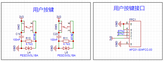
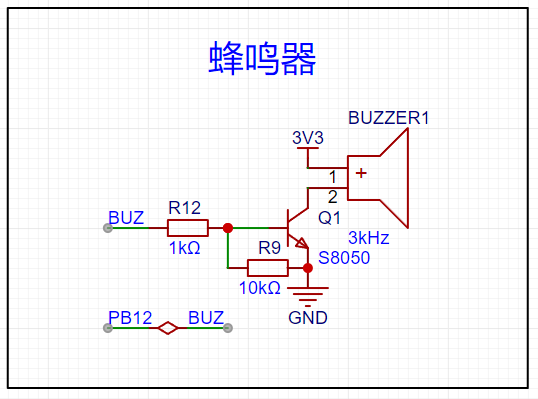
6. Buzzer
: I chose an active buzzer, since every component less soldered is a valuable asset. I simply used a transistor to control the switch.
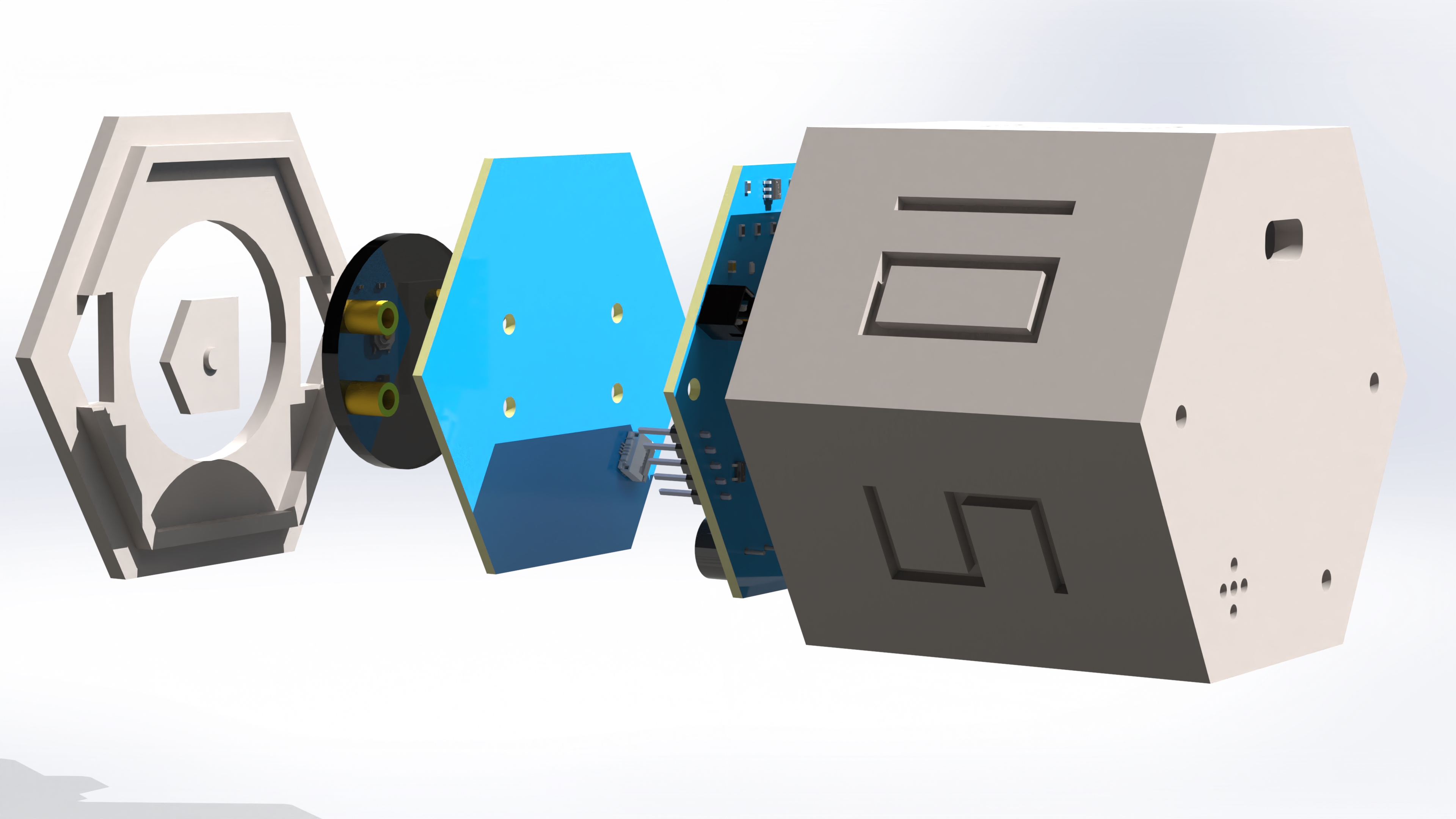
Appearance Design:
The appearance design is rather rough, as this was my first time designing a casing and I didn't have much product design experience.
The original design used aluminum alloy + diffuser plate + plastic, which was obviously a bit pricey. So, I devised a pure 3D printing solution based on my own ideas.
Manufacturing Process
(Part 1): PCB
: Bare PCB board.
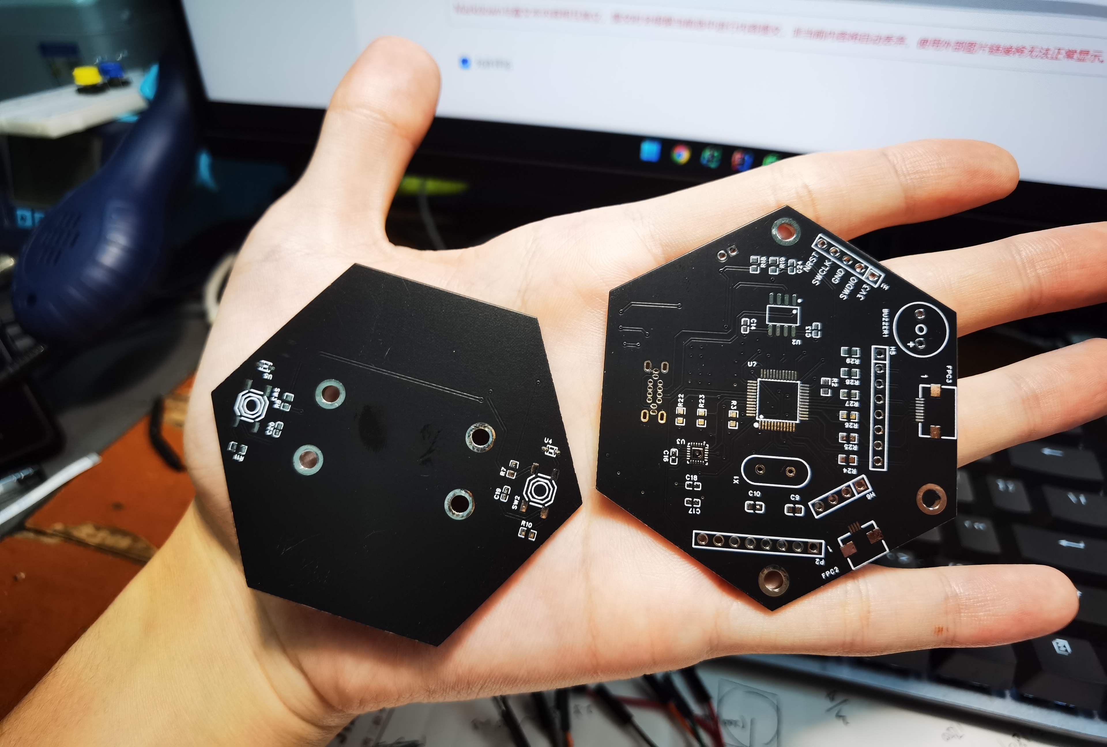
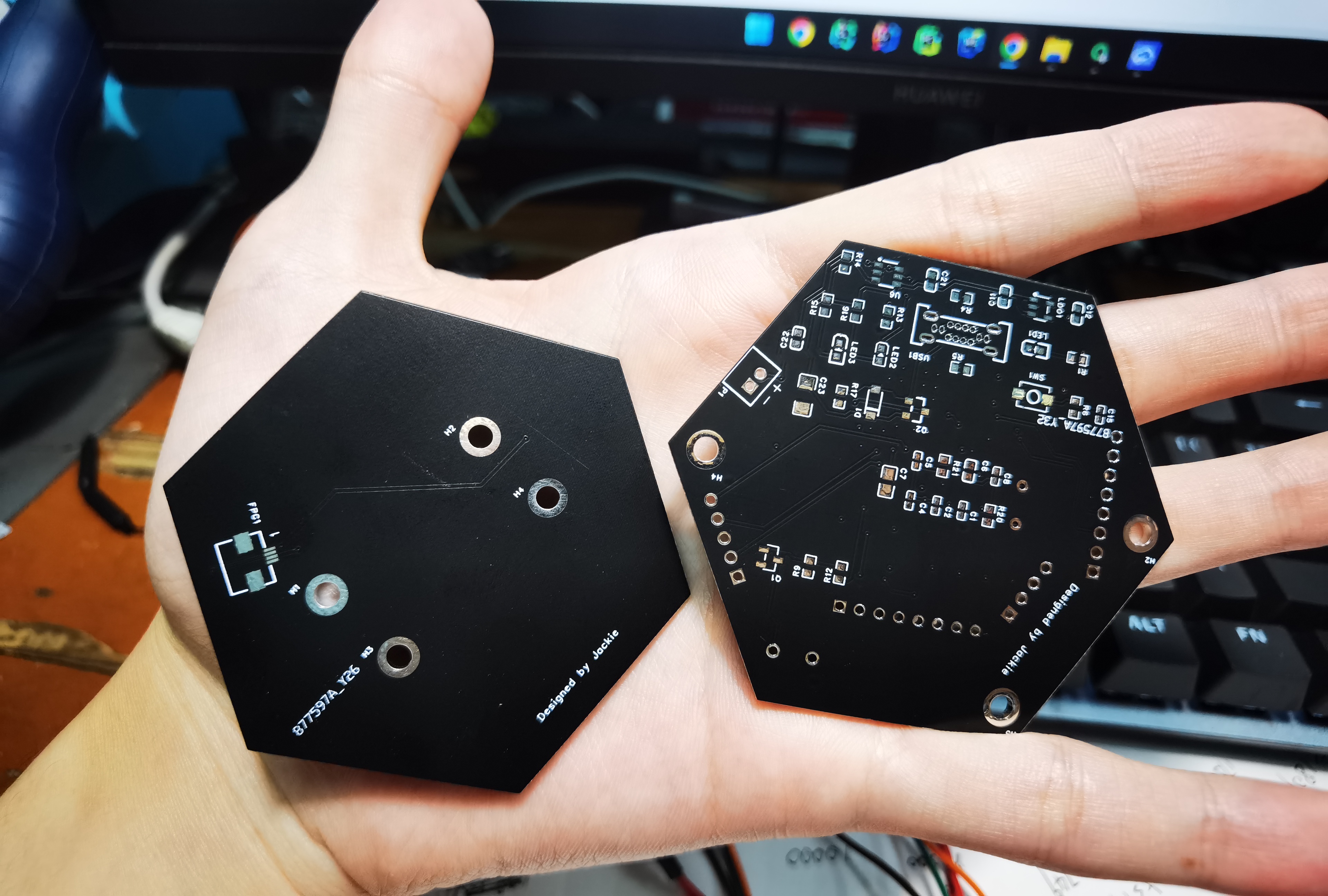
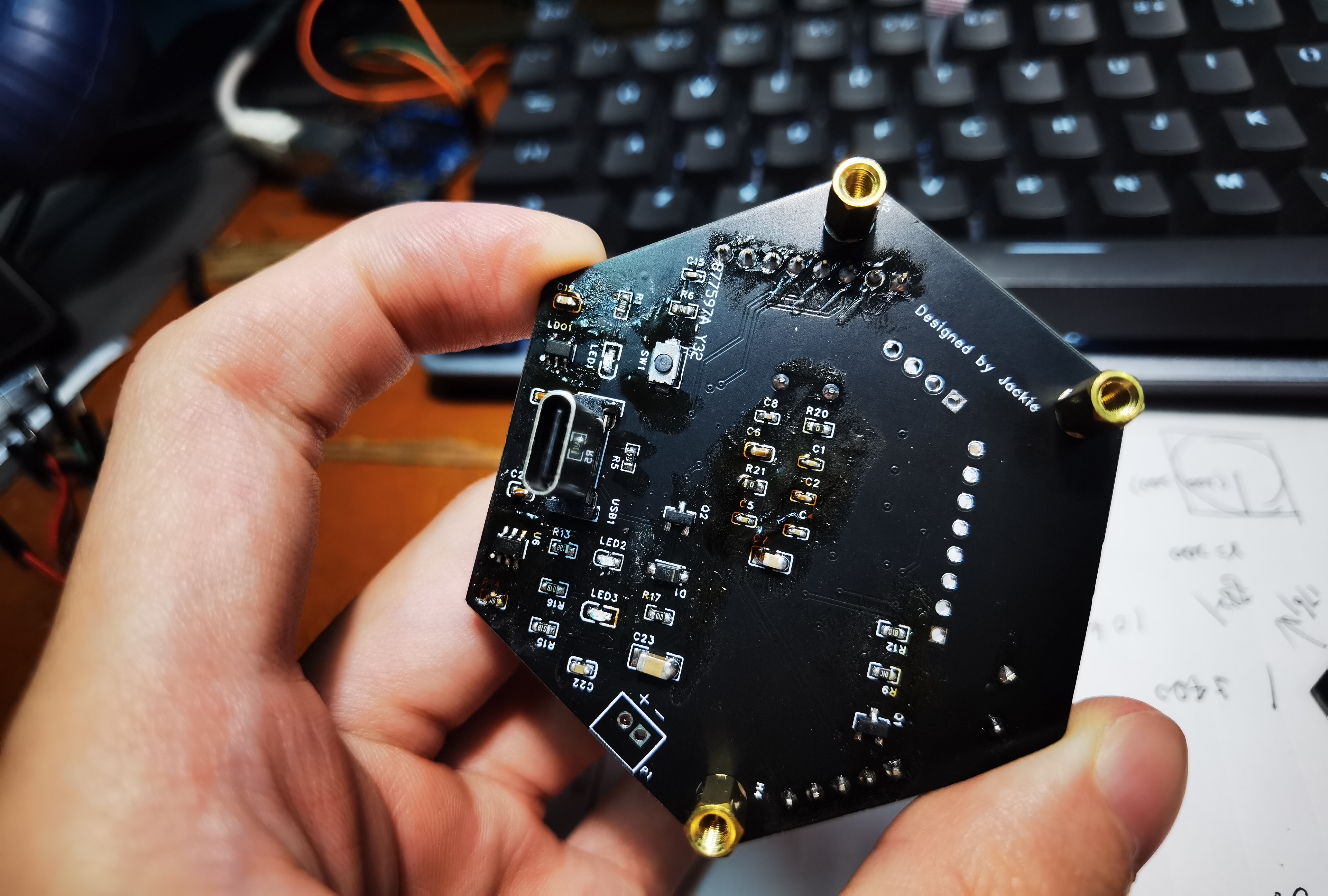
Soldered PCB board.

Simple LVGL port for verification.
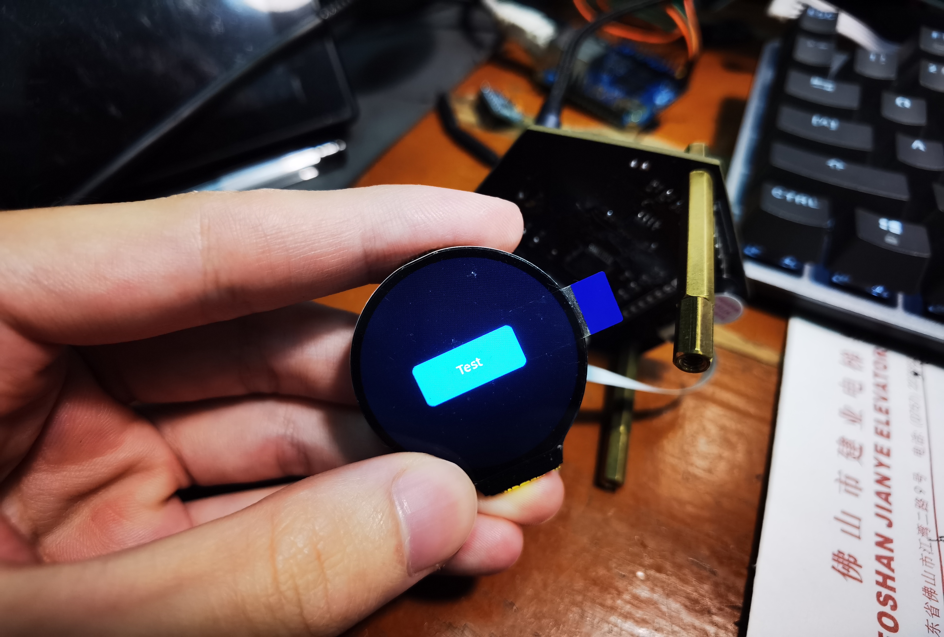
Actual product after assembly.
Summary
This Spark Program project was the most challenging project I've ever undertaken. I had to handle everything myself, from PCB design and casing design to component soldering and coding. For a complete novice like me who had never designed a product before, this was a huge challenge, and obviously, the final product wasn't perfect.
However, I learned a lot from this experience, and I hope to do even better in the next Spark Program. The firmware and 3D casing files for
the attached
project are open source and can be downloaded below.


 京公网安备 11010802033920号

 SN75454BPSRE4


