With the rapid development of science and technology, China's electromagnetic railgun technology has long surpassed that of many developed countries, taking the lead in the world. Now, sharing in the benefits of the country's rapid development, we can easily build our own electromagnetic railguns at home at low cost.
**Disclaimer:
** A sound legal environment requires everyone's joint efforts to maintain; please remember and strictly abide by relevant national laws!
This project strictly adheres to national standards.
It was independently developed and is open-source by the author. Please do not reproduce it without attribution, and please do not use it for commercial purposes without the author's permission (although it seems unlikely anyone would need it, but what if?). You can contact the author via WeChat: WZ1476001 (apologies for not being able to reply promptly due to the upcoming high school graduation season and only being able to go home once a month).
This circuit contains high voltage; please understand the circuit before using it carefully (do not attempt to build it without relevant electronics knowledge, as there are significant safety hazards).
Do not touch the two high-voltage contacts. It is recommended to use insulating heat-shrink film for side insulation and insulating silicone for the first and last high-voltage circuits. The author and platform are not responsible for any safety issues that arise.
Special thanks to:
Dad: Thank you Dad for generously sponsoring the 4 IGBTs!
JLCPCB: Thank you JLCPCB for providing convenient and practical development tools and a good open-source environment for domestic developers, as well as the twice-monthly free PCB prototyping.
Key component materials:
Capacitors: Two 450V 820uF aluminum electrolytic capacitors, 25mm*60mm in size
. Coil: 0.8mm wire diameter, 150 turns, overall height 28mm, outer diameter 20mm, inner diameter 8mm.
Electronic switch: Uses a high peak current automotive-grade IGBT, model AIKQ120N60CT (silkscreen: AK120DCT), peak current 480A. Please refer to the datasheet for specific parameters (AIKQ120N60CT_PDF_Datasheet_Specification Book - Semiconductor Chip (semiee.com)).

Please note that if you did not purchase a genuine IGBT from a professional platform, please do not apply excessive voltage, otherwise it will burn out. Thank you again to my father for sponsoring the four IGBTs!
Protection Diode: High-current fast recovery surface-mount diode RS5M, operating current 5A, corresponding to the through-hole model FR507. Surface-mount packaging is chosen for ease of soldering and a more elegant appearance.
Discharge Resistors: R8~R13 are six 2W power boost resistors in 2512 packages. When purchasing resistors, please be careful not to buy ordinary resistors with a success rate of 1W, otherwise it may burn out the resistor.
*All surface-mount components in this circuit use packages no smaller than 0805 to reduce the difficulty of hand soldering.
* The cost of the fourth-level component is around 200, which is very low. Interested students are welcome to try it.
*During the drawing, because some components did not have 3D models, I used renamed components with the same package as substitutes. When ordering components, please search for the model number yourself. Do not order directly according to the BOM file, otherwise it may lead to incorrect model numbers.
Key Network:
+12V: 12V control power network (I used a 3S lithium battery).
VCC: VCC-D1 voltage drop ≈ final capacitor charging voltage. VCC is the output of the boost module. It is recommended to connect VCC at the first stage (see [Copper Pillar Structure] for details). The preset VCC is 250V in the design, but it can be freely adjusted between 5V and 360V (360V is 0.8 * capacitor rated voltage, with the remaining 20% as a margin).
C_O: Meaning Capacitance_Out, which is the positive terminal of the capacitor and also the input of the coil.
L_-: The output of the coil.
GND: Common ground.
Copper pillar structure:
This electromagnetic gun uses a copper pillar energy transmission structure, with one M3 copper pillar connected to each of the four corners. Special thanks to the Bilibili UP master @-中中- for sharing this excellent energy transmission method. His video was very helpful and inspiring for me when I was in the second year of junior high school and just learned about electromagnetic guns. I highly recommend that interested students watch it (the specific video title is: [Hardcore & Record] I spent 5 years making 8 generations of electromagnetic guns!!!).
The copper pillar in the upper left corner is defined as the +12V power network and is directly connected to the positive
terminal of the 12V power supply. The copper pillar in the upper right corner is defined as CONNECT. When K1 on the circuit board connected to the high-voltage power supply is triggered, VCC will be connected to the CONNECT network of each stage of the circuit board through two NTC thermistors.
The two copper pillars at the bottom belong to the same network. GND.
The following is a detailed explanation of each part of the circuit to help students who are just beginning to learn about electronics understand
(including some detailed explanations).
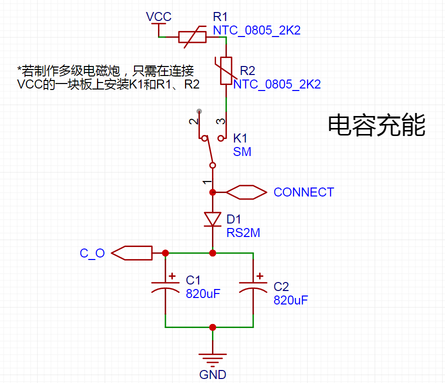
[Capacitor Charging]
This circuit uses two NTC thermistors for current limiting to prevent contact sparks within the switch and extend its lifespan. However, since a 2A microswitch is used, it's also possible to omit the NTC thermistors and directly short-circuit their contacts.
When K1 on the high-voltage power supply circuit board is triggered, VCC will connect to the CONNECT network of each stage of the circuit board via the two NTC thermistors. Therefore, in the [Capacitor Charging] circuit, only K1, R1, and R2 need to be installed on the circuit board connected to the high-voltage power supply (VCC). It's recommended to install them on the first stage; if installed on a later stage, K1 may be obstructed, making it inconvenient to use.
[Voltage Indication]
Two S8050 transistors are used in the two high-voltage indicator circuits on the left connected to capacitors to avoid excessive power consumption caused by direct capacitor connection and to prevent the LED from ignoring voltage fluctuations. The indicator light is not lit when the voltage is low and too bright when the voltage is high
because the indicator circuit is directly connected to the two ends of the capacitor. Therefore, it can also be used as a discharge indicator. When the voltage is greater than about 10V, the red light is on, indicating that the capacitor is charging or the voltage has not been fully discharged. When the voltage is greater than about 220V, the green light is on, indicating that the preset voltage of 250V has been reached (the voltage is preset to 250V in the circuit design, but it can actually be higher or lower). An external 500V LED voltmeter can also be connected as a voltage indicator.
The blue indicator light on the right is used to indicate that the 12V power supply is normal.

[Capacitor Discharge]
The purpose of this part of the circuit is to prevent the high voltage stored in the capacitor from injuring people
when the capacitor voltage is not fully discharged but is not emitting. When the capacitor voltage is 250V, after the discharge switch is turned on, the voltage across the capacitor drops to a safe voltage for the human body after 25 seconds. After the switch is turned on for 40 seconds, the capacitor voltage drops to about 10V.

[Photoelectric Signal]
LED4 is an infrared emitter, and LED5 is an infrared receiver. When LED5 receives infrared light, its resistance is close to 0, and the voltage between the base and emitter of Q3 is too low, causing it to cut off. PC817 does not trigger, and the voltage in the Q6_Control network is 0V at this time. When the shell blocks the infrared light, the resistance of LED5 rises sharply. At this time, the base of Q3 is at a high potential, Q3 conducts, LED6 is lit as an indicator light, and the internal LED of PC817 also lights up simultaneously. Pin 43 conducts, and the voltage in the Q6_Control network is close to 12V.

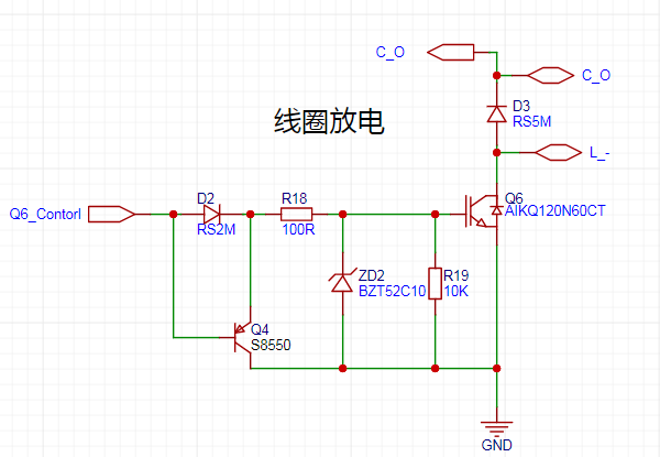
[Coil discharge]
When the Q6_Control network is high, Q4 does not conduct and discharge because the BE stage is high. ZD2 controls the voltage at 10V, so there will be a 10V voltage between the GE stages of Q6. When the Q6_Control network is low, the base stage of Q4 is at a low potential, the CE stage conducts, and the voltage between the GE stages of Q6 is quickly discharged. Because there is a very small voltage drop between the CE stages of Q4, the voltage between the GE stages of Q6 cannot be completely discharged. Therefore, a 10K resistor R19 is added to ensure complete discharge.
PCB layout:
The largest core components—capacitors, coils, and IGBTs—as well as two relatively large connectors are placed on the back of the PCB. The larger K1 on the front only needs to be installed in the first stage (the first stage is recommended), which makes it easier to build multiple stages. The
upper part is the control signal generation part of the circuit.
The upper right part is the charging control circuit. The lower part
is... The discharge circuit uses six 2W boost resistors. At 250V, the actual operating power is slightly over 11W.
The left side shows the voltage monitoring circuit.
PCB dimensions: 5.55cm * 5.4cm.

Operation
:
First, switch the discharge switch to the OFF position. Then press K1 to charge the capacitor. When the voltage reaches the preset voltage, release K1 and switch the launch switch to the ON position. If a projectile is blocking the photoelectric switch, it will fire immediately. Alternatively, you can turn on the launch switch first and then load a projectile. When the projectile blocks the photoelectric switch, it will fire automatically.
When not in use:
First, switch the launch switch to the OFF position. Then, switch the discharge switch to the ON position to discharge the capacitor. When the capacitor voltage is 250V, it will discharge for about 25 seconds to drop to a safe voltage for the human body, and for about 40 seconds to drop to 10V. Do not touch the capacitor terminals before the voltage drops below a safe voltage for the human body.
That
's the final product. What do you think?
(This dog ran over on its own.
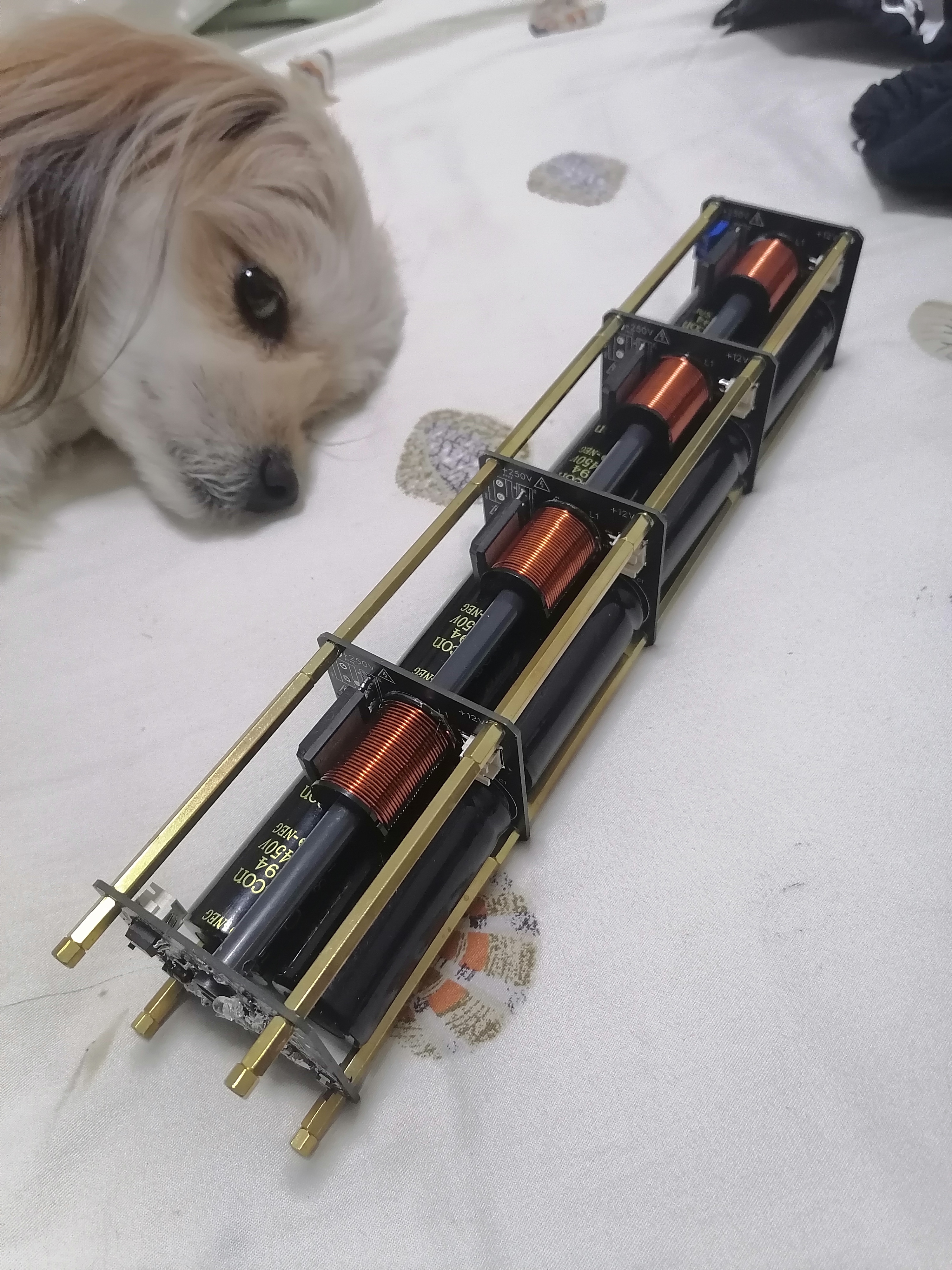

For speed measurement,
it's suggested to add a blank PCB without a power system after the final stage of the electromagnetic cannon. One reason is for a neater and more aesthetically pleasing design. Also, if you have an oscilloscope, you can use this PCB for speed measurement. The specific operation is as follows:
To achieve speed measurement using the last board, we need to solder the [photoelectric signal] circuit on this last PCB.

The author left two pads labeled [T+] and [T-] on the left side of this circuit. When a shell blocks the infrared receiver from receiving infrared light, the emitter of Q3 will be at a high level, with the voltage being the diode voltage drop at the PC817 control terminal plus the voltage drop of LED6, approximately 4V~4.5V. These two points are directly connected to the positive terminal of LED6 and pin 2 of PC817.
Modulating the oscilloscope to DC pulse detection mode allows you to measure the duration of this high level, which is the time it takes for the shell to travel the distance of the shell's length (I used a 20mm shell). Then you can...) The projectile's velocity can be calculated using the middle school equation v=s/t. For example,
if the projectile is 20mm long (0.02m) and the high-level signal lasts 10ms (0.01s), then the projectile's velocity would be 0.02m/0.01s = 2m/s.
However, this method has some errors and is slightly cumbersome. Those with the means can directly purchase an electromagnetic railgun velocity measurement module; this is merely a more economical reference solution.
Regarding the next generation
, since I'm about to enter high school, I may not have much time to complete its development in the next three years.
However, I've already envisioned the framework for the next two generations. Therefore, the next generation should be released by me after graduating high school and having some free time. Of course, if everyone supports this project, it might be released by me during my three years of high school, but I hope this article can be helpful to those just starting out in electronics. The next generation, the second generation, the third generation... will be developed by everyone who loves learning. The current generation of open source
still has many areas for improvement. Here are my thoughts briefly for those interested:
The structure still uses a four-copper-pillar design, but the first stage is now a ZVS power board/control board. The +12V copper pillar is replaced with a signal copper pillar. The subsequent stages only receive +12V power after the start switch on the first-stage power board is turned on. The switch for the subsequent stages
is removed; it is in the on state when it receives 12V, eliminating the need to turn on each transmitter switch individually.
Consider merging the CONNECT network directly with the C+ network. This would allow you to draw only the voltage indicator circuit on the first-stage power board
, eliminating unnecessary coil discharge circuits. Just make sure not to charge it when not in use, which would allow for a smaller size.
Also, replace the two capacitors with a single, larger-capacity flash capacitor. The specific placement is not yet well-planned.
It would be best to further optimize the capacitor charging limit circuit on the first stage.
Change the IGBT from through-hole to surface-mount, instead of blindly following trends. I need high current parameters for IGBTs. I'm looking for high-performance, cost-effective, and suitable
options. After modifications, the entire circuit only has a capacitor charging limit circuit, voltage indicator circuit, and two control switches in the first stage. The subsequent stage circuits are much simpler and smaller.
Regarding safety, I haven't found a safer or more convenient method than using insulating heat-shrink film for side insulation and insulating silicone for insulation of the first and last high-voltage lines. If you have better ideas, please share them in the comments section.
If you are interested in electromagnetic guns or electronic circuits but lack electronics knowledge, I recommend watching the videos of a teacher on Bilibili, 【多多百科】. This teacher was my introductory teacher for electromagnetic guns and electronics. He explains things while demonstrating, and his explanations are easy to understand. Many of his videos were very helpful for me when I first started learning about electronics.
Finally, I strongly suggest using PVC insulating heat-shrink film for side insulation and insulating silicone for insulation of the first and last high-voltage lines to eliminate safety hazards. Safety first!!!
*Only version V3.0 is correct in the circuit diagrams below. The other versions are discarded products from recent brainstorming sessions, and their PCB structure and layout have some issues. Therefore, not much time was spent revising the circuits. There are many errors in the circuit diagrams and PCB layouts. Interested students can take a look.


 京公网安备 11010802033920号

 IDT54FCT823ATQB


