Project Analysis:
This project is based on the Liangshan School design of a dual-channel oscilloscope
to achieve the following functions:
1. Dual-channel acquisition ;
2. DAC waveform generation;
3. Dial button control;
4. Screen touch control.
Overall Hardware Block Diagram:

This project is based on an official case study, which is as follows: [Oscilloscope Expansion Board].
My work includes:
1. Drawing a dual-channel acquisition circuit based on the official single-channel acquisition circuit
; 2. Drawing a screen touch circuit to replace button operation;
3. Removing the tactile buttons and retaining the dial buttons;
4. Using screen touch + dial buttons to complete human-computer interaction;
5. Adding a power supply interface;
6. Designing the PCB based on the drawn schematic.
7. Solder and debug the oscilloscope.
8. Complete the dual-channel oscilloscope code
schematic design. Instructions:
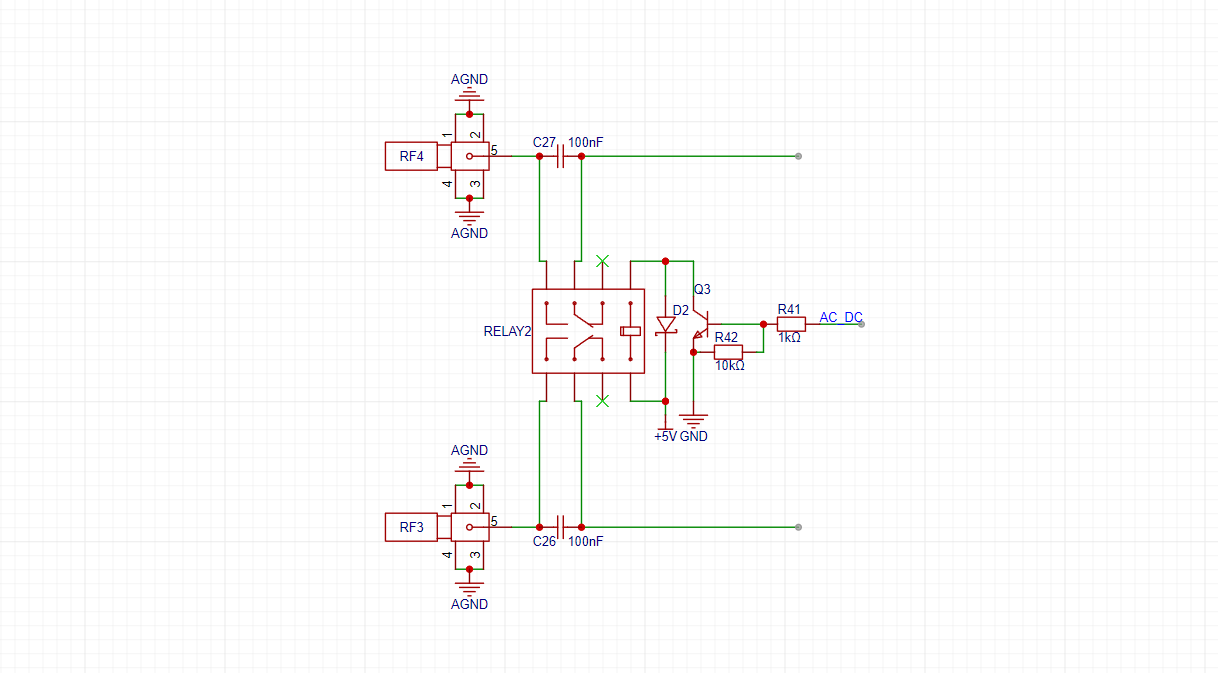
1. AC/DC Coupling Circuit:
This project uses a relay to simultaneously control the AC/DC coupling of two ADC acquisition circuits. Switching the relay switch is achieved by changing the GPIO level.
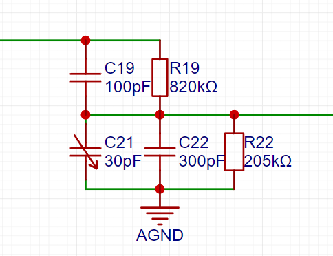
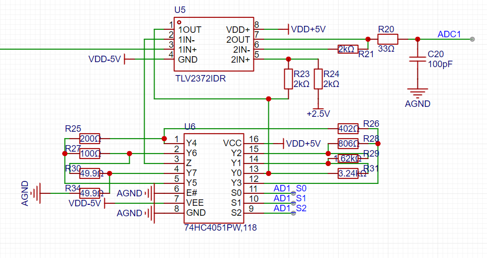
2. Voltage Divider Circuit, Programmable Operational Amplifier Signal Processing Circuit, and Waveform Generator Output Voltage Follower Circuit:
These three circuits are all based on official examples and will not be explained further here. Please refer to the official documentation [Oscilloscope Expansion Board].

3. Power Supply Section:
The level conversion in the power supply section is based on official examples. I won't go into too much detail here
. Based on the official documentation, I added a power supply interface because when using the official oscilloscope extension version, the power supply interface interfered with the waveform acquisition and output channels, preventing normal operation. In this project, after modifying it to use the waveform acquisition channel, one channel became unusable. Therefore, I added a power supply interface to ensure stable operation of both channels.
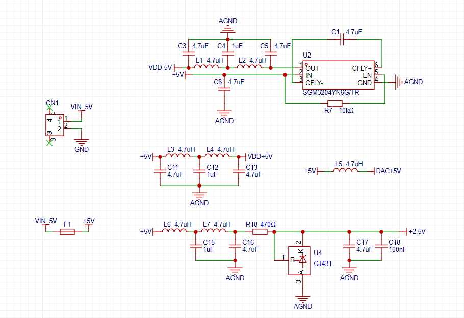
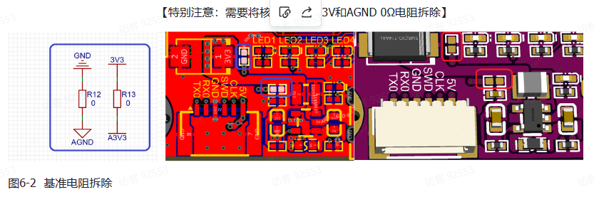
Also, please note that the oscilloscope uses a +2.5V ADC reference, but the Liangshanpai version uses a 3.3V reference. Therefore, the A3.3V and AGND 0Ω resistors in the Liangshanpai version need to be removed. The official documentation specifically notes the following:
4. Screen Circuit:
This project uses a 2.4-inch SPI screen. A touch circuit is added to the official display circuit to achieve touch interaction on the oscilloscope. Both display and touch use SPI communication.

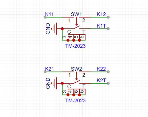
5. Button Circuit:
This project uses two DIP switches and screen touch to achieve human-computer interaction on the oscilloscope.
PCB Design Description:
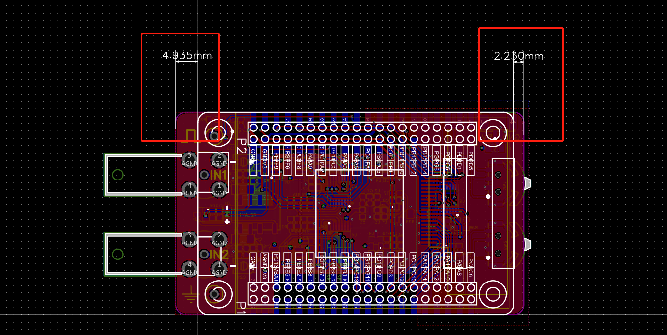
This project requires the placement of many components, so I lengthened the board during the design process. The width is consistent with the core board of Liangshanpai, as shown in the figure below.
The PCB layout is relatively compact, which significantly impacts routing. Therefore, this project ultimately adopted a 4-layer board design. Inner layer 1 is used as an analog ground plane. Inner layer 2 is only connected to some power and signal lines due to concerns about interference with analog signals (this is my first time drawing this, and I'm not sure if it will cause interference. If any experts can see this and explain the relevant knowledge, that would be excellent; please don't criticize).
In this project, two ADC detection probes are brought out, along with waveform generation test points and analog ground test points. The test loop is used for the waveform generation test point and the simulated ground test point, which facilitates the connection and testing of the oscilloscope probe .

Also, the component layout is relatively dense, making soldering slightly more troublesome.
Software instructions:
1. Initialization of dual-channel ADC
The two ADCs are PA1-ADC0CH1 and PF7-ADC2CH5. The acquisition idea is: the timer triggers ADC acquisition, DMA automatically stores the data, and when the data acquisition is halfway completed or completed, the DMA interrupt is triggered, and the acquired data is displayed in waveform form
in the ADC initialization function. PA1 uses the same pin as the official example and does not need to be modified. Only the PF7 part needs to be added.

Acquisition interrupt function of ADC2CH5
2. AC/DC switching and sampling rate switching control

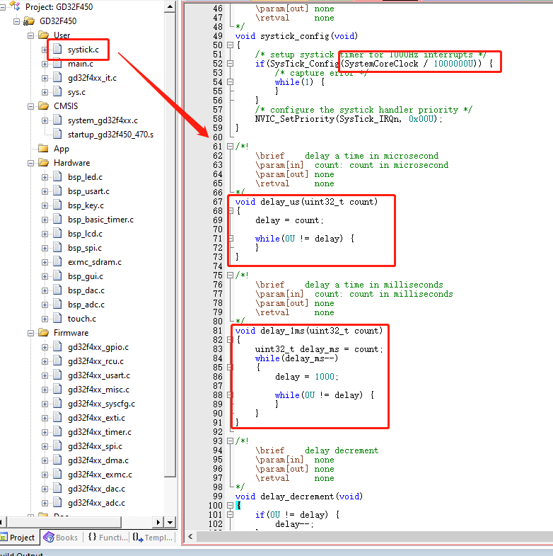
3. Implementation of microsecond delay function
First, modify the systick.c function and modify the value of the systick clock reload register. The original value is system clock/1000. In this case, the practical interval of each interrupt entry is 1ms, so the original file only has the millisecond delay function. Modifying this value to system clock/1000000 changes the interrupt time to 1µs. Simultaneously, the original millisecond delay function is modified, thus completing the microsecond delay function implementation.
4. Touch Function Porting:
The touch chip used in this project is XPT2046. Screen vendors provide touch functions for XPT2046, but these are functions applied to ST chips and require GD porting.
The provided touch routines use software SPI, so this project also uses software SPI. The microsecond function implementation in the previous step mainly applies to the touch software SPI communication.
Due to batch differences and other reasons, the default calibration parameter values of the touchscreen may cause inaccurate touch recognition. It is recommended to calibrate before use; it is not recommended to directly use fixed default calibration parameters. The touch function initialization is shown in the figure below. The Adjust function determines whether to use the original parameters or manual calibration to obtain parameters.
It is recommended to use manual calibration first to obtain more accurate parameters (output via serial port). Modify the program according to these parameters and then disable manual calibration.

Touch coordinate acquisition is shown in the figure below, with two additional parameters added. The state machine is used to support single touches, preventing multiple triggers of corresponding functions due to a single touch.

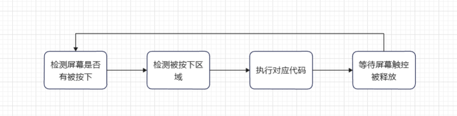
A brief introduction to the touch logic in this project: First, it loops to check if the screen is pressed. When pressed, it checks the pressed screen area. If a corresponding touch function exists within that area, the corresponding code is executed. After execution, it waits for the touch to be released. Once released, it returns to the beginning, implementing the loop detection. The logic block diagram is shown below.
The touch response function in the non-paused state is shown below.

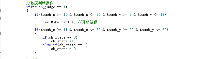
The touch response function in the paused state is shown below.
5. Overall Function Implementation:
The overall functions of this project are modified from the official example to
implement the following functions:
Implementing touch operations, including pausing/starting waveform acquisition, switching between upper and lower edges, AC/DC switching, amplification factor switching, sampling speed switching, waveform type switching, FFT switching, and channel information display switching in the paused state.
Dual-dial function adaptation: The original example's dial control function is not suitable for dual-channel acquisition, so this project, based on dual-channel acquisition, implements the dual-dial control function.
Overall functionality adapted to a dual-channel oscilloscope.
#include "gd32f4xx.h"
#include "systick.h"
#include
#include "main.h"
#include "bsp_led.h"
#include "sys.h"
#include "bsp_usart.h"
#include "bsp_key.h"
#include "bsp_basic_timer.h"
#include "bsp_lcd.h"
#include "bsp_spi.h"
#include "bsp_gui.h"
#include "exmc_sdram.h"
#include "bsp_dac.h"
#include "bsp_adc.h"
#include "touch.h"
#include "arm_math.h"
// ADC data acquisition pointer
uint16_t *adc_tmp;
uint16_t *adc_tmp1;
// FFT variable
#define FFT_LENGTH 1024 // FFT length, default is 1024 points
float fft_inputbuf[FFT_LENGTH*2]; // FFT input array
float fft_outputbuf[FFT_LENGTH]; // FFT output array
arm_cfft_radix4_instance_f32 scfft;
// FFT display processing
float max_fft;
uint16_t fft_number;
// uint16_t fft_n; // Scaling ratio
// Frequency domain display state
uint8_t fft_show_state = 1; // Default 1 displays probe 1, 2 displays probe 2, 0 does not display
uint16_t Lase_Trigger_number, Lase_Trigger_number1;
uint8_t show_updata;
uint16_t data_tmp;
// Shift wheel button settings
uint8_t keya_set=0;
uint8_t keya_number=3;
uint8_t keyb_set=0;
uint8_t keyb_number=4;
// Touch coordinates and touch state
uint16_t touch_x;
uint16_t touch_y;
uint8_t touch_state = 0; // 0 represents the screen is not touched, 1 represents the screen is touched
uint8_t touch_judge = 0;
/*!
rief main function
param[in] none
param[out] none
etval none
*/
int main(void)
{
uint32_t i;
nvic_priority_group_set(NVIC_PRIGROUP_PRE2_SUB2); // Priority grouping
systick_config();
led_gpio_config(); // Led initialization
key_gpio_config(); // Key initialization
usart_gpio_config(9600U);
// SRAM initialization
exmc_synchronous_dynamic_ram_init(EXMC_SDRAM_DEVICE0);
// LCD initialization
LCD_Init();
delay_1ms(50);
Spi2_Dma_Init();
Lcd_Gram_Fill(Show_GramA,GRAM_BLACK); // Write color data to buffer
LCD_Show_Gram(Show_GramA);
while(Lcd_Show_Over);
LCD_BLK_Set(); // Enable backlight
delay_1ms(10);
Lcd_Gram_Fill(Show_GramA,GRAM_BLACK);
Lcd_Gram_Fill(Show_GramB,GRAM_BLACK);
// Enable timer for fixed screen refresh
Lcd_Show_Time();
// Waveform output
dac_config();
Dac_Show_Wav(wav_number);
Dac_Time_Hz(wav_Fps);
// ADC acquisition
adc_config();
adc_setio_init();
alternating_direct_set(ac_dc);
gather_rate_set(gather_rate);
adc_speed_set(adc_speed);
TP_Init();
//// FFT initialization of scfft structure
arm_cfft_radix4_init_f32(&scfft,FFT_LENGTH,0,1);
// Draw function icons
POINT_COLOR=GRAM_WHITE; // Brush color
for(i=0;i
POINT_COLOR=GRAM_YELLOW; //Pen color
Lcd_Show_Data(keya_number);
POINT_COLOR=GRAM_GREEN; //Pen color
Lcd_Show_Data(keyb_number);
POINT_COLOR=GRAM_WHITE; //Pen color
while(1)
{
//Timer loops to refresh fixed data
while(Lcd_Show_Over);
if(show_updata)
{
show_updata=0;
Show_Star=1; //Start this frame flag
while(Show_Star); //Wait for frame processing
}
//Touch detection, only supports single touch, does not support continuous touch
TP_Scan(0);
if(touch_state == 0)
{
if(tp_dev.sta&TP_PRES_DOWN)//A touch is pressed
{
delay_1ms(1);//Necessary delay, otherwise it will always think that a button is pressed.
if((tp_dev.x[0]=1)&&(tp_dev.y[0]=1))
{
touch_x = tp_dev.x[0];
touch_y = tp_dev.y[0];
touch_judge = 1;
//printf("X:%d, Y:%d
", tp_dev.x[0], tp_dev.y[0]);
}
}
}
if(tp_dev.sta&TP_PRES_DOWN)//touch is pressed
touch_state = 1;
else
touch_state = 0;
if(adc_power)
{
//wait for data acquisition to complete
while(!adc_dma_ok);
adc_dma_ok=0;
//configure pointer to add calculation buffer DMA sampling speed too fast
if(adc_dma_AB) adc_tmp = adc_value + adc_buff_2x;
else adc_tmp = adc_value ;
if(adc_dma_AB1) adc_tmp1 = adc_value1 + adc_buff_2x;
else adc_tmp1 = adc_value1;
for(i=0;i
{
adc_buff[i] = adc_tmp[i];
adc_buff1[i] = adc_tmp1[i];
}
if(fft_show_state == 1)
{
//FFT operation
for(i=0;i
{
fft_inputbuf[2*i]=adc_buff[i];//Generate the real part of the input signal
fft_inputbuf[2*i+1]=0;//The imaginary part is all 0
}
arm_cfft_radix4_f32(&scfft,fft_inputbuf);//FFT calculation (radix 4)
arm_cmplx_mag_f32(fft_inputbuf,fft_outputbuf,FFT_LENGTH);//Calculate the magnitude by taking the modulus of the complex result
fft_outputbuf[0] = 0;//The first value is very large, so it is discarded here
//Calculate the maximum FFT point
max_fft = 0;
fft_number=0;
for(i=0;i
{
if(fft_outputbuf[i] > max_fft)
{
max_fft = fft_outputbuf[i];
fft_number = i;
}
}
//Automatically evaluate the FFT scaling level
fft_n = max_fft/150 + 1; //Only display 150 scales
for(i=0;i
{
Show_LinB[i]=(fft_outputbuf[i]/fft_n +27);
if(Show_LinB[i] > 227) Show_LinB[i]=227-8;
else if(Show_LinB[i]
else Show_LinB[i]=Show_LinB[i]-8;
}
//FFT frequency estimation
fft_fps = (2000000 / (0x01
}
else if(fft_show_state == 2)
{
//FFT operation
for(i=0;i
{
fft_inputbuf[2*i]=adc_buff1[i];//Generate the real part of the input signal
fft_inputbuf[2*i+1]=0;//The imaginary part is all 0
}
arm_cfft_radix4_f32(&scfft,fft_inputbuf);//FFT calculation (radix 4)
arm_cmplx_mag_f32(fft_inputbuf,fft_outputbuf,FFT_LENGTH);//Calculate the magnitude by taking the modulus of the complex number of the operation result
fft_outputbuf[0] = 0;//The first value is very large, so it is discarded here
//Calculate the maximum FFT point
max_fft = 0;
fft_number=0;
for(i=0;i
{
if(fft_outputbuf[i] > max_fft)
{
max_fft = fft_outputbuf[i];
fft_number = i;
}
}
//Automatically evaluate the FFT scaling level
fft_n = max_fft/150 + 1; // Only display 150 ticks
for(i=0;i
{
Show_LinB[i]=(fft_outputbuf[i]/fft_n +27);
if(Show_LinB[i] > 227) Show_LinB[i]=227-8;
else if(Show_LinB[i]
else Show_LinB[i]=Show_LinB[i]-8;
}
// FFT frequency estimation
fft_fps = (2000000 / (0x01
}
////// Set value judgment Trigger rising and falling edges
Trigger_number=0;
max_data = 2048+(Trigger-Level)*16;
if(wav_trigger)
{
for(i=lin_stat_set;i
{
if(adc_tmp[i]
{
for(;i
{
if(adc_tmp[i] > max_data)
{
Trigger_number=i-lin_stat_set;
break;
}
}
break;
}
}
}
else
{
for(i=lin_stat_set;i
{
if(adc_tmp[i] > max_data+25)
{
for(;i
{
if(adc_tmp[i]
{
Trigger_number=i-lin_stat_set;
break;
}
}
break;
}
}
}
Trigger_number1=0;
max_data = 2048+(Trigger1-Level1)*16;
if(wav_trigger)
{
for(i=lin_stat_set;i
{
if(adc_tmp1[i]
{
for(;i
{
if(adc_tmp1[i] > max_data)
{
Trigger_number1=i-lin_stat_set;
break;
}
}
break;
}
}
}
else
{
for(i=lin_stat_set;i
{
if(adc_tmp1[i] > max_data+25)
{
for(;i
{
if(adc_tmp1[i]
{
Trigger_number1=i-lin_stat_set;
break;
}
}
break;
}
}
}
//Cache scaling and cropping import
for(i=0;i
{
Show_LinA[i]=((adc_buff[i+Trigger_number] + 0x08)>>4) + Level;//
if(Show_LinA[i] > 227) Show_LinA[i]=227-8;
else if(Show_LinA[i]
else Show_LinA[i]=Show_LinA[i]-8;
Show_LinA1[i]=((adc_buff1[i+Trigger_number1] + 0x08)>>4) + Level1;
if(Show_LinA1[i] > 227) Show_LinA1[i]=227-8;
else if(Show_LinA1[i]
else Show_LinA1[i]=Show_LinA1[i]-8;
}
//Display data
if(Show_AB) Lcd_Show_Wav(Show_GramA);
else Lcd_Show_Wav(Show_GramB);
//Touch judgment operation
if(touch_judge == 1)
{
//Start pause
if(touch_x >= 10 & touch_x = 2 & touch_y
{
Lase_Trigger_number = Trigger_number+1;
Key_Make_Set(0); // Start Pause
}
// Falling Edge Rising Edge
if(touch_x >= 125 & touch_x = 2 & touch_y
{
if(wav_trigger)
Key_Make_Set(4);
else
Key_Make_Set(5);
}
// ACDC
if(touch_x >= 150 & touch_x = 2 & touch_y
{
Key_Make_Set(6); // ACDC
}
// Increase Magnification
if(touch_x >= 175 & touch_x = 2 & touch_y
{
Key_Make_Set(11);
}
// Decrease Magnification
if(touch_x > 191 & touch_x = 2 & touch_y
{
Key_Make_Set(10);
}
// Decrease Sampling Speed
if(touch_x >= 240 & touch_x = 2 & touch_y
{
Key_Make_Set(13); //Increase waveform type
}
//Increase sampling speed
if(touch_x > 261 & touch_x = 2 & touch_y
{
Key_Make_Set(14); //Increase waveform type
}
//Change waveform type
if(touch_x >= 10 & touch_x = 222 & touch_y
{
Key_Make_Set(23); //Increase waveform type
}
//FFT function
if(touch_x >= 100 & touch_x = 222 & touch_y
{
Key_Make_Set(29); //FFT
}
}
//Dial A
if(key[3] == Key_Time)
{
if(keya_set)
{
key[3] = Key_No; //Need to release again
Lcd_Show_Data(keya_number);
if(keya_number
POINT_COLOR=GRAM_YELLOW; //Pen color
Lcd_Show_Data(keya_number);
POINT_COLOR=GRAM_WHITE; //Pen color
}
else
{
if(keya_number==5 || keya_number==6 || keya_number==8) key[3]--; //No need to release
else key[3] = Key_No; //Need to release again
POINT_COLOR=GRAM_YELLOW; //Pen color
Key_Make_Set(keya_number*3 + 2); //Subtract 1
POINT_COLOR=GRAM_WHITE; //Pen color
}
}
if(key[4] == Key_Time)
{
key[4] = Key_No; //Need to release again
keya_set = !keya_set;
}
if(key[5] == Key_Time)
{
if(keya_set)
{
key[5] = Key_No; //Need to release again
Lcd_Show_Data(keya_number);
if(keya_number) keya_number--;
POINT_COLOR=GRAM_YELLOW; //Pen color
Lcd_Show_Data(keya_number);
POINT_COLOR=GRAM_WHITE; //Pen color
}
else
{
if(keya_number==5 || keya_number==6 || keya_number==8) key[5]--; //No need to release
else key[5] = Key_No; //Need to release again
POINT_COLOR=GRAM_YELLOW; //Pen color
Key_Make_Set(keya_number*3 + 1); //Decrement by 1
POINT_COLOR=GRAM_WHITE; //Pen color
}
}
//Dial B
if(key[6] == Key_Time)
{
if(keyb_set)
{
key[6] = Key_No; // Need to be released again
Lcd_Show_Data(keyb_number);
if(keyb_number
POINT_COLOR=GRAM_GREEN; // Pen color
Lcd_Show_Data(keyb_number);
POINT_COLOR=GRAM_WHITE; // Pen color
}
else
{
if(keyb_number==5 || keyb_number==6 || keyb_number==8) key[6]--; // No need to release
else key[6] = Key_No; // Need to be released again
POINT_COLOR=GRAM_GREEN; // Pen color
Key_Make_Set(keyb_number*3 + 2); // Subtract 1
POINT_COLOR=GRAM_WHITE; // Pen color
}
}
if(key[7] == Key_Time)
{
key[7] = Key_No; // Need to be released again
keyb_set = !keyb_set;
}
if(key[8] == Key_Time)
{
if(keyb_set)
{
key[8] = Key_No; // Need to release again
Lcd_Show_Data(keyb_number);
if(keyb_number) keyb_number--;
POINT_COLOR=GRAM_GREEN; // Pen color
Lcd_Show_Data(keyb_number);
POINT_COLOR=GRAM_WHITE; // Pen color
}
else
{
if(keyb_number==5 || keyb_number==6 || keyb_number==8) key[8]--; // No need to release
else key[8] = Key_No; // Need to release again
POINT_COLOR=GRAM_GREEN; // Pen color
Key_Make_Set(keyb_number*3 + 1); // Decrease by 1
POINT_COLOR=GRAM_WHITE; // Pen color
}
}
// Update display
show_updata=1;
}
else
{
//Determine the maximum/minimum value
min_data=0xffff;
min_data1=0xffff;
max_data=0;
max_data1=0;
for(i=0;i
{
if(adc_tmp[i+Trigger_number]
if(adc_tmp[i+Trigger_number]> max_data) max_data=adc_tmp[i+Trigger_number];
if(adc_tmp1[i+Trigger_number1]
if(adc_tmp1[i+Trigger_number1]> max_data1) max_data1=adc_tmp1[i+Trigger_number1];
}
if(Lase_Trigger_number != Trigger_number)
{
Lase_Trigger_number = Trigger_number;
//Cache import
for(i=0;i
{
Show_LinA[i]=((adc_tmp[i+Trigger_number] + 0x08)>>4) + Level;
//Show_LinA[i]=((adc_tmp[i+Trigger_number] )>>4) + Level;
if(Show_LinA[i] > 227) Show_LinA[i]=227-8;
else if(Show_LinA[i]
else Show_LinA[i]=Show_LinA[i]-8;
}
}
if(Lase_Trigger_number1 != Trigger_number1)
{
Lase_Trigger_number1 = Trigger_number1;
//Cache import
for(i=0;i
{
Show_LinA1[i]=((adc_tmp1[i+Trigger_number1] + 0x08)>>4) + Level1;
//Show_LinA[i]=((adc_tmp[i+Trigger_number] )>>4) + Level;
if(Show_LinA1[i] > 227) Show_LinA1[i]=227-8;
else if(Show_LinA1[i]
else Show_LinA1[i]=Show_LinA1[i]-8;
}
}
// Display data
if(Show_AB)
{
// Draw waveform
Lcd_Show_Wav(Show_GramA);
}
else
{
// Draw waveform
Lcd_Show_Wav(Show_GramB);
}
// Update display
show_updata=1;
// Touch judgment operation
if(touch_judge == 1)
{
if(touch_x >= 10 & touch_x = 2 & touch_y
{
Key_Make_Set(0); // Start pause
}
if(touch_x >= 11 & touch_x = 20 & touch_y
{
if(ch_state == 0)
ch_state =1;
else if(ch_state == 1)
ch_state = 0;
}
}
//Toggle wheel A
if(key[3] == Key_Time)
{
key[3]--;
if(Trigger_number
}
if(key[4] == Key_Time)
{
key[4] = Key_No; //Need to be released again
}
if(key[5] == Key_Time)
{
key[5]--;
if(Trigger_number > 5) Trigger_number-=5;
else if(Trigger_number) Trigger_number = 0;
else;
}
//Toggle wheel B
if(key[6] == Key_Time)
{
key[6]--;
if(Trigger_number1
}
if(key[7] == Key_Time)
{
key[7] = Key_No; //Need to be released again
}
if(key[8] == Key_Time)
{
key[8]--;
if(Trigger_number1 > 5) Trigger_number1-=5;
else if(Trigger_number1) Trigger_number1 = 0;
else;
}
}
touch_judge = 0;
//delay_1ms(200);
}
}
//Screen refresh 50mS
void TIMER3_IRQHandler(void)
{
timer_interrupt_flag_clear(TIMER3, TIMER_INT_FLAG_UP);
if(Show_Star)
{
//LED1_TOGGLE();
Show_Star=0;
if(Show_AB)LCD_Show_Gram(Show_GramA);
else LCD_Show_Gram(Show_GramB);
Show_AB =!Show_AB;
}
//Dial A
if(KeyAUp) key[3] &= Key_Time;
else if(key[3]
else;
if(KeyAOn) key[4] &= Key_Time;
else if(key[4]
else;
if(KeyADown) key[5] &= Key_Time;
else if(key[5]
else;
//Dial B
if(KeyBUp) key[6] &= Key_Time;
else if(key[6]
else;
if(KeyBOn) key[7] &= Key_Time;
else if(key[7]
else;
if(KeyBDown) key[8] &= Key_Time;
else if(key[8]
else;
}
//ADC collection
void DMA1_Channel0_IRQHandler(void)
{
//LED3_TOGGLE();
adc_dma_ok=1;
if(dma_interrupt_flag_get(DMA1, DMA_CH0,DMA_INT_FLAG_HTF) == SET) adc_dma_AB=0;
else adc_dma_AB=1;
dma_interrupt_flag_clear(DMA1, DMA_CH0, DMA_INT_FLAG_FTF|DMA_INT_FLAG_HTF);
}
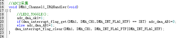
//ADC2 acquisition
void DMA1_Channel1_IRQHandler(void)
{
//LED2_TOGGLE();
adc_dma_ok1=1;
if(dma_interrupt_flag_get(DMA1, DMA_CH1,DMA_INT_FLAG_HTF) == SET) adc_dma_AB1=0;
else adc_dma_AB1=1;
dma_interrupt_flag_clear(DMA1, DMA_CH1, DMA_INT_FLAG_FTF|DMA_INT_FLAG_HTF);
}
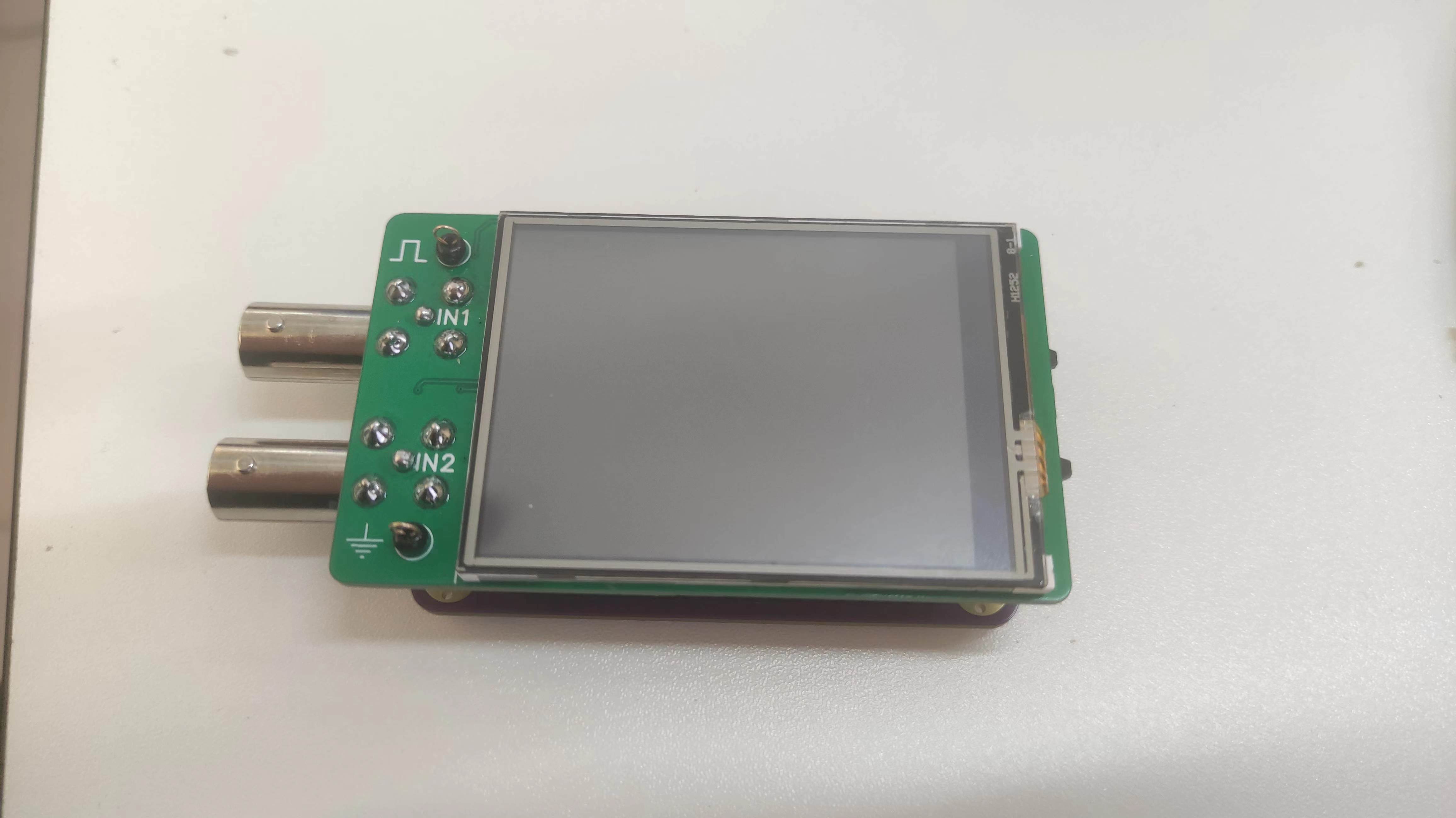
Physical demonstration instructions:
Front side

precautions
1. In the power supply section of the schematic design instructions, it is mentioned that the ADC reference source uses +2.5V, but the reference source used in Liangshanpai is 3.3V. Therefore, it is necessary to connect A3.3V and AGND in Liangshanpai. The 0Ω resistor was removed, otherwise it would be equivalent to short-circuiting 2.5V and 3.3V. However, I didn't initially notice this and didn't remove the 0Ω resistor. But in this situation, the oscilloscope worked normally.
I believe the reason it worked normally is that the 0Ω resistor wasn't truly short-circuited; it still had some resistance. The voltage drop of 3.3-2.5=0.8V through the 0Ω resistor wasn't enough to burn out the circuit. Through actual power testing, I obtained the following data: Oscilloscope current 254.6mA (
0Ω resistor removed, 0Ω resistor
not removed
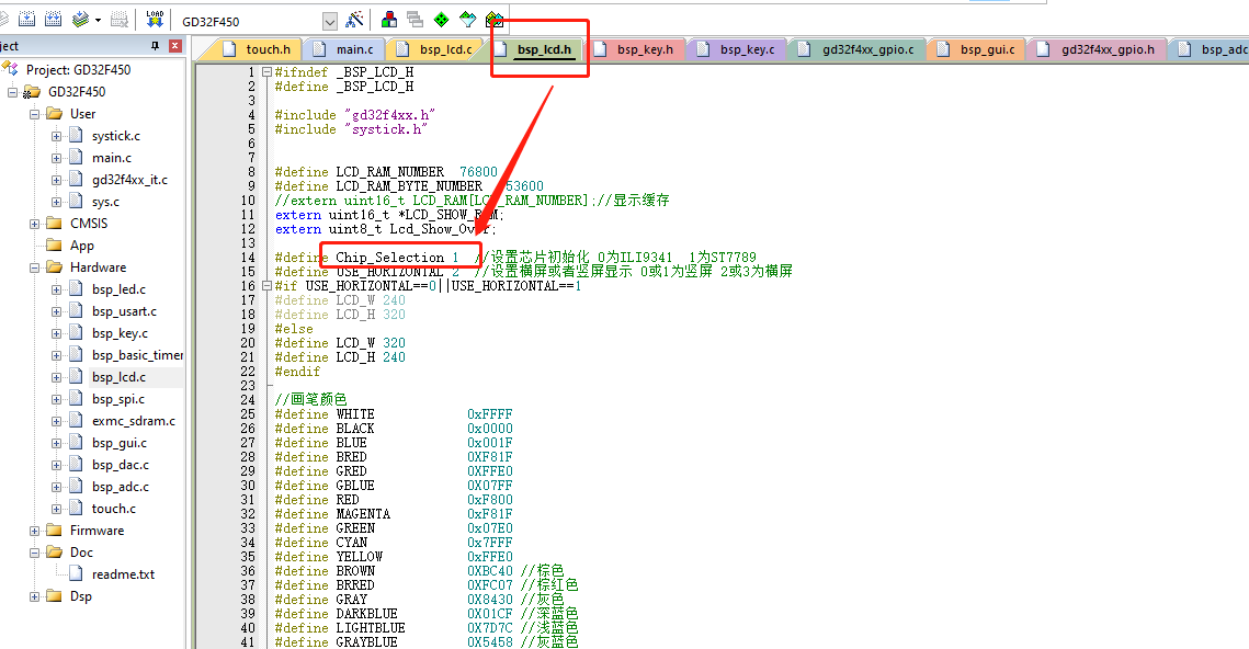
) . 125.4mA Test Equipment: Heze CC meter , but it is still not recommended to insert the oscilloscope extension board without removing the 0Ω resistor. If you must test it, please do so under safe conditions. 2. When using the oscilloscope probe, pay attention to the 1X and 10X ranges on the probe. Normally, the 1X range is sufficient. The 10X range will reduce the signal by a factor of ten and is generally not used. When using the oscilloscope, if you find that the acquired signal suddenly becomes very small, check if the oscilloscope probe is set to the 10X range. (Don't ask, I won't tell you that I accidentally set the wrong range and checked the entire circuit.) 3. The program can be directly compiled and burned. If it cannot be displayed normally after burning, it may be due to an error in the screen driver. Modify the Chip_Selection variable value in the bsp_lcd.h file according to your chip model. It supports ILI9341 and ST7789 screen drivers. Project Summary: I learned a lot through this project, summarized as follows: Liangshan School Hardware Circuit Knowledge

Analog circuit hardware knowledge,
analog circuit power supply design,
application of DIP switches,
use of 2.4-inch IPS screen,
analog circuit PCB design,
4-layer PCB design,
use of GD32F450/470, use of
TIME+DMA+ADC/DAC,
use of DSP library FFT,
UI interface design,
C language development knowledge,
system program development.
It was a very rewarding experience.
Reference links:
Liangshanpai Oscilloscope Extended Edition Materials,
[LCSC Liangshanpai] Introductory Tutorial Materials.


 京公网安备 11010802033920号

 NT90TPNASDC12VC


