Project Description:
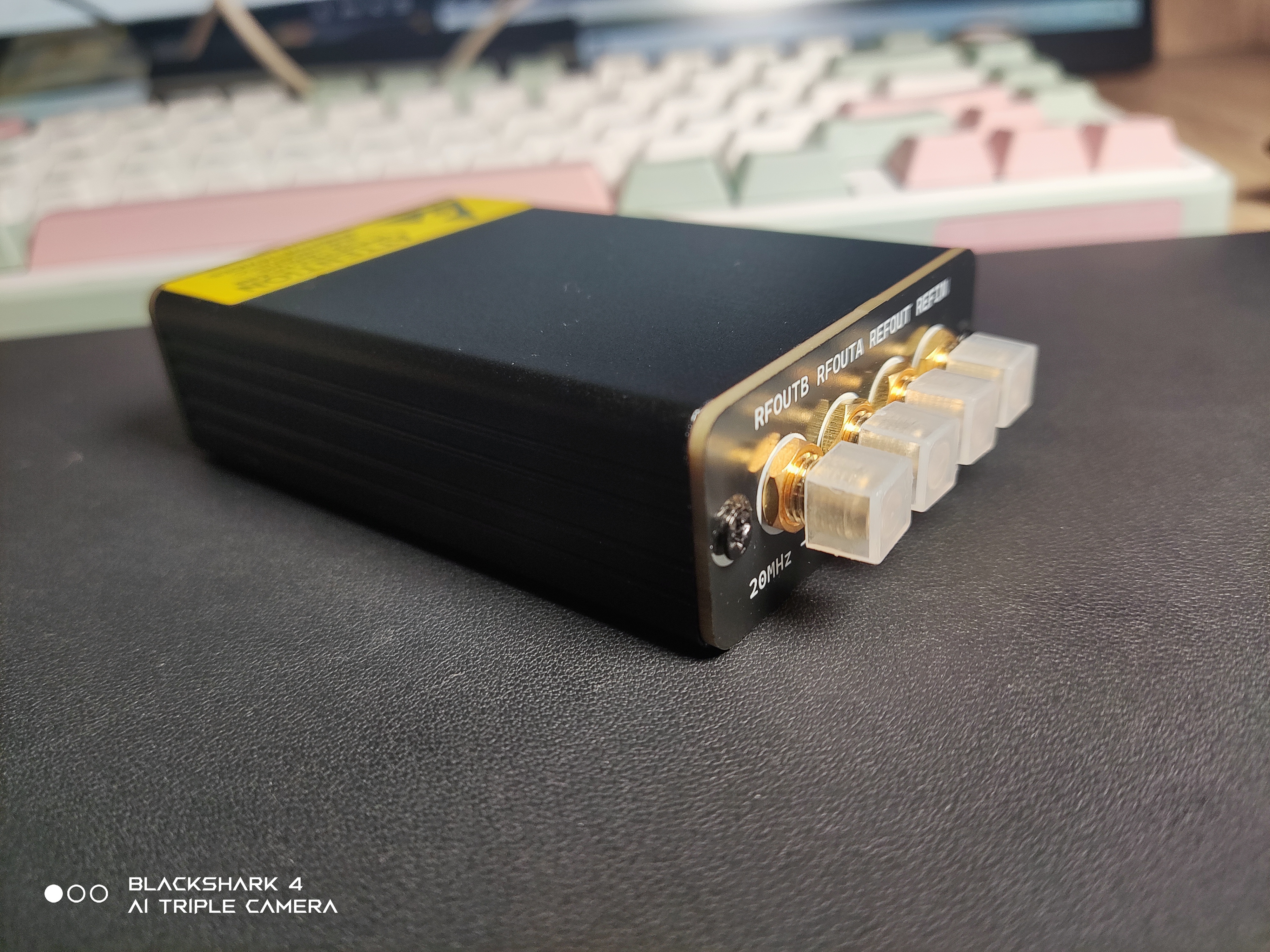
I've been working on a portable RF clock source for the past few days. It's very small, fits in one hand, and can be carried around in your pocket. It has dual-channel output, a frequency range of 20MHz to 9.8GHz, and a theoretical frequency resolution of 1Hz. For input, there's one reference input and one reference output, supporting the use of the onboard OCXO as a reference or locking an external reference. Control and power are handled via a Type-C port, making it plug-and-play. Currently, it uses serial port commands for control, with ten commands covering the basic functions. Future plans include building a host computer using QT for graphical configuration.
PS: QT is quite fun. I played around with it for two days and built a simple host computer, which can now graphically control the portable RF clock source. It's ready to use as soon as you connect the Type-C port to the computer, without needing to configure various registers separately.
Open Source License:
Commercial use is prohibited without the author's permission. Reproduction or citation must credit the original author and provide a project link.
Project Related Functions
: 1. Overall Resource Overview:
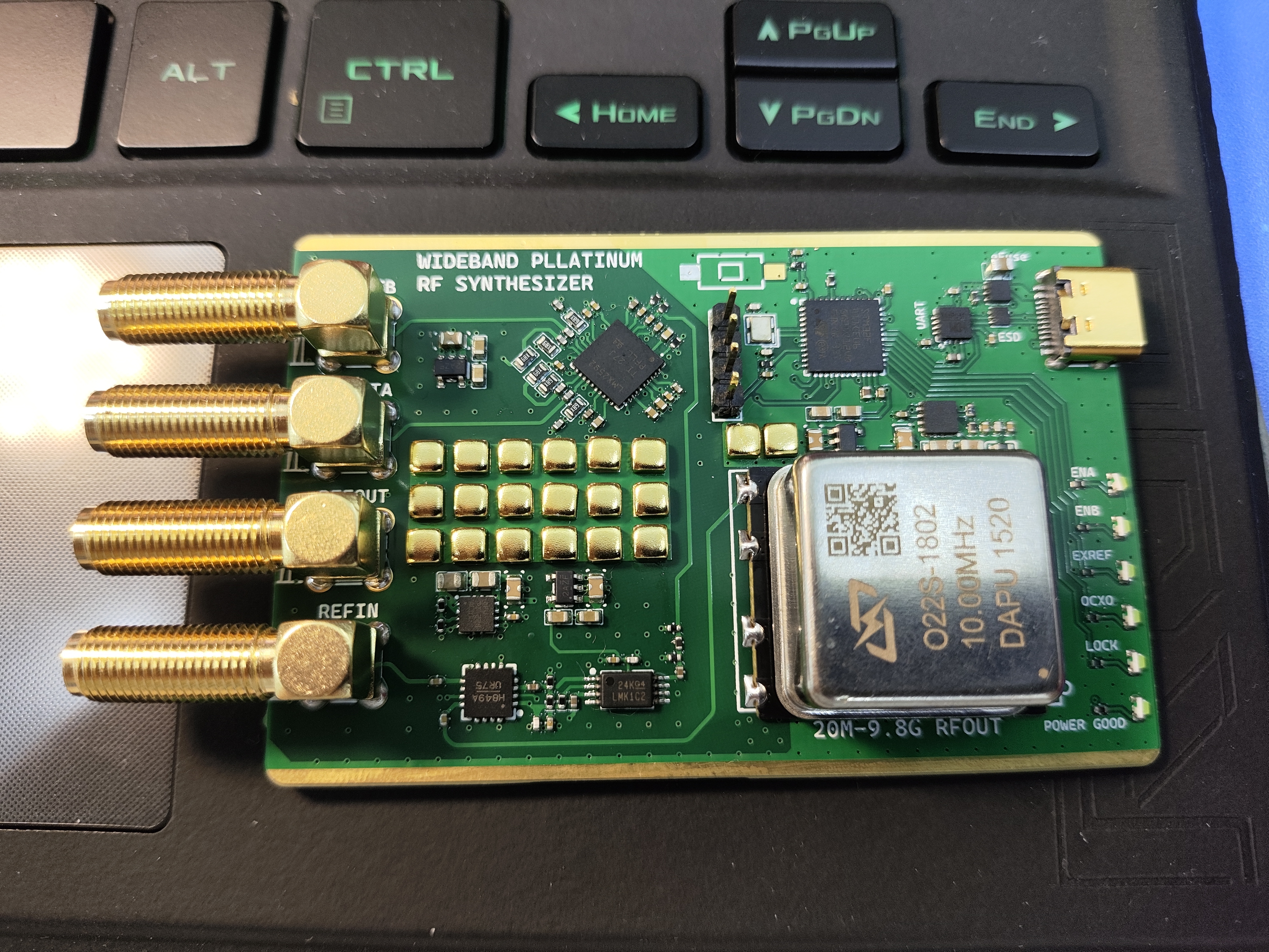
This RF source has an onboard OCXO with a default reference signal frequency of 10MHz. The onboard STM32F411 is used for control and communication with the host computer. All RF links are matched to 50Ω impedance. An onboard non-reflective RF switch is used for reference signal switching, supporting external reference signal input. An onboard low-jitter clock buffer is included, along with an additional reference signal output. This design incorporates an aluminum profile housing and PCB panel, encapsulating the PCB and components, making it more like a true pocket device.
2. TYPEC Interface:
Power supply and communication are handled using a single TYPEC port, requiring no driver and offering plug-and-play functionality (using the CH343P serial chip, which can run without a driver on most computers). For protection, the TYPEC interface includes ESD+common-mode filtering and EFUSE to prevent damage to the computer interface.
3. Power Management:
To reduce spurious signals from the fractional-division mode, a DC-DC power supply was not introduced. All power supplies utilize ultra-high PSRR, low-noise LDOs with feedthrough capacitors to achieve a cleaner power supply and introduce less noise. The power consumption during startup (preheating of the thermostatic crystal oscillator) is approximately 4W, and the stable power consumption during operation is approximately 2W-3W.
4. Thermostatic Crystal Reference Source:
The thermostatic crystal oscillator used is DAPU's O22S-1802 (new, approximately 50 RMB), which features high stability, low phase noise, and a typical phase noise value of -150dBc at 1KHz@10MHz, making it a relatively cost-effective option among new OCXOs.

5. PLL Chip:
The phase-locked loop frequency synthesizer uses TI's LMX2592 (new, approximately 75 RMB), with an output frequency range of 20 to 9800MHz. It has excellent VCO phase noise, achieving -134.5dBc/Hz at an output of 6GHz with a 1MHz offset. The normalized PLL noise floor is -231dBc/Hz. It supports fractional N and integer N modes, has a 32-bit fractional
divider , and allows selection of appropriate frequencies. Programmable output power levels are also included.
Project Attributes:
This project is being publicly disclosed for the first time and is an original project by the author. The project has not won any awards in other competitions.
Project Progress
1: Hardware:
Hardware verification is complete. All target functions have been implemented, and it can output 20MHz-9800MHz RF signals normally. It can lock onto external or internal reference signals normally, and the reference signal buffer output is also normal.
1. RF signal phase noise characteristics: The phase noise at 6GHz is approximately -70dBc at 100Hz. Due to the limited noise floor of the instrument at this range (the actual phase noise will be even lower), it is impossible to measure the phase noise at more distant locations. (The test instrument is Keysight N9000B, output power is 0dBm, RBW is 5.1Hz) The second figure shows the test under the condition of RBW=1Hz. The phase noise at 6GHz is about -80dBc at 100Hz.

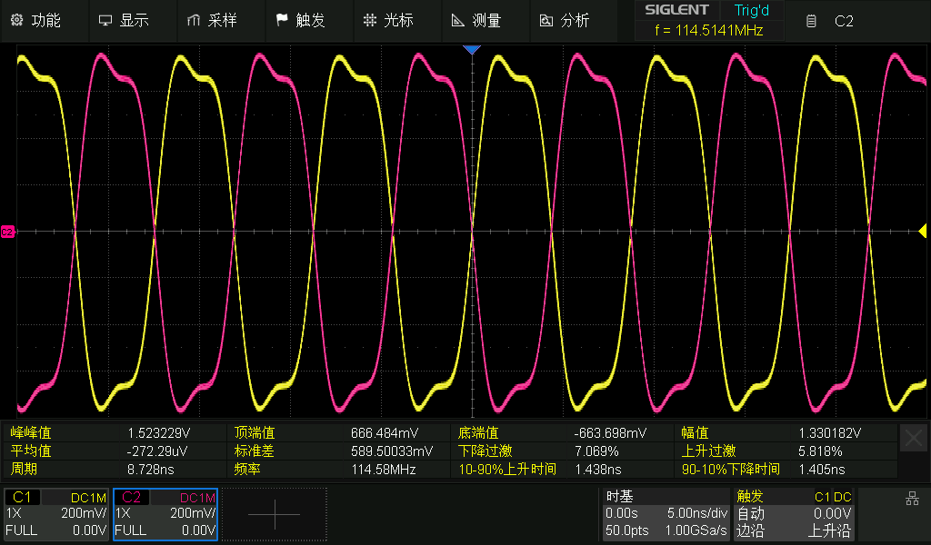
2. RF signal output: It can normally output signals of any frequency point within 20M-9800M with a theoretical resolution of 1Hz. Figure 1 shows the 114.5141MHz test by SDS804, dual-channel output; Figure 2 shows the 7.1GHz output waveform and FFT spectrum tested by Keysight.
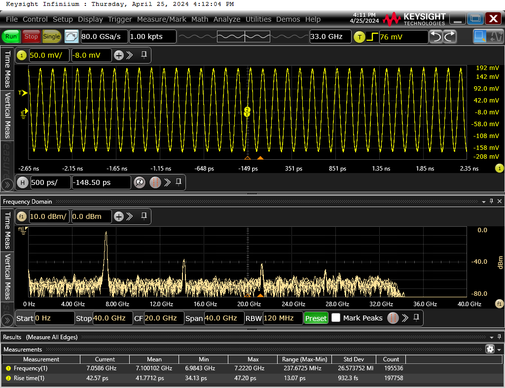
Secondly, since the maximum oscillation frequency of the VCO of this PLL is 7100MHz, a frequency multiplier on the chip is needed to multiply the VCO frequency for higher frequencies. Therefore, there is a large subharmonic (suspected to be that the chip does not suppress subharmonics). The test results are shown in the figure below. It can be seen that there is a large 4.6GHz subharmonic component at the 9.8GHz output in the FFT spectrum.

3. Reference signal output: It can normally output a 10MHz reference signal with an output impedance of 50Ω at 10MHz. Peak-to-peak voltage is 1.72V, and rise time is approximately 330ps (it can even be used for TDR), as shown in the figure below. The testing instrument is from Keysight
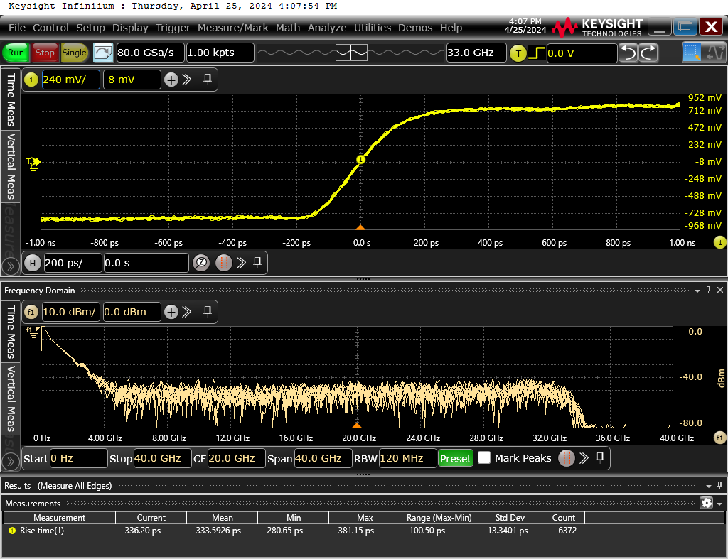
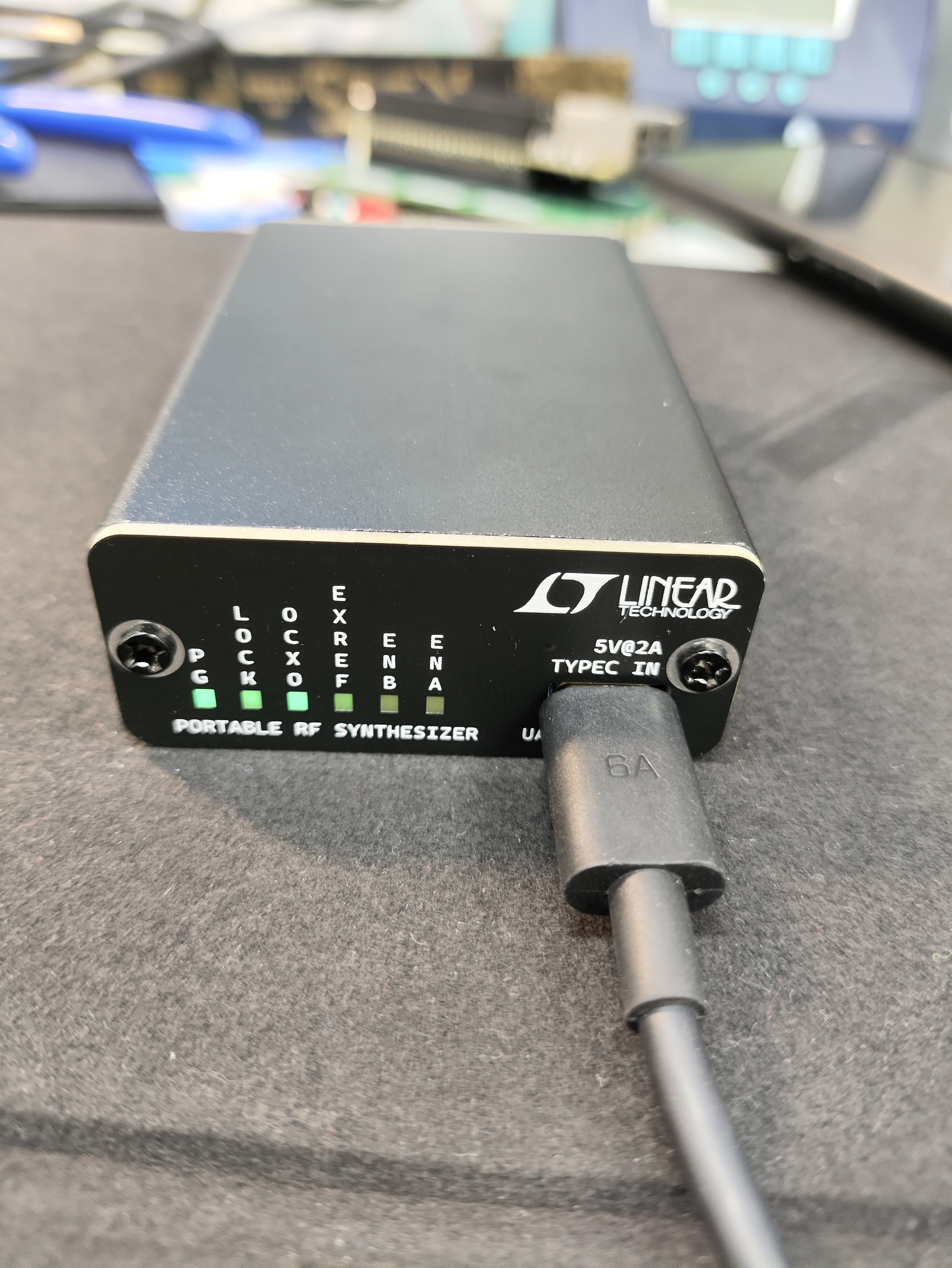
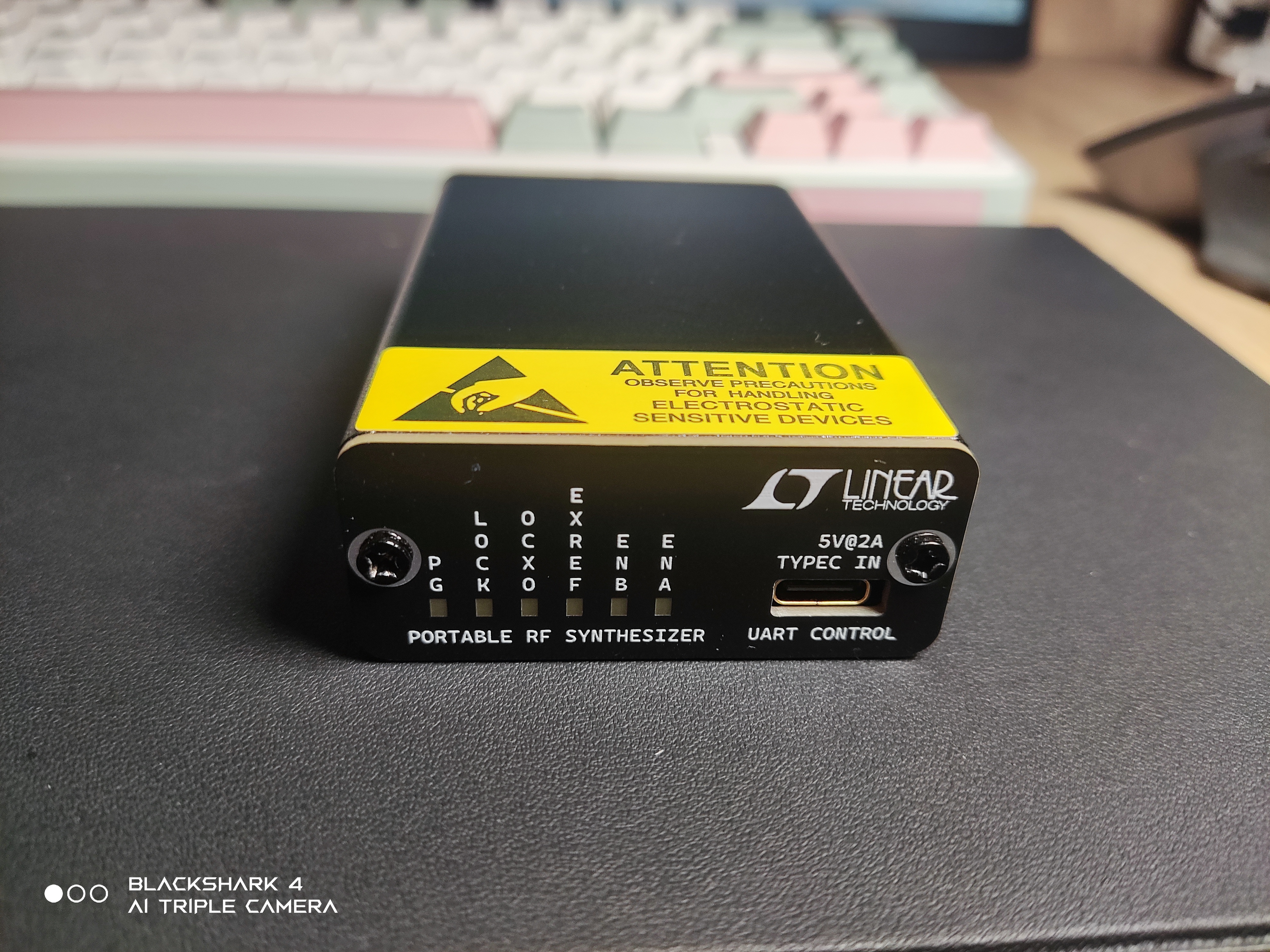
. 4. Display and Communication: Communication and LED display functions are normal. There are 6 LEDs: Power Good signal, LOCK signal, using internal reference source signal, using external reference signal, and AB channel output enable signal.
II. Software Part:
1. PLL Driver:
Control of each register of LMX2592 has been completed, and the predetermined functions can be realized.
2. UART Driver:
Serial port command control, with more than ten commands, covering basic functions. All commands
end with ' ' (0x0A), and a help menu has been written. Typing HELP
will bring up the help menu. All commands and explanations are shown in the figure below.

3. Host Computer:
Played around with QT6 and wrote a simple graphical host computer. It has all the basic functions. Currently, it supports the Win platform and can control the output frequency, reference signal switching, N-division mode, enable and disable each channel output, and output power of each channel, etc.
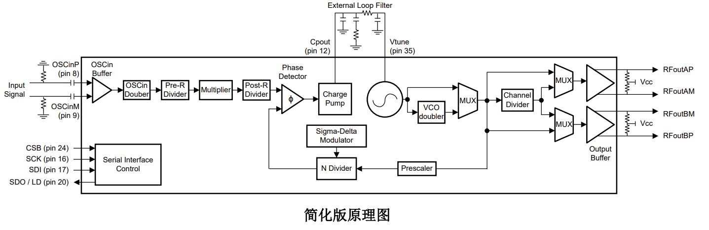
The design principle
is straightforward; essentially, it's based on a phase-locked loop (PLL) that arbitrarily multiplies the input reference signal to obtain the desired output signal. For more details, you can search on Bing. This time, the completion level is quite high; it's essentially packaged into a product, complete with a casing and host computer, plug-and-play, and very small—easily held in one hand and carried in your pocket.
The software is
based on C language, using the STM32HAL library, and developed with Keil v5.
The main control function is LMX2592_WRITE_FREQ, used to configure the PLL output frequency and basic registers. The following only demonstrates the process; detailed code can be found in the project attachments. The LMX2592 register section of the code is in the LMX2592.c/.h file:
`void LMX2592_WRITE_FREQ(double freq){
// Fvco = Fpd x PLL_N_PRE x (PLL_N + PLL_NUM / PLL_DEN)
// The VCO core covers an octave from 3.55 to 7.1 GHz.
// F_PFD=20MHz Fout = pfd * (N) / channel_div; input freq is in MHz`
// denominator = 20M (0x0131 2D00 ) the resolution = 1Hz
/****************** REF PART ********************/
/****************** OUTPUT PART ********************/
/****************** NDIV SET ********************/
/****************** STRAT WORK ********************/
}
The functions for communicating with the host computer, receiving commands, and sending status are in the UART_CTRL.c/.h file, mainly relying on the strstr function to detect commands. UART communication uses interrupt reception.
void LMX2592_FREQ_CTRL(){
temp_ret=strstr(CTRLBuffer, "FREQ=");
if(temp_ret){
RX_freq=atof(temp_ret+5);
if(debug_outen) printf("freq=%f
",RX_freq);
LMX2592_WRITE_FREQ(RX_freq);
}
...... The rest is omitted
}
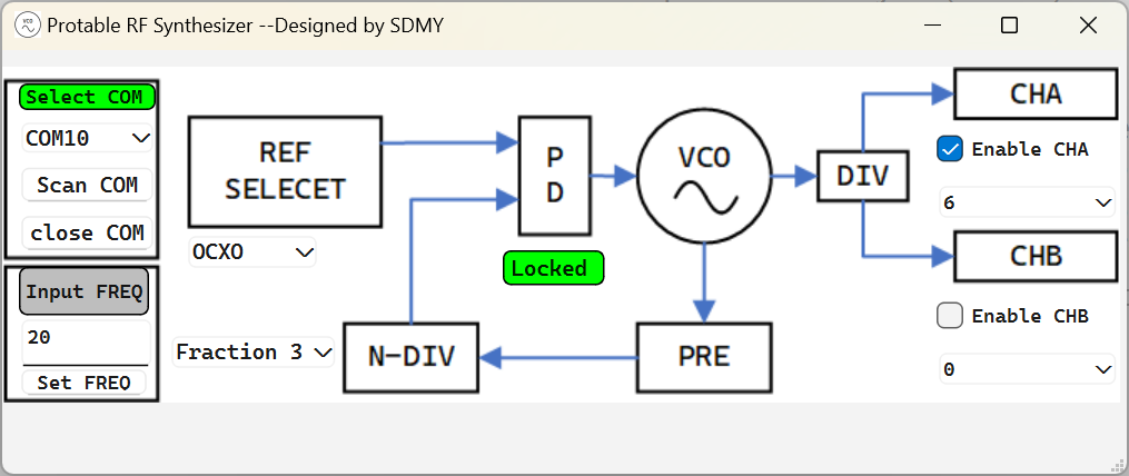
The host computer is based on QT6 CMake, which is relatively simple, but the basic functions have been implemented
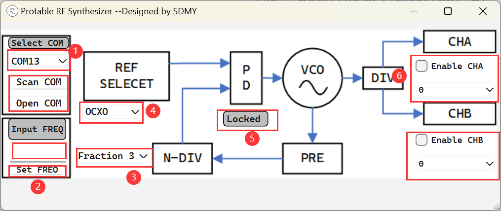
. Serial port selection area: After ensuring that the RF clock source is connected to the computer, click Scan COM to get the RF clock source serial port number, select the serial port as the RF clock source from the drop-down menu, and click Open COM to open the serial port. If the connection is successful, the Select COM indicator light above will turn green.
After connecting the serial port, enter the desired output frequency in the dialog box, the unit is MHz, the range is 20-9800, and then click Set FREQ sets the frequency. If the RF clock source is successfully locked, Locked in (5) will turn green, and the LOCK indicator on the instrument will light up.
Here, select the N-division mode. You can choose integer division or fractional division of different orders. The default is fractional division, and the order is 3.
Here, select whether the reference source is the internal OCXO or an external input. After selection, you should re-enter the frequency for VCO calibration and lock
the lock indicator. If the RF clock source is successfully locked, Locked in (5) will turn green, and the LOCK indicator on the instrument will light up.
Here, you control the output enable and output power of the AB channels. If you want the A channel to output, check Enable CHA. You can select the output power in the drop-down bar below. The B channel control is the same as A. Notes
on physical display : The small gold particles on the board are gold-plated copper particles, which serve both heat dissipation and decoration purposes. The size is 3x3x1.5 mm. When soldering, you can solder the OCXO last to prevent obstruction. The aluminum profile housing measures 54x23x80 mm and is painted black, costing approximately 9 yuan each. Due to the high power consumption of the board, a high thermal conductivity soft silicone pad should be attached to the back when inserting it into the aluminum housing to ensure tight contact between the board and the aluminum housing and conduct heat away from the housing. The thermal pad is 2.5mm thick; when the board is pushed into the aluminum housing, the housing will automatically cut off the excess thickness to achieve a tight connection. The STM32 programming port on the PCB is SWD, which can be programmed using CMSIS-DAP. The PCB is fixed to the front panel via an SMA interface and then to the housing using the screws on the front panel. During installation, the rear panel (the side with the Type-C connector) can be installed first, followed by pushing the PCB with the front panel installed into the housing and securing it. The attached Property RF Synthesizer contains a host computer program. Click the .exe file to launch it. The attached LMX2592 file is the STM32 driver and includes the STM32 cubemx configuration file. Due to upload size limitations, the complete demonstration video and instructions will be released on Bilibili. The link is here: The total cost of the pocket RF clock source is approximately 150 RMB. I wish you all success in your project.


 京公网安备 11010802033920号

 1N5256A-T


