/*****************************************************************************************************************************************************************************************/
Update
2023.3.2:
Fixed a connectivity error on the PCB. If you have prototyped your device before this update, please contact me. The modified firmware needs to be flashed for it to work properly, but RGB lighting will not be available (Sorry! T^T).
2023.3.17:
The tri-mode version is now usable. The main control chip has been replaced. It's being used in another project with the CH582M tri-mode basic PAD - JLCPCB EDA Open Source Hardware Platform (oshwhub.com)
/************************************************************************************************************************************************************************************************/
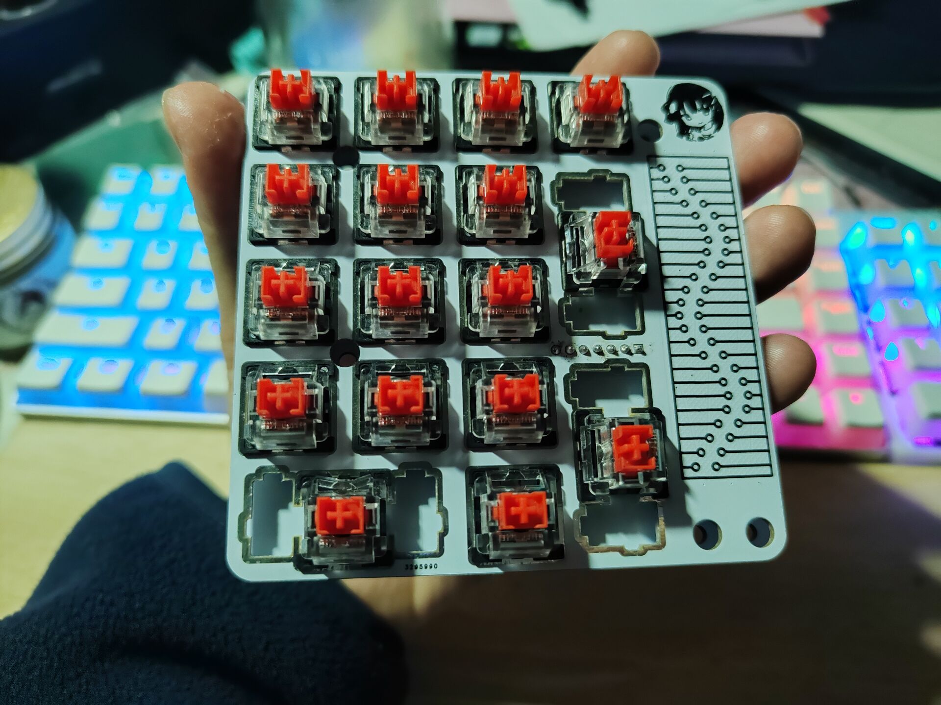
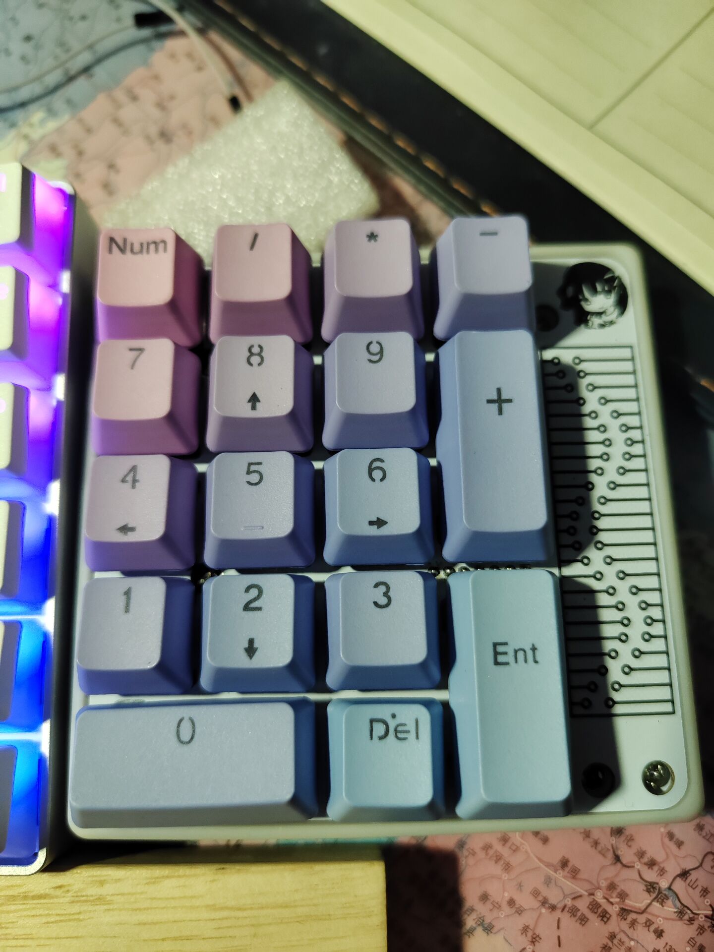
A dual-mode (or perhaps tri-mode) version of the most basic keyboard
, perfectly compatible with the basic 17+4's shell and mounting plate. It retains the valuable free shell and mounting plate,
and the frame and switch layout are taken from the most basic 17+4TPRO mechanical keyboard - JLCPCB EDA Open Source Hardware Platform (oshwhub.com).
The program is mainly modified from the CH579M Dual-Mode USB Bluetooth Keyboard with RGB - JLCPCB EDA Open Source Hardware Platform (oshwhub.com).
Function description:
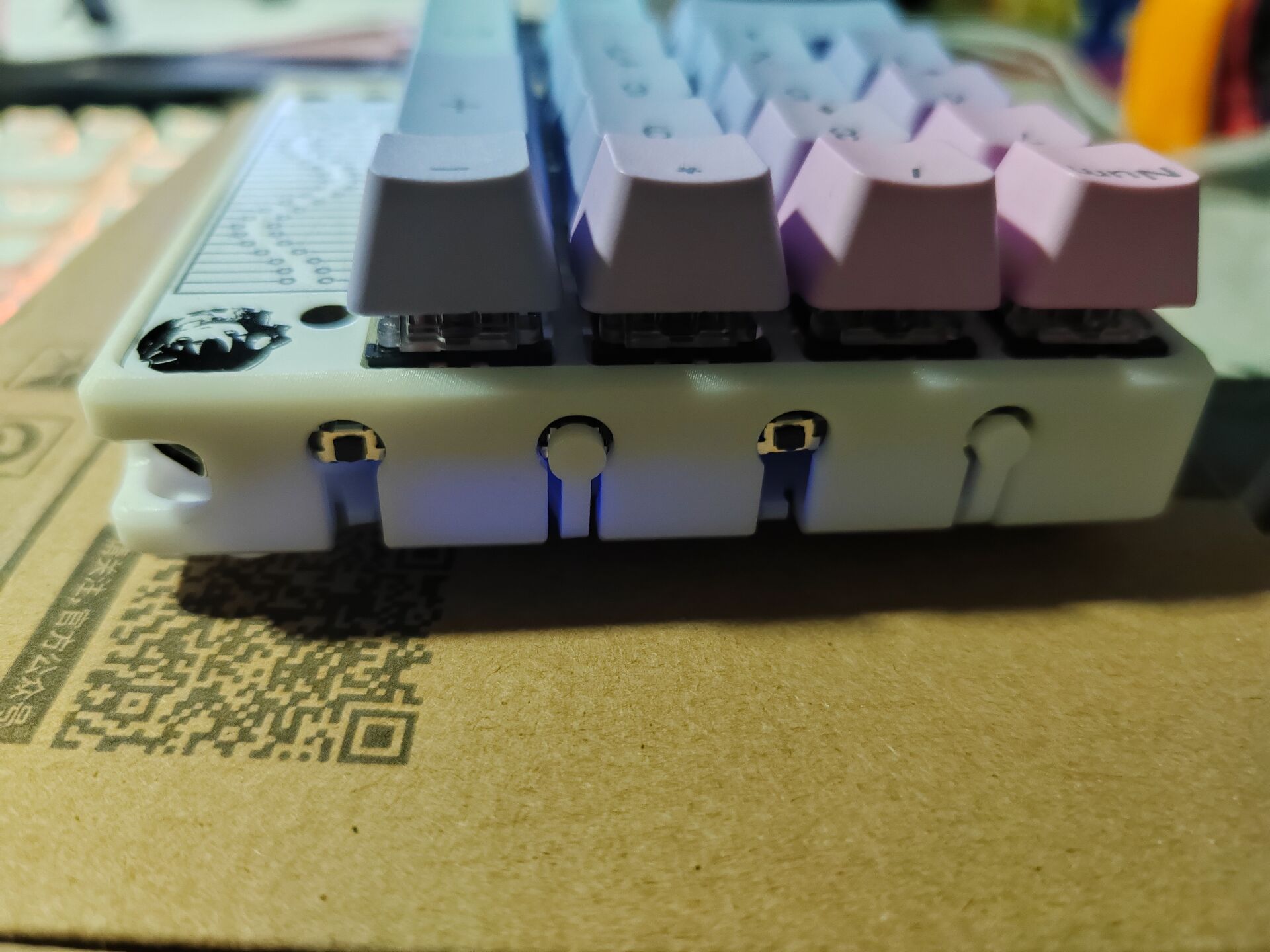
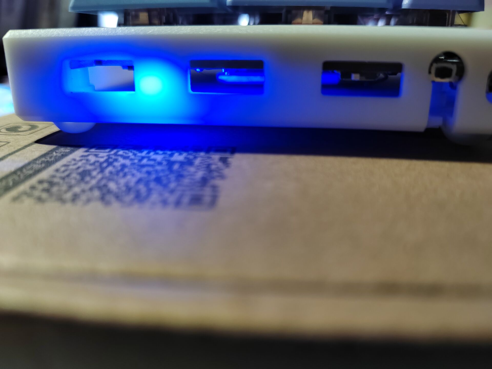
The side button is boot; press and hold boot to power on and enter download mode;
boot+/ enters USB mode (wired connection);
boot+* enters Bluetooth mode (Bluetooth name: CH579_KB_BLE)
; boot+5 If there is no operation for ten minutes in Bluetooth mode, it will enter sleep mode. The ENTER button will wake up
the indicator lights of different colors to indicate the mode, charging and main control power supply status
. RGB lighting effects (currently only one light is lit when pressed, and it can only light up when plugged in).
The four additional buttons on the top are ESC, TAB, PrintScreen, and BackSpace
to save the mode when the power was off.
Soldering precautions:
It is best to use different colors for the indicator lights (at least three mode indicator lights should be different).
It is best not to solder the pull-up resistor.
CH579M is a QFN package. It's relatively difficult to solder, so I suggest soldering it first.
During debugging, I encountered a situation where it wouldn't start. If this happens, you can solve
it by shorting the non-ground terminals of the two capacitors immediately next to the chip. The program is very messy, so I won't post it here to avoid misleading newbies.
However, you're still welcome to ask me for the program for secondary development. Upgrading to tri-mode and porting to touch is up to you! I'm just making
a promise; if you haven't started prototyping yet, you can wait a little longer. The tri-mode version of the basic 17+4 is on its way and should be available in ten days (or longer).

The space under the casing is limited; it seems it can only fit a thin battery of about 800mA, but the CH579M is low-power and can last a long time.


 京公网安备 11010802033920号

 FCE17-A15AD-K10G


