1. Hardware Selection
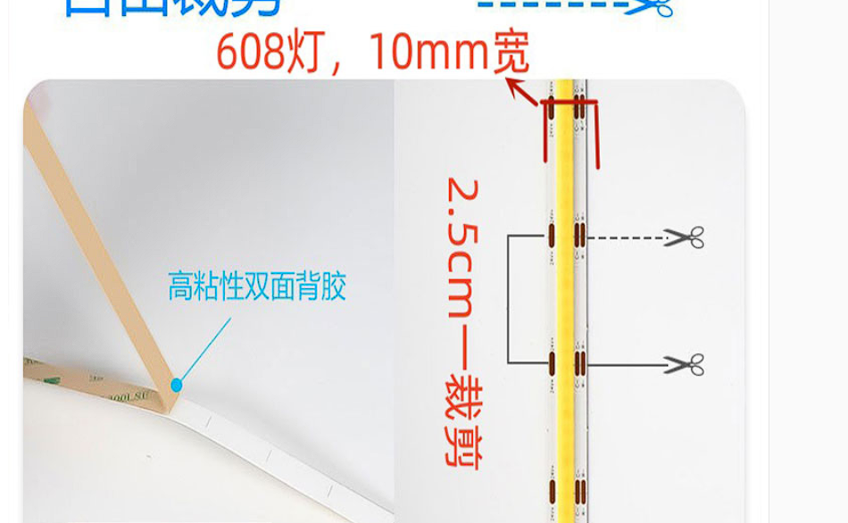
: LED Strip Lights: This design uses COB LED strip lights, which allow for separate dimming of the white and warm colors. Mixing the two colors adjusts both brightness and color temperature. If only brightness is required, a regular LED strip light can be used, allowing for simple brightness adjustment (this particular strip light, in actual testing, was somewhat underwhelming, mainly because the color temperature didn't meet my expectations).
Power: 14W/m² 608 LEDs, 10mm 3-wire DC 24V


power supply:
220V to 24V power supply is a commercially available LED power adapter.

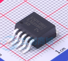
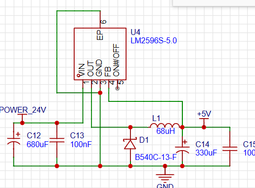
The 24V-5V power supply uses the most common DC-DC step-down regulator chip LM2596S-5V, with the following characteristics:
1. Under specific input voltage and output load conditions, the output voltage error can be guaranteed within ±4%, and the oscillation frequency error within ±15%;
2. External power failure can be achieved with only 80μA standby current;
3. It has a self-protection circuit (a two-stage frequency reduction and current limiting protection and an over-temperature complete protection circuit for power failure under abnormal conditions).
Main controller: The STM32F103CBT6 is used here, which has more memory capacity than the C8T6, allowing for the storage of more WS2812B data.
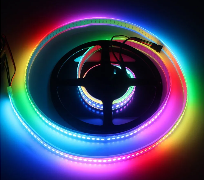
RGB LEDs: The RGB LEDs used in this design are WS2812B, with each LED representing a pixel. It supports stepless RGB color adjustment, and each LED integrates an intelligent digital interface data latch signal shaping amplification and drive circuit, as well as a high-precision internal oscillator and a programmable constant current control section, effectively ensuring high color consistency among the pixels.
2. Design Principles
Communication Data Packet Format
Frame Header
1
2
3
4
5
Frame Tail
Remarks
0xff
0xfe
Brightness 1
Brightness 2 Color Temperature
1
Color Temperature 2
0xfe
Hanging Lamp Data
0xff
0x90
Sequence Number (0-x RGB LEDs)
G
R
B
0xfe
Screen Acquisition RGB
0xff
0xca
-
-
Brightness
Rate
0xfe
Marquee
0xff
0x66
-
-
-
-
0xfe
Static Display
Hanging Lamp Dimming Principle
Adjusting the luminous intensity of white and warm LEDs mixes to achieve different color temperatures. Since both brightness and color temperature adjustments utilize changes in light intensity, the PWM width is defined as the total light brightness. The proportion of white and warm light PWM adjusts the color temperature.
LED Dimming
Active Dimming: The host computer sends the hanging lamp brightness and color temperature to the microcontroller. Based on the relationship between color temperature and brightness, the microcontroller configures the timer's PWM width according to the data content to drive the power MOSFET switch to adjust the LED strip.
/*RxState is a 1-byte buffer for the serial port */
/*--------Data frame header----------*/
if (RxState == 0){
if(RxData == 0xFF)RxState = 1;
}
/*--------Control information----------*/
else if (RxState == 1){
.........
else if(RxData==0xfe){//Control information for the hanging light mode
RxState=50;
USART1_light_RxPacket[0] = RxData;//Store it into an array
}
.........
else RxState=0;//Receive error
return;
}
//Receive hanging light information
else if(RxState==50){
USART1_light_RxPacket[pRxPacket_light+1] = RxData;//Store it into an array
pRxPacket_light ++;
if (pRxPacket_light >= 4){RxState = 3;pRxPacket_light=0;}//The light-hanging mode reception is complete, if the number of bits is sufficient
}
/*---------Judgment of the end of the data packet---------*/
else if (RxState == 3){ //If the end of the frame is received, there is no problem. The problem to be solved now is how to add reset information to the end of the frame, because screen lighting is the most likely place to make mistakes. 6.7 if (RxData == 0xFE){ RxState = 0;
}
}
Then you can set the brightness in the main program.
//Initialization
Light_Init(500,71); //2000hz, it is said online that this will not cause flicker.
//Light-hanging control
if(USART1_light_RxPacket[0]==0xfe){
//Here, the brightness and color temperature are adapted to the pulse width modulation of PWM. Because the brightness and color temperature are 2 bytes of data, and PWM is a frequency of 2000hz, so adjust it here.
Light_data.led0pwmval_warm=((float)(USART1_light_RxPacket[3]*256+USART1_light_RxPacket[4]) / 65536)*(USART1_light_RxPacket[1]*256+USART1_light_RxPacket[2])*0.0076;//=(color temperature parameter/total color temperature value)*current brightness value
Light_data.led0pwmval_while=((float)(65536-(USART1_light_RxPacket[3]*256+USART1_light_RxPacket[4])) / 65536)*(USART1_light_RxPacket[1]*256+USART1_light_RxPacket[2])*0.0076;
//Write to timer
TIM_SetCompare2(TIM2,Light_data.led0pwmval_warm);//Warm
TIM_SetCompare3(TIM2,Light_data.led0pwmval_while);//White
//Clear to 0, avoid repeatedly entering here to change the hanging light
USART1_light_RxPacket[0]=0xed;
//OLED display, for testing
Light_data.luminance=((float)(USART1_light_RxPacket[1]*256+USART1_light_RxPacket[2])/65521)*100;//Brightness index
Light_data.temperature=((float)(USART1_light_RxPacket[3]*256+USART1_light_RxPacket[4]) / 65536)*100; // Color temperature index, warm light ratio
// OLED monitoring
OLED_ShowString(1,1,"W:"); // Color temperature value - serial port reception display
OLED_ShowString(2,1,"L:"); // Brightness value - serial port reception display
OLED_ShowNum(1,3,Light_data.led0pwmval_warm,5);
OLED_ShowNum(2,3,Light_data.led0pwmval_while,5);
OLED_ShowNum(1,9,Light_data.temperature,2);OLED_ShowChar(1,11,'%'); // Display color temperature ratio
OLED_ShowNum(2,9,Light_data.luminance,2);OLED_ShowChar(2,11,'%'); // Display brightness ratio
}
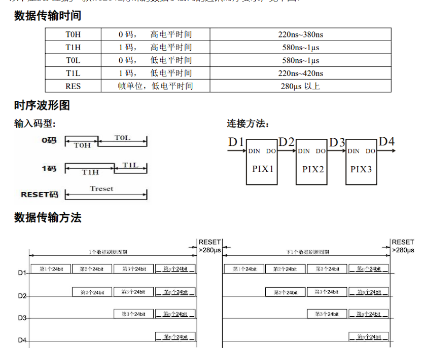
RGB screen backlight (to be improved) For information on the STM32 driver for
the WS2812B protocol, please refer to this blog post : [STM32] PWM+DMA Control of WS2812B LEDs (Library Functions) _ Huiyang's Blog - CSDN Blog. There are three methods to drive the WS2812B using STM32: 1. Manually changing the PWM pulse width to control "0" and "1" codes. This is inefficient and time-consuming, so it fails. 2. Simulating SPI timing. This is more convenient, as it transforms the WS2812B protocol into a commonly used communication protocol. 3. Using PWM+DMA data transfer. This reduces the CPU load and provides good accuracy. void WS2812_DMA_Init(){ DMA_InitTypeDef DMA_InitStructure; RCC_AHBPeriphClockCmd(RCC_AHBPeriph_DMA1,ENABLE); //Source peripheral DMA_InitStructure.DMA_MemoryBaseAddr=(uint32_t)RGB_Singel_buff;//Stores the array, that is, the pulse width value (CCR value) corresponding to 1 code DMA_InitStructure.DMA_MemoryDataSize=DMA_MemoryDataSize_HalfWord; DMA_InitStructure.DMA_MemoryInc=DMA_MemoryInc_Enable; //Destination peripheral DMA_InitStructure.DMA_PeripheralBaseAddr=(uint32_t)&TIM3->CCR4;//Transfer to here DMA_InitStructure.DMA_PeripheralDataSize=DMA_PeripheralDataSize_HalfWord; DMA_InitStructure.DMA_PeripheralInc = DMA_PeripheralInc_Disable; DMA_InitStructure.DMA_BufferSize = 2624; // Number of transfers DMA_InitStructure.DMA_DIR = DMA_DIR_PeripheralDST; // Transfer direction M->P DMA_InitStructure.DMA_M2M = DMA_M2M_Disable; // Software or hardware trigger, here it's software trigger DMA_InitStructure.DMA_Mode = DMA_Mode_Circular; // Whether to automatically reload, per transaction DMA_InitStructure.DMA_Priority = DMA_Priority_Medium; // Channel priority DMA_Init(DMA1_Channel3, &DMA_InitStructure); // DMA structure initialization DMA_Cmd(DMA1_Channel3, DISABLE); // Disable first, to prevent problems with the first pulse } //RGBData[], RGB raw data, size: quantity, number of RGB lights x 3 (R,G,B) void RGBShow(uint8_t RGBData[],uint16_t size){ TIM_Cmd(TIM3,DISABLE);
TIM_ForcedOC4Config(TIM3, TIM_ForcedAction_InActive); // Disable first to prevent problems with the first pulse
DMA_Cmd(DMA1_Channel3,DISABLE);
// Transcode
for(u16 i=0;i
for(uint8_t j=0;j
RGB_Singel_buff[j+8*i]=((RGBData[i] }
}
// Enable DMA DMA_SetCurrDataCounter(DMA1_Channel3,size*8); // Length DMA_Cmd(DMA1_Channel3,ENABLE); // Enable timer TIM_SelectOCxM(TIM3, TIM_Channel_4, TIM_OCMode_PWM1); TIM_CCxCmd(TIM3, TIM_Channel_4, TIM_CCx_Enable); TIM_Cmd(TIM3,ENABLE); // Check transmission completion flag while(DMA_GetFlagStatus(DMA1_FLAG_TC3)!=SET&&TIM_GetFlagStatus(TIM3,TIM_FLAG_CC4)==SET); //Stop DMA_ClearFlag(DMA1_FLAG_TC3); DMA_Cmd(DMA1_Channel3,DISABLE); TIM_Cmd(TIM3,DISABLE);
Asymmetrical
light source

screen light fixtures, designed to supplement the main light source, provide soft light to the eyes and screen without reflecting directly onto the screen, thus covering uneven light distribution. This reduces screen glare when using a computer at night, minimizing eye strain and the likelihood of developing or worsening nearsightedness.
My design draws inspiration from BenQ's ceiling-mounted screen light fixtures, using reflective strips to emit light and achieve an asymmetrical light source.
This part is relatively simple; the key is finding the right dimensions and refraction angles to prevent LED light from reflecting onto the screen and causing glare. My solution involves using common PVC water pipes as light tubes. I had a grinding wheel at home, so I used it to cut the pipes vertically and used a light trough to support the light strips and reflectors, carefully positioning them at the correct angle.


 京公网安备 11010802033920号

 MTB330HBVM


